
Related Manuals for Thermo King SGCO 3000


Summary of Contents for Thermo King SGCO 3000
- Page 1 SGCO 3000 (233) 2011 MAEG302598 - MAEG302830 TK 55076-4-MM (Rev. 0, 04/11) Copyright© 2011 Thermo King Corp., Minneapolis, MN, USA. Printed in USA.
- Page 2 The information in this manual is provided to assist owners, operators and service people in the proper upkeep and maintenance of Thermo King units. This Thermo King family of generator sets includes one model: SGCO. When maintenance information differs between models, this manual uses the model nomenclature (e.g.
- Page 3 Recover Refrigerant At Thermo King, we recognize the need to preserve the environment and limit the potential harm to the ozone layer that can result from allowing refrigerant to escape into the atmosphere. We strictly adhere to a policy that promotes the recovery and limits the loss of refrigerant into the atmosphere.
-
Page 5: Table Of Contents
SGCO 3000 Genset Addendum ........ - Page 6 Table of Contents Event Log Menu ..............39 Standard Display .
- Page 7 Table of Contents Flywheel Sensor ............... . . 85 Testing the Flywheel Sensor .
- Page 8 SGCO 3000 Clip-on Corner Clamp Unit Installation ........
-
Page 9: List Of Figures
Figure 3: SGCO 3000 Clip On Generator ........ - Page 10 Figure 104: SGCO 3000 Clip-on Corner Clamp Installation Procedure ......127...
-
Page 11: Sgco 3000 Genset Addendum
SGCO 3000 Genset Addendum Fuel Strainer option added to the following units: MAEG302598 - MAEG302830 Figure 1: Maersk Equipment Number Located On Vertical Frame Member Behind Alternator... - Page 12 SGCO 3000 Genset Addendum...
-
Page 13: Genset Model Features
Genset Model Features Genset Model Features TK486V Diesel Engine 460 Vac Output for 15 KW, 18.75 KVA, 3 Phase, 60 Hz, 4 Wire Generator 230 Vac Output for 15 KW, 18.75 KVA, 3 Phase, 60 Hz, 4 Wire Generator SG+ Control System Battery, Post Style Battery Charging System, Solid-state Clip-on Unit Frame... - Page 14 Genset Model Features...
-
Page 15: Safety Precautions
Safety Precautions General Practices Precautions 1. Always wear eye protection when servicing a 1. Always Wear Goggles Or Safety Glasses. battery. If electrolyte is splashed on the skin or Battery acid can permanently damage the eyes in the eyes, flush immediately under running (see First Aid under Battery Hazards). -
Page 16: Precautions
Safety Precautions Precautions The source of shock must be immediately removed by either shutting down the power or 1. Turn the generator set On/Off switch to OFF removing the victim from the source. If it is not before connecting or disconnecting a power possible to shut off the power, the wire should be plug to the generator set receptacle. -
Page 17: General Safety Precautions For Servicing Units (Or Containers) Equipped With A Microprocessor Controller
Safety Precautions General Safety Precautions for 7. If a defective controller is to be returned for repair, it should be returned in the same static Servicing Units (or Containers) protective packing materials from which the Equipped with a replacement component was removed. Microprocessor Controller 8. -
Page 18: Do Not
Safety Precautions • Do use extreme care while making adjustments on the generator set while it is running. • Do keep your hands away from moving parts. • Do disconnect the battery before starting work on a generator set. • Do use screwdrivers, pliers, diagonal pliers. -
Page 19: Serial Number Locations
Serial Number Locations The generator nameplate is attached to Generator: the generator housing. The serial number is stamped on the shell. The engine serial number is stamped on Engine: the back side of the engine block. The unit serial number nameplate is SGCO Units: attached to the unit battery box beside the engine compartment. -
Page 20: Unit Decals
Service technicians should read and follow the Serial number decals, installation decals and instructions on all warning decals. warning decals appear on all Thermo King generator sets. These decals provide information AXA0265 Unit Nameplate Location... -
Page 21: Service Guide
Service Guide This table is for Model SGCO 3000. Every Every 3000 Hours/ Trip Annual Hours Inspect/Service These Items Electrical • Perform a controller Pretrip (PTI) check. • • • Inspect battery terminals and electrolyte level. • Inspect wire harness for damaged wires or connections. - Page 22 Service Guide...
-
Page 23: Specifications
Specifications Engine Diesel Engine Model TK486V (Tier 2) Fuel Type No. 2 Diesel fuel under normal conditions No. 1 Diesel fuel is acceptable cold weather fuel Oil Capacity Crankcase and Oil Filter: 12.3 litre (13 qt) Fill to full mark on dipstick Oil Type: Multi-grade Petroleum Oil (Standard) Synthetic Oil (Optional) after first 500 hours... -
Page 24: Electrical Control System
Specifications Electrical Control System Controls SG+ microprocessor controller Voltage 12.5 Vdc (nominal) Battery 12 volts, group C31, 925/950 Cold Cranking Amps at -18 C (0 F) Fuse SI1 30 Amp Fuse SI2 30 Amp Fuse SI3 10 Amp Electrical Components NOTE: Disconnect components from unit circuit to check resistance. -
Page 25: Physical Specifications
Specifications Physical Specifications Weight (net): SGCO 3000 818 Kg (1804 lbs) including oil, coolant, battery and 473 liter (125 gal.) fuel tank (excluding fuel) Unit Dimensions: AXA0271... -
Page 26: Metric Hardware Torque Charts
Specifications Metric Hardware Torque Charts Bolt Size Bolt Type and Class* N.m (Ft.-lb.) N.m (Ft.-lb.) N.m (Ft.-lb.) N.m (Ft.-lb.) HH – CL 5.8 6-9 (4-7) 12-16 (9-12) 27-34 (20-25) 48-61 (35-40) HH – CL 8.8 10-13 (7-10) 20-27 (15-20) 41-47 (30-35) 75-88 (55-65) HH –... -
Page 27: Unit Description, Features & Options
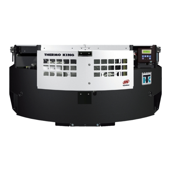
Enclosed within the unit frame are the engine, dual voltage alternator, generator battery compartment, battery charging regulator and control panel. AXA0274 Figure 3: SGCO 3000 Clip On Generator CAUTION: DO NOT attempt to operate or maintain the generator until you have completely familiarized yourself with the equipment. -
Page 28: Emi 3000 Package
However, please note that units equipped Unit Instruments with the EMI 3000 package still require regular INDICATOR LEDs. inspection in accordance with Thermo King pretrip inspection and maintenance a. POWER LED: A green Power LED lights recommendations (see the Service Guide chapter up while the Unit On/Off Switch is in the in this manual). -
Page 29: Unit Protection Devices
Unit Description, Features & Options Unit Protection Devices EcoPower Option EcoPower is an option designed to save fuel. A WARNING: the unit may start at any time speed solenoid is mounted on the engine and without warning when the unit On/Off controlled by the controller. -
Page 30: Figure 6: Sgco 3000 - Unit Front View
Fuel Tank Fill Neck and Cap (each side) Access Doors Coolant Expansion Tank Location Upper Unit Mounting Clamps (Corner Clamp Equipped Units Only) 460 or 230 Vac Power Receptacle Header Pin Mounting Flange (Header Pin Equipped Location Units Only) Figure 6: SGCO 3000 — Unit Front View... -
Page 31: Figure 7: Powerpack (All Models) - Unit Front View
Unit Description, Features & Options Air Inlet Adapter Oil Fill and Dipstick Alternator Oil Level Sensor Starter Oil Drain Timing Mark Location Engine Speed Adjustment Screw Flywheel Sensor Water Pump Pulley Oil Filter Water Temperature Sensor Low Oil Pressure Switch Figure 7: Powerpack (All Models) —... - Page 32 Unit Description, Features & Options...
-
Page 33: Controller Description
Controller Description SG+ Controller Description The SG+ controller is a two-piece, self contained microprocessor for diesel generator sets. The SG+ display is mounted on the control box cover. The SG+ microprocessor is mounted inside the control box (see Figure 9 on page 34). Two external relays, the Start Relay and the Preheat Relay, are also mounted inside the control box near the microprocessor. -
Page 34: Figure 9: Sg+ Microprocessor
Controller Description J6 Connector – To AC Circuits Fuse SI1 – 30 Amp Protects 8D and 8DP Circuits Fuse SI2 – 30 Amp Protects Battery Charger Output Circuit 2A Circuit Connection CH Circuit Connection GND Circuit Connection Serial Port – For Flash Loading Software J2 Connector –... -
Page 35: Controller Overview
Controller Description Controller Overview A vacuum lucent display on the front Display: panel shows operating information including output voltage, current test state during a Pretrip test and the controller menu. Normally it shows the Output Voltage (this is called the Standard Display). -
Page 36: Miscellaneous Features
Controller Description Miscellaneous Features • Microprocessor Outputs: • Start Relay • Internal self-checking/diagnostic capability • Preheat Relay • Pretrip test capability (see “PTI” on page 59) • Fuel Pull Relay • Hourmeter: The controller has a built-in run • Fuel Hold Relay hourmeter that can be accessed through the Timers/Counters Submenu under the Misc. -
Page 37: Navigating The Controller Menus
Navigating the Controller Menus Press the key each time Controller Display Menus Down Key: you want to scroll down to view another The SG+ controller contains extensive display item in a menu (or submenu), or decrease menus that can be navigated via the keypad. The the value of a setting. -
Page 38: Menu Overview
Navigating the Controller Menus Menu Overview Press the keys to scroll through the Main Menu or a Submenu. Press the key to NTER enter a Submenu or Event. Press the key to SCAPE return to the parent menu. Main Menu Submenu Event ANALOG INPUTS... -
Page 39: Data Menu
Navigating the Controller Menus Data Menu • System Setup, which is used to check the engine speed, energize and de-energize the The Data Menu contains the following submenus. Speed Solenoid, set the unit fuel tank size, set See “Data Menu” on page 46 for more the date and time, and set an ID number to information. -
Page 40: Standard Display
Navigating the Controller Menus Standard Display Pause Mode Displays The Standard Display shows the output voltage. It WARNING: The AC alternator output or appears approximately one minute after the last engine may start at any time without key is pressed while the unit is running. The notice when the unit is in a PAUSE mode. -
Page 41: Operating Instructions
Operating Instructions Visually inspect the unit for leaks, Pretrip Inspection Structural: loose or broken parts and other damage. The The pretrip inspection is an important part of the radiator coil should be clean and free of debris. preventive maintenance program. It’s designed to Clean if necessary. -
Page 42: Starting The Unit
Operating Instructions Starting the Unit g. MAIN MENU DATA Generator sets are designed to provide power for a AIR HEATER ON refrigeration unit. Before starting the generator This display appears only if the controller set, make sure the refrigeration unit power cord is determines that the engine coolant connected to the generator set electric power temperature is low enough to require that... -
Page 43: After Start Inspection
Operating Instructions l. MAIN MENU a. Press the key or the key to NTER SCAPE DATA enter the Main Menu, if necessary. SPEED MEAS b. Press the key to scroll up or This display appears only on units down through the Main Menu to the equipped with the EcoPower option while Commands Menu. - Page 44 Operating Instructions NOTE: If a component fails its test, the PTI will stop at that point and display “FAILED - REBOOT”. Correct the problem and repeat the PTI by pressing the Key. NTER 4. When the PTI is complete, the test ends automatically and the controller display shows “PTI PASSED (or FAILED) - REBOOT”.
-
Page 45: Main Menu
Operating Instructions Main Menu To enter the Main Menu complete the following steps: The Main Menu contains the following menus: 1. Place the On/Off switch in the “ON” position. • Data Menu 2. Press the key or the key to enter NTER SCAPE •... -
Page 46: Data Menu
Operating Instructions Data Menu 2. Press the key or the key to enter NTER SCAPE the Main Menu, if necessary. NOTE: The Data Menu only displays 3. The Data Menu is typically the first menu information, items can NOT be changed. displayed in the Main Menu. -
Page 47: Analog Inputs
Operating Instructions Analog Inputs To "ANALOG INPUTS" From "ANALOG INPUTS" The Analog Inputs display the following unit prompt of "DATA" menu. prompt of "DATA" menu. operating information: • Voltage Meas. (AC Output Voltage) VOLTAGE MEAS. 460 V • Field Current (Current on F1) FIELD CURRENT 1.1 A WATER TEMP. -
Page 48: Digital Inputs
Operating Instructions Digital Inputs To "DIGITAL INPUT" prompt From "DIGITAL INPUT" prompt The Digital Inputs display the status of the of "DATA" menu. of "DATA" menu. following inputs: • Air Filter Switch AIR FILTER SWITCH OFF COOLANT LEVEL LOW OFF •... -
Page 49: Digital Outputs
Operating Instructions Digital Outputs To "DIGITAL OUTPUT" From "DIGITAL OUTPUT" The Digital Outputs display the status of the prompt of "DATA" menu. prompt of "DATA" menu. following outputs: • Bat. Charger BAT. CHARGER START RELAY • Start Relay PREHEAT RELAY •... -
Page 50: Internal States
Operating Instructions Internal States To "INTERNAL STATES" From "INTERNAL STATES" prompt of "DATA" menu. prompt of "DATA" menu. The Internal States displays which of the following states the unit is in as it prepares to start, and after it starts or if it shuts down: •... -
Page 51: Alarm List Menu
Operating Instructions Alarm List Menu 3. The Alarm List Menu will appear on the display. It shows the most recent alarm and the The Alarm List Menu displays alarms. Alarms are following information: recorded in the controller memory to simplify unit •... - Page 52 Operating Instructions Alarm List Alarm Code and Text Alarm Type–Cause Diagnostics 101. Delayed Restart Alarm–Engine is 1. Check for cause of engine WATER TEMPERATURE running and water temperature is above overheating: HIGH 107 C (225 F) for 25 seconds. • Check engine coolant level. •...
- Page 53 Operating Instructions Alarm List (Continued) Alarm Code and Text Alarm Type–Cause Diagnostics 109. If low oil level and low oil pressure is 1. Check oil level. LOW OIL LEVEL present at the same time. 2. Check Oil Level Switch. 3. Check circuits to Oil Level Switch. 4.
-
Page 54: Message List Menu
Operating Instructions Message List Menu 8. Press the key to scroll down to the next message, if necessary. The Message List Menu displays messages. 9. Write down the message code and the Messages are recorded in the controller memory message text. to simplify unit diagnostic procedures. - Page 55 Operating Instructions Message List Message Code and Text Cause Diagnostics 101. Battery Voltage is below 9 volts. 1. Check battery BAT. VOLTAGE LOW 2. Check battery cables. 102. Digital inputs have been changing once This condition indicates noise on the line, DIGITAL INPUT FAILURE a second for the last 10 seconds.
- Page 56 Operating Instructions Message List (Continued) Message Code and Text Cause Diagnostics 115. No feedback when relay is energized, or 1. Check RL6 (Preheat) relay. RL6 (AIRHEAT) feedback when relay is not energized. 2. Check PHR, PPHR, and FPHR FEEDBACK FAILURE circuits.
- Page 57 Operating Instructions Message List (Continued) Message Code and Text Cause Diagnostics 125. RL3 No feedback when relay is energized, or 1. Check RL3 (Speed [Throttle] (SPEED SOLENOID) feedback when relay is not energized. Solenoid) relay. FEEDBACK FAILURE 2. Check 7D circuit. 126.
-
Page 58: Commands Menu
Operating Instructions Commands Menu 3. Press the key to scroll up or down through the Main Menu to the Commands The Commands Menu contains the following Menu. submenus that are used to test the operation or the 4. Press the key to enter the Commands unit and controller: NTER... -
Page 59: Pti
Operating Instructions m. The start relay is tested. The PTI (Pretrip Inspection Test) initiates a test of n. The output voltage is tested. the unit’s electrical, engine, and alternator system o. The engine starts. components. To perform a PTI complete the following steps: p. -
Page 60: Manual Function Test
Operating Instructions Manual Function Test 4. Press the key to enter the Commands NTER Menu. The Manual Function Test submenu contains the following component tests: 5. The PTI submenu will be displayed. • Display Test 6. Press the key to scroll up or down through the Commands Menu to the Manual •... -
Page 61: Figure 26: Manual Function Test Submenu
Operating Instructions To "MANUAL FUNCTION TEST" From "MANUAL FUNCTION TEST" prompt of "COMMANDS" menu. prompt of "COMMANDS" menu. DISPLAY TEST PERFORM TEST PREHEAT RELAY TEST FUEL HOLD RELAY TEST FUEL PULL RELAY TEST PERFORM DISPLAY TEST TEST PREHEAT RELAY TEST FUEL HOLD RELAY TEST FUEL PULL RELAY TEST PERFORM... -
Page 62: System Setup
Operating Instructions System Setup 4. Press the key to enter the Commands NTER Menu. The System Setup submenu contains the following: 5. The PTI submenu will be displayed. • Current RPM, which is used to check the 6. Press the key to scroll up or down engine speed. -
Page 63: Figure 27: System Setup Submenu
Operating Instructions To "SYSTEM SETUP" prompt From "SYSTEM SETUP" prompt of "COMMANDS" menu. of "COMMANDS" menu. CURRENT RPM 1890 SPEED SOLENOID TANK SIZE FUEL SENSOR CURRENT RPM 1890 ENTER CHANGE FUNCTION SPEED SPEED SOLENOID TANK SIZE FUEL SENSOR ENTER CHANGE CURRENT RPM 1890 FUNCTION... -
Page 64: Date/Time
Operating Instructions Date/Time From "DATE/TIME" prompt of Save changes and return to The Date/Time submenu is used to set the clock in "MISC. FUNCTIONS" menu. "DATE/TIME" prompt of the controller. To enter the Date/Time submenu "MISC. FUNCTIONS" menu and set the clock complete the following steps: YEAR: 2006 1. -
Page 65: Misc. Functions Menu
Operating Instructions Misc. Functions Menu 3. Press the key to scroll up or down through the Main Menu to the Misc. Functions The Misc. Functions Menu contains the following Menu. submenus: 4. Press the key to enter the Misc. NTER •... -
Page 66: C/F Mode
Operating Instructions C/F Mode From "C/F MODE" prompt of "MISC. FUNCTIONS" menu. The C/F Mode submenu is used to select whether Save changes and return to "C/F MODE" prompt of Celsius or Fahrenheit units are used to display "MISC. FUNCTIONS" menu temperature readings. -
Page 67: Sw/Hw Version
Operating Instructions SW/HW Version To "PROGRAM VERSION" From "PROGRAM VERSION" prompt of "MISC. prompt of "MISC. The SW/HW Version submenu displays the FUNCTIONS" menu FUNCTIONS" menu following information about the controller: • SW (Software Version) • HARDWARE REV. (Hardware Revision) SW xxxxxx xx HARDWARE REV. -
Page 68: Timers/Counters
Operating Instructions Timers/Counters 5. Press the key to scroll up or down through the Misc. Functions Menu to the The Timers/Counters submenu displays the Timers/Counters submenu. following information about the hourmeters and restart counters: 6. Press the key to enter the NTER Timers/Counters submenu. -
Page 69: Configuration Menu
Operating Instructions Configuration Menu • Output Voltage – The default setting is 460. The other selection is 230, which is used is the The Configuration Menu is used to configure the alternator is configured for an output voltage following controller functions (also see the of 230 Vac. -
Page 70: Figure 33: Configuration Menu
Operating Instructions To "CONFIGURATION" From "CONFIGURATION" prompt of "MAIN" menu. prompt of "MAIN" menu. LOP RESTART LOP RESTART Toggle between ON/OFF DEL COLDSTART DEL COLDSTART PASS- HM1 THRESHOLD 00000 HM1 THRESHOLD 00000 Toggle between ON/OFF WORD HM2 THRESHOLD 00000 HM2 THRESHOLD 00000 LOP RESTART LOP RESTART... -
Page 71: Figure 34: Configuration Menu
Operating Instructions To/From Page 1 of Configuration Menu FACTORY RESET FACTORY RESET Toggle between ON/OFF APU CONNECTED APU CONNECTED PASS- OUTPUT VOLTAGE OUTPUT VOLTAGE Toggle between ON/OFF WORD FUEL SENSOR FUEL SENSOR Scrolls cursor right APU CONNECTED APU CONNECTED OUTPUT VOLTAGE OUTPUT VOLTAGE Roll the active figure up PASS-... -
Page 72: Setting Hour Meter Thresholds And Resetting Hour Meters
Operating Instructions Setting Hour Meter Thresholds and 10. Press the key to move the cursor to NTER Resetting Hour Meters select the value you want to change. The Hour Meter Threshold feature sets the NOTE: For example, to change the setting controller to alert the user that the unit has for the HM1 Threshold to 400 hours, press operated for a defined number of hours. -
Page 73: Event Log Menu
Operating Instructions Event Log Menu 3. Press the key to scroll up or down through the Main Menu to the Event Log The Event Log Menu contains the following Menu. submenus that show events that are recorded in 4. Press the key to enter the Event Log the controller memory: NTER... -
Page 74: Event Log
Operating Instructions Event Log To "EVENT LOG" prompt From "EVENT LOG" prompt The Event Log is a list of events that are recorded of "EVENT LOG" menu of "EVENT LOG" menu in the controller memory. Examples of recorded events are a system power up, alarms, and 20YY.MM.DD-HH.MM messages. -
Page 75: Figure 37: Fuel Events Submenu
Operating Instructions 5. The Event Log submenu will be displayed. To "FUEL EVENTS" prompt From "FUEL EVENTS" prompt of "EVENT LOG" menu of "EVENT LOG" menu 6. Press the key to scroll up or down to the Fuel Events submenu. 7. -
Page 76: Logview And Viewing Sg+ Logs
Operating Instructions LogView and Viewing SG+ Logs With the release of SG+ software 08042300, some changes were made to the description so the log With the release of LogView software version may have different wording based on the software 5.9.2.0 (or later), you can now view SG+ Event that was in the controller at the time of the logs. -
Page 77: Figure 38: Example Of Sg+ Log
Operating Instructions Event Log Report Container ID: APZJ007063 LogView: 5.9.2.0 SGPlus2LogView.dll: Rev. : 1.1.1.9 Thermo King SG+ Event Log Time for transfer : 080826 16:13 Retriever ID : LogMan II PC v. 2.0.2 SG+ software version : 080423 revision 00... - Page 78 Operating Instructions...
-
Page 79: Electrical Maintenance
Electrical Maintenance Battery will not stay energized. The RL2 LED on the PC board will light up when the fuel hold relay is CAUTION: Place the Unit On/Off switch energized. in the “OFF” position, Before connecting or disconnecting the unit battery, Speed (Throttle) Solenoid Relay Inspect and clean the battery terminals, check the The speed solenoid relay (RL3) is used on units... -
Page 80: Start Relay
Electrical Maintenance Start Relay Unit Wiring The start relay (RL5) is mounted on the inside of Inspect the unit wiring and wire harnesses during the control box. It is energized by the controller scheduled maintenance inspections for loose, after proper preheat time has occurred. When this chaffed or broken wires. -
Page 81: Air Heater
Electrical Maintenance Air Heater 2. Continuity tester should indicate a complete circuit between the terminal and ground. The air heater heats the intake air to help the 3. Start the engine. Tester should show an open engine start in cold weather. The air heater is circuit between each terminal and ground. -
Page 82: Oil Level Sensor
Electrical Maintenance Oil Level Sensor 5. The switch should be open and there should be no continuity between the switch wires. If the engine oil level drops below the actuation (When the oil level is between the low mark level, the low oil level sensor (OLS) switch will and the full mark on the dipstick). -
Page 83: Coolant Temperature Sensor
Electrical Maintenance Coolant Temperature Sensor NOTE: Polarity must be considered when connecting temperature sensors. If a sensor is The coolant temperature sensor is connected to connected backwards, the display will show a the engine coolant system near the water pump. It reading below -40 C (-40 F) or above 130 C (266 uses coolant temperature to present a variable F) and record Alarm Code 101. -
Page 84: Coolant Level Detector Sensor
Electrical Maintenance Coolant Level Detector Sensor Sensor Test 1. Ground the sensor to chassis ground with a The coolant level detector sensor is a stainless jumper wire. steel probe immersed in the coolant. It is located on the side of the radiator. It does not fail or wear 2. -
Page 85: Flywheel Sensor
Electrical Maintenance Flywheel Sensor 4. Start and operate the unit. 5. Check the ac voltage output across the sensor The flywheel sensor is in the engine bell housing terminals. Use a meter with a high ohms per adjacent to, but not touching, the flywheel volt internal resistance. - Page 86 Electrical Maintenance...
-
Page 87: Engine Maintenance
The oil filter should be changed along with the NOTE: Units equipped with the EMI 3000 engine oil. Use a genuine Thermo King extended package do require regular inspection in maintenance oil filter. accordance with Thermo King's maintenance 1. -
Page 88: Low Oil Pressure
Engine Maintenance Low Oil Pressure pressure regulating valve, or worn bearings. Low oil pressure is not normally caused by a faulty oil Oil pressure is affected by oil temperature, oil pump. Use the following “Low Oil Pressure Flow viscosity, and engine speed. Low oil pressure can Chart”... -
Page 89: Crankcase Breather
Engine Maintenance Crankcase Breather Normal crankcase pressures with a new air cleaner are 2 to 12 in. (50 to 300 mm) H O of Gases formed in the crankcase are directed to the vacuum. The vacuum will increase as the air intake manifold. -
Page 90: Cyclonic Dry Air Cleaner
Engine Maintenance Cyclonic Dry Air Cleaner The cyclonic dry air cleaner is a dry element air cleaner used on units manufactured after 11/15/02. It filters all of the air entering the engine. Replace the dry air cleaner element when the air restriction indicator reads 25 in. of vacuum, or at 2 years, whichever comes first. -
Page 91: Engine Cooling System
The following are the Extended Life Coolants 1. Prevents freezing down to -34 C (-30 F). currently approved by Thermo King for use in 2. Retards rust and mineral scale that can cause ELC units for five years or 12,000 hours: the engine to overheat. -
Page 92: Figure 54: Sgco Engine Cooling System
Engine Maintenance NOTE: The use of 50/50 percent pre-mixed Extended Life Coolant (ELC) is recommended to assure that de-ionized water is being used. If 100 percent full strength concentrate is used, de-ionized or distilled water is recommended over tap water to insure the integrity of the cooling system is maintained. -
Page 93: Antifreeze Maintenance Procedure
ELC coolants are available in 100 percent full extreme temperatures. strength concentrate or (pre-mixed) 50/50 percent mixture. Thermo King recommends the use of Changing the Antifreeze 50/50 percent pre-mixed ELC antifreeze to assure that de-ionized water is used. 100 percent 1. -
Page 94: Bleeding Air From The Cooling System
50/50 mixture because the exact cooling system capacity may not be known. NOTE: Thermo King recommends the use of 50/50 percent pre-mixed ELC antifreeze to assure that de-ionized water is used. 100 percent concentrate extended life coolant... -
Page 95: Engine Thermostat
Engine Maintenance Engine Thermostat The hand fuel pump is used to manually draw fuel from the tank up to the transfer pump if the unit TK486V engines use a 71 C (160 F) thermostat. should run out of fuel. The transfer pump draws fuel from the fuel tank through a fuel inlet strainer at the inlet to the transfer pump. -
Page 96: Figure 57: Fuel System
Engine Maintenance • Complete the work in the shortest possible • Prime pump (hand) replacement or repair* time. • Transfer pump replacement or repair* Any major injection pump or nozzle repairs • Injection line replacement* should be done by a quality diesel injection service shop. -
Page 97: Fuel Return Line Replacement
Engine Maintenance Fuel Return Line Replacement 2. Discard the old clamps, end cap, and fuel return lines. The fuel return lines (hoses) and end cap on the fuel injection nozzles should be changed every 3. Install the end cap and clamp. Note that the 10,000 engine operating hours. -
Page 98: Water In The Fuel System
Engine Maintenance 2. Unscrew the priming pump handle and 2. Fill the new filter with clean fuel through one manually prime the fuel system until air of the small openings in the top of the filter bubbles are no longer visible in the fuel body. -
Page 99: Engine Speed Adjustment
Engine Maintenance 5. Tighten the jam nut, when the speed is correct. Fuel Solenoid Speed Adjustment Screw Figure 62: Engine Speed Adjustment Head for Standard Unit Gasket Adjustment Procedure for Units Screen with EcoPower Option Bowl Figure 61: Fuel Strainer Components Make the engine speed adjustments with the engine fully warmed up. -
Page 100: Integral Fuel Solenoid
Engine Maintenance Integral Fuel Solenoid 7. Check the engine speed. The engine speed should be 1890 ± 10 RPM with No Load and The fuel solenoid contains 2 coils: the pull-in coil, the Speed Solenoid On. and the hold-in coil. The pull-in coil draws a. - Page 101 Engine Maintenance If you suspect that the engine does not operate battery terminal. The fuel solenoid should because the fuel solenoid is not operating make a definite click when the pull-in coil is correctly, use the following procedure: energized. It should click again when the pull-in coil is de-energized.
-
Page 102: Fuel Solenoid Replacement
Engine Maintenance 11. Reconnect the main wire harness connector to the fuel solenoid connector. 12. Connect wire 8S to the starter solenoid. Fuel Solenoid Replacement 1. Disconnect wire 8S from the starter solenoid. 2. Disconnect the fuel solenoid wire connector. 3. -
Page 103: Injection Pump Service And Timing
Engine Maintenance Injection Pump Service and Timing Injection Pump Removal The injection pump drive gear will not fit through the gear housing when removing the pump. The gear must be separated from the pump using tool P/N 204-1011. When this tool is used, it is not necessary to remove the water pump belt, fuel pump, crankshaft pulley, crankshaft seal or front plate. -
Page 104: Injection Pump Installation
Engine Maintenance of the injection pump shaft. Then rotate the NOTE: If a different injection pump is being screw to force the injection pump shaft from installed, see “Injection Pump Timing” on the gear. page 105 to set the timing. 7. -
Page 105: Injection Pump Timing
Engine Maintenance Injection Pump Timing Use this timing procedure when installing a new injection pump. It is not necessary to use this timing procedure when removing and reinstalling the original injection pump. In that case, align the index marks on the injection pump and the gear case as they were before removing the injection Index Mark on Injection Pump pump. -
Page 106: Figure 74: Removing Injection Pump Gear
Do Not Loosen or Remove These Four Bolts NOTE: If you cannot read the injection angle Remove Nut and Lock Washer mark, contact the Thermo King Service Department with the injection pump serial Figure 74: Removing Injection Pump Gear number or the engine serial number and they 4. -
Page 107: Figure 78: Examples Of Injection Pump Index Mark Alignment With Injection Angle Sticker
Engine Maintenance 5. Record the injection angle marked on the side of the new injection pump. 6. Calculate the injection angle difference by subtracting the injection angle of the old injection pump from the injection angle of the new injection pump. Examples Injection Angle of New Injection Pump (Degrees) -
Page 108: Trochoid Feed Pump
Engine Maintenance Trochoid Feed Pump Trochoid Feed Pump Replacement The TK486V engine has a trochoid feed pump on Use the following procedure to replace the the fuel injection pump. The trochoid feed pump trochoid feed pump. supplies fuel to the injection pump at a pressure of 1. -
Page 109: Cold Start Device
Engine Maintenance 3. Place new O-rings on the new trochoid feed pump and make sure it is clean. Plunger (Extended) Figure 84: Cold Start Device Checking Cold Start Device Operation Use the following procedure to check the O-Rings operation of the cold start device. The engine Figure 83: Trochoid Feed Pump coolant temperature must be below 0 C (32 F) to 4. -
Page 110: Figure 85: Remove Engine Coolant Fitting
Engine Maintenance Cold Start Device Replacement 4. Make sure the piston inside the injection pump fitting is clean. 1. Drain the engine coolant. 2. Remove the banjo bolt that fastens the engine coolant fitting to the cold start device. Use a backup wrench on the cold start device if necessary. -
Page 111: Adjusting Engine Valve Clearance
Engine Maintenance Adjusting Engine Valve b. Check the rocker arms on the number one cylinder. Clearance c. If the rocker arms are loose, the engine is Valve clearance should be checked as required. It at top dead center of the compression is very important that valves be adjusted to the stroke for the number one cylinder. -
Page 112: Figure 90: Valve Adjustment And Cylinder Configurations
Engine Maintenance 8. Rotate the engine one full turn (360 degrees) 9. Check and adjust both valves for the number to place the engine at top dead center of the four cylinder. Also check the valve clearance compression stroke for the number four for the intake valve for the number three cylinder. -
Page 113: Belt Tension Adjustment And Belt Replacement
Engine Maintenance Belt Tension Adjustment and Belt Replacement NOTE: Belt tension specifications are measured using Thermo King belt gauge tool, P/N 2 3 4 5 204-427. Belts should be regularly inspected during unit pretrip for wear, scuffing or cracking and correct tension. - Page 114 Engine Maintenance...
-
Page 115: Alternator Operation And Diagnosis
Alternator Operation and Diagnosis General Description The SG+ Controller energizes (and controls) the exciter field. The output from the main winding The 460/230 Vac alternator system consists of two builds up until the voltage and amperage reaches principal components: the main alternator, and the the rated amount. -
Page 116: Alternator Function
Alternator Operation and Diagnosis Alternator Function Battery Charging The unit battery is recharged by the alternator Starting Excitation through the controller, which performs the functions of a voltage regulator and rectifier. Fuse The initial excitation for the alternator is supplied SI2 (30 amps) protects the battery charger output by the SG+ Controller approximately 15 seconds circuit. -
Page 117: Alternator Diagnosis
Alternator Operation and Diagnosis Alternator Diagnosis The test instruments required: 1. AC-DC voltmeter 2.5 Volts to 500 V ranges Preliminary Checks (± 2% max. error). Before attempting the more complicated diagnosis 2. AC induction ammeter (amprobe). procedures, check the following items to ensure a 3. -
Page 118: Test 1 - Determine If Problem Is In Controller Or Alternator
Alternator Operation and Diagnosis Test 1 - Determine if Problem is in Test 2 - Controller Excitation Test Controller or Alternator 1. Make sure unit is in the excite condition, J6 is 1. Need to put the genset in a non-excitation connected and water temperature is above condition. -
Page 119: Test 3 - Testing Alternator
Alternator Operation and Diagnosis Test 3 - Testing Alternator c. Remove the end bell for the remaining checks 1. Make sure software is 3.8.1 100325 or higher. 2. Connect J6 connector and water temperature sensor. Start unit, no load and water temperature >90? F. -
Page 120: Megohmmeter
Alternator Operation and Diagnosis voltage suppression device. When measured it will show open, it closes with peak voltage more than 600V cannot test. c. Check each diode in the forward and reverse direction. Good diode will have a high resistance reading in one direction and no reading when ohmmeter leads are reversed. -
Page 121: Maintenance Procedures
Alternator Operation and Diagnosis resistance and warning of coming problems. ventilation, overload, etc., and correct the Periodic testing is, therefore, your best approach condition or shut down the generator. Inspect the to preventive maintenance. generator housing for obstruction of air passages. Generator Bearing Maintenance Procedures All alternators covered in this manual are fitted... -
Page 122: Figure 100: Alternator Assembly
Alternator Operation and Diagnosis AXA0325 Rotor Assembly Stator and End Bell Assembly Disc, Rotor Drive Stator, Wound Blower, Generator Exciter, Field Rotor Bell, End Stud, Bell Spacer, Bearing Cover, End Bell Bearing/Seal, Rotor Screw, Mounting End Bell Cover Exciter Assembly, Rotor Gasket, End Bell Cover Rectifier, Positive Assembly O-ring... -
Page 123: Rewiring Procedures For Changing The Generator Set Output Voltage
Alternator Operation and Diagnosis Rewiring Procedures for Phase Wires Changing the Generator Set A (Black) Output Voltage B (White) The alternator stator features a 12 lead design that C (Red) contains two separate windings for each of the three output phases. The 12 leads are numbered 230 Vac operation requires that one of the two T1 through T12. - Page 124 Alternator Operation and Diagnosis...
-
Page 125: Structural/Accessory Maintenance
Structural/Accessory Maintenance Unit Inspection Radiator Fan Location Inspect the unit during unit pre-trip inspection and The radiator fan and hub assembly mounts on the scheduled maintenance intervals. Look for loose water pump pulley. When installed, the fan blade or broken wires or hardware, and other physical should be in the orifice with 65 to 70 percent of damage which might affect unit performance. -
Page 126: Sgco 3000 Clip-On Corner Clamp Unit Installation
AXA0331 Lock Pawl Mounting Bolt Retainer Assembly Mounting Clamp Flat Mounting Bolt Handle Retainer Door with Latch Shoulder Screw Bolt Holder Tube Mounting Clamp Foot Figure 103: SGCO 3000 Clip-on Corner Clamp Installation... -
Page 127: Figure 104: Sgco 3000 Clip-On Corner Clamp Installation Procedure
Lift (Unlock) Lock Pawl Rotate Clamp Handle Up 90 degrees Rotate Clamp Handle Down 90 degrees Release (Lower) Lock Pawl Release (Lower) Lock Pawl Insert Mounting Clamp Foot in Container Mounting Hole Figure 104: SGCO 3000 Clip-on Corner Clamp Installation Procedure... -
Page 128: Sgco 3000 Clip-On Header Pin Unit Installation
Structural/Accessory Maintenance SGCO 3000 Clip-on Header Pin 6. Install the lower mounting bolts: Unit Installation a. Remove the retaining pin from the lower mounting bracket. 1. Lift the unit into mounting position on front wall of the container. Both header pins of b. -
Page 129: Unit Inspection
Structural/Accessory Maintenance 3. Install the lower mounting bolts: a. Remove the retaining pin from the lower mounting bracket. b. Remove the mounting bolt and backup plate from the keeper nut. Put the mounting bolt through the backup plate and install the bolt in the mounting hole. c. - Page 130 Structural/Accessory Maintenance...
-
Page 131: Mechanical Diagnosis
Mechanical Diagnosis NOTE: This diagnosis guide applies to units equipped with TK486 engines. For major repair of TK486 engines, refer to Overhaul Manual, TK 50136. Diagnosing Unit Conditions Condition Possible Cause Remedy Unit switch On; controller Corroded battery cable connections Clean and tighten display does not come on Batteries discharged... - Page 132 Mechanical Diagnosis Diagnosing Unit Conditions Condition Possible Cause Remedy Engine stops after starting Alarm LED flashing Check alarm code and repair fault (see “Alarm List” on page 52) Vent of fuel tank obstructed Unclog vent Fuel filter obstructed Replace filter element Clogged fuel tank or fuel lines Clean fuel tank and fuel lines Air in injection pump...
- Page 133 Mechanical Diagnosis Diagnosing Unit Conditions Condition Possible Cause Remedy Engine runs hot Coolant level is low Add coolant Loose or worn water pump belt Replace belt Generator overloaded Check load Dirty radiator Wash radiator Defective thermostat Check or replace thermostat Cooling system heavily scaled Clean cooling system Cylinder head gasket leaks...
- Page 134 Mechanical Diagnosis Diagnosing Unit Conditions Condition Possible Cause Remedy White Smoke (fuel is not Cold engine Allow engine to warm up burning) Air or water in fuel Bleed system. Replace filters, clean fuel system, drain and clean tank and check supply tank for water.
-
Page 135: Index
Index Decals, Units 20 Description, General 27 Additional Options 29 Diagnosis, Mechanical 131 After Start Inspection 43 Diagram, Menu Flow 139 Air Cleaner, Cyclonic Dry 90 Diagram, Schematic 139 Air Heater 81 Diagram, Wiring 139 Air Restriction Indicator 90 Digital Inputs 48 Alarm Diagnosis 51 Digital Outputs 49 Alarm List Menu 39, 51... - Page 136 Inspection, After Start 43 Controller Repair 17 Installation, SGCO 3000 Clip-on Corner Clamp Unit Electrical Hazards 15 First Aid 15, 16 Installation, SGCO 3000 Clip-on Header Pin Unit 128 High Voltage 15 Internal States 50 Low Voltage 16 Precautions 16 Safety Do’s and Don’ts 17...
- Page 137 Index Unit Controls, Descriptions 35 Unit Decals 20 Unit Inspection 125, 129 Unit Instruments, Descriptions 28 Valve Clearance Adjustment 111 Viewing SG+ Logs 76 Water in the Fuel System 98 Water Separator Replacement 98 Water Temperature Sensor, Description 29 Welding 17 Wiring Diagrams 139...
- Page 138 Index...
-
Page 139: Electrical And Sg+ Menu Flow Diagrams
Electrical and SG+ Menu Flow Diagrams Drawing Title Page Wiring Diagram Genset SG+ Schematic Diagram Genset SG+ SG+ Menu Flow Diagram 143-144... - Page 140 Electrical and SG+ Menu Flow Diagrams...
- Page 141 SGCO 3000 Wiring Diagram — Page 1 of 1...
- Page 142 SGCO 3000 Schematic Diagram — Page 1 of 1...
-
Page 143: Controller Menu Guide
STANDARD DISPLAY CONTROLLER MENU GUIDE Keypad Operating Tips Text Input: PAUSE MODE DISPLAYS deLAY / AC RESTART IN XX MIN. • To enter a number: Press the U or D key to increase or decrease the value of a digit in the display. ALARM LIST MENU •... - Page 144 CONTROLLER MENU GUIDE (Continued) To/From Previous Page From Previous Page • Press key to move cursor. Year: XXXX • Press key to scroll value. Month: XX • Press keys at same time to save new settings Date: and return to Misc. Functions Menu. Time: XX.XX •...
Need help?
Do you have a question about the SGCO 3000 and is the answer not in the manual?
Questions and answers