Table of Contents
Advertisement
Advertisement
Table of Contents

Related Manuals for Blue Bird ALL AMERICAN


Summary of Contents for Blue Bird ALL AMERICAN
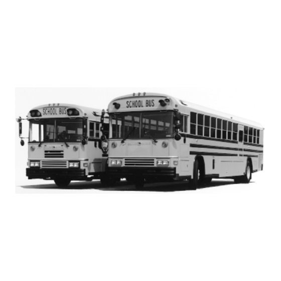
- Page 1 ALL AMERICAN Owner's Manual...
-
Page 2: Table Of Contents
Shutters ..............79 Circuit Breakers ............19 Cooling System ............79 Mirrors & Mirror Adjustment ......... 20 All American Pitman Arm ........79 Emergency Equipment ..........22 Front Axle Stop & Steering Gear Emergency Exit ............24 Automatic Poppet Adjustments ......80 Transpec Safety Vent .......... -
Page 4: Introduction
It explains the various features and controls which should be familiar to the operator before he/she attempts to drive the unit and will help keep your Blue Bird All American in top operating condition and help extend its service life. -
Page 5: Forward
This Operator’s Manual provides some general, as well as specific, information regarding safe operation and maintenance of your Blue Bird bus. It does not address all items or situations that may arise and is not a substitute for proper driver and mechanic training. The exercise of care, common sense and good driving and working practices are required for safe operation. -
Page 6: Inspection
The Body Serial and Service Number Plate is located on BLUE BIRD the front upper inner panel above the windshield. Refer to the data on this plate for registration purposes or for replace- BODY CO. ment part information. FORT VALLEY, GEORGIA BODY NO. - Page 7 Look inside the bus: • Seat, floor - housekeeping. Steps and aisle clear? • Emergency exits open & close, rear door, windows. • Emergency equipment. • Fire extinguisher pressure. • First aid kit. • Driver’s area - windshield, windows clean? •...
-
Page 8: Operator's Compartment
OPERATOR’S COMPARTMENT 1. Driver’s seat. 2. Switch panel. 3. Windshield wiper switch - op- erates windshield wiper & washer. 4. Driver’s window defroster - di- rects air flowto driver’s window 5. Driver’s foot warmer, window defroster control - controls flow of air. -
Page 9: Tilt & Telescoping Steering
TILT & TELESCOPING STEERING To adjust steering wheel position, use the tilting lever located on the left side of steering mounting bracket. Press lever downward to unlock steering column. Move column to one of four positions and release lever. To raise or lower the steering wheel position, pull up on the tilting lever. -
Page 10: Switch Panel
BLANK BLANK DOME DOME DOME CL LAMPS WL PILOT WL PILOT WL MANUAL BLANK WL MASTER 7. Heater Pump BLUE BIRD BODY COMPANY 8. Auxiliary Heater BLANK BLANK BLANK BLANK BLANK 9. Front Heater 10. Defroster US HTR US HTR... -
Page 11: Seats & Seat Belts
Keep feet and other items away from height adjustment handles and pedals while vehicle is in motion. DRIVER'S SEAT LUBRICATION NOTE: For optional Blue Bird driver's seat. Moving parts of the driver’s seat require lubrication for ease of operation, as well as, longevity of the seat and prevention of excessive wear. - Page 12 SEAT INSPECTION & MAINTENANCE Blue Bird seats are built to meet Federal Motor Vehicle Safety Standards. In order to provide even safer passenger transportation, the following guidelines should be met. 1. Inspect and retighten seat leg and wall side mounting bolts every 90 days.
- Page 13 SEAT CARE AND CLEANING It is imperative that the interior of the bus be kept clean and seats are an important part of this mainte- nance. Regular cleaning and care will prolong the life of the seats and improve the general appearance. Everyday dirt and soil - Most everyday soil and dirt may be removed with a soap and water solution.
-
Page 14: Electrical Systems
All passenger seats must have a seat or barrier in front of it to provide compartmentalization required by Federal Motor Vehicle Safety Standards. As you reconfigure your bus, you may need additional barriers. Barriers are available from Blue Bird Body Company Part Sales. FEDERAL STANDARD REQUIREMENTS FOR TRACK SEAT PLACEMENT... -
Page 15: Light Bulb Data
6. Always be sure ground straps are replaced when any work is done on engine components. The alternator must have at least a six (6) gauge strap. The engine must have one strap, engine block and transmission. (Use bolt that mounts transmission to rear face of engine block.) Allow slack loop for engine motion. -
Page 16: Doran Warning Light Monitor
REPAIR PROCEDURE NOTE: Field repair is not intended for monitors covered by Blue Bird Body Company warranty. Inoperative monitors under warranty should be returned to Blue Bird Body Company for repair or replacement under the terms and conditions of warranty for electrical parts. - Page 17 Reinstall monitor in bus, making sure battery is disconnected and that wires are recon- nected to the monitor in the same order as shown in chart on page 18. If additional instructions are needed after following the above procedure, contact Blue Bird Body Company. DIAGNOSIS...
- Page 18 The cause of an inoperative LED will generally be found in monitor and bus circuits other than at the LED; however, if an LED itself is known to be inoperative, contact your usual Blue Bird service parts source for special handling of replacement LED’s.
- Page 19 Monitor Connection Lamp Function Model: A B C D E RED WARNING LAMP RIGHT INPUT X X X X RED WARNING LAMP RIGHT FRONT OUTPUT X X X X BATTERY RED WARNING LAMP RIGHT REAR OUTPUT X X X X AMBER WARNING LAMP RIGHT INPUT AMBER WARNING LAMP RIGHT FRONT OUTPUT AMBER WARNING LAMP RIGHT REAR OUTPUT...
-
Page 20: Circuit Breakers
CIRCUIT BREAKERS Body and chassis circuits are protected by circuit breakers located in a side mounted electrical box below driver’s window. If a current overload or short should occur in any body circuit, it will trip the circuit breaker. If a short occurs and the circuit breaker breaks, the circuit breaker will reset itself when the element cools in about 15 seconds. -
Page 21: Mirrors & Mirror Adjustment
Right front convex crossview and right and left front convex rear- view mirrors are required equipment on all All American Forward Engine and Rear Engine Type (D), buses. Left front convex crossview mirrors are also available. - Page 22 judging the size or distance of a person or object seen in a convex mirror. Wait until you can view the person or object in a flat mirror or direct view to determine their size and distance. EXTERIOR REARVIEW Standard equipment on all school buses is comprised of 4 outside rearview driving mirrors. (2 per side), and 2 elliptical crossview mirrors, (1 per side).
-
Page 23: Emergency Equipment
FIRST AID BLUE BIRD BODY CO. FIRE EXTINGUISHER* The fire extinguisher is normally located to the left of the driver's seat, or on the righthand side of the hood ledge near the stepwell when space limitations dictate. - Page 24 triangular warning device, encased fusees, fire extin- guisher, fire axe and wrecking bar are located in the front of the bus body in the center compartment at the floor depending on the options. Your unit may be equipped with a 2 3/4, 4 1/2, 5 FIRST AID or 6 pound fire extinguisher.
-
Page 25: Emergency Exit
EMERGENCY EXITS Emergency exits are clearly identified by the words “Emer- gency Exit.” Operating instructions EMERGENCY DOOR are written close to each exit. Some SEE INSTRUCTIONS BELOW units are equipped with an audible alarm device signifying an emer- EMERGENCY EXIT INSTRUCTIONS BELOW gency exit is unlatched or open. -
Page 26: Wheelchair Lifts
(NORMALLY OPEN) STOP ARMS Stop arms are required on Blue Bird All American school buses per FMVSS 131. Stop arm assemblies are purchased as a kit; many different kits are available with blades to meet all state requirements. The stop arm is located on the left-hand side of the body under the driver’s window. - Page 27 With the electric stop arms the manual switch activates the control relay of the stop arm. Optionally, the stop arm may be activated by the warning lamp system. The following preventive maintenance procedures should be followed for the electric stop arm.
- Page 28 ELECTRIC STOP SIGNS AND CROSSING ARMS: In order to troubleshoot an electric stop sign or crossing arm it is important to first understand how to install the stop signs and crossing arms. The electric installation can be accomplished in two different man- ners.
-
Page 29: Front Access
Problem: Fading to the blade surface. Areas to Check: 1. Steel blades are painted with a red paint, which are prone to bleaching due to the pigments. If the blade becomes faded possible solutions are to repaint or replace the blade. Specialty recommends the replacement of the blade due to the labor savings and cost efficiency. -
Page 30: Access Doors
ACCESS DOORS In order to prolong the life of access door latches, locks and hinges, periodic maintenance should be performed as follows. Once per week, clean and inspect the door hinges and latch mechanisms. Clean with a nonabrasive degreaser or cleanser as required. Every three months lubricate with either a graphite-type lubricant or a spray-type lubricant such as LPS. -
Page 31: Towing Or Pushing
Bumpers provided on Blue Bird buses are designed to protect the vehicle and occupants from front and rear collisions. They are not designed for towing the vehicle. Blue Bird does NOT recom- mend nor approve towing the vehicle by the bumpers. - Page 32 valve is located over the door and stepwell lights are operated by air pressure switches inside the header cover. Door operation by the driver is managed by a simple two-way manually operated valve, and air pressure holds the door either open or closed depending on the position of the valve. The operation speed is adjustable by use of flow control valves at cylinder inlet and outlet.
- Page 33 POWER JACKKNIFE DOOR NOTE: For air diagram, see drawing #0867606 supplied with vendor maintenance documents. The following adjustments and lubrications should be performed on the power jackknife door (Options 0233, 0467 and 0468) to insure its proper operation. 1. Lubricate center hinge with LPS No. 1 type lubricant. 2.
- Page 34 Power Door Push-Pull Valve EMERGENCY RELEASE OPEN Power Door Emergency Release Valve Located on the Door Header Cover. ELECTRIC OUTWARD OPENING DOOR The electrically operated outward opening door has a linear actuator that moves a lever attached to the front door. To open the door, hold the spring loaded switch in the driver's area in the "open" position until the door stops moving.
-
Page 35: Vandal Locks
VANDAL LOCKS ENTRANCE DOOR To activate the optional electric entrance door vandal lock, pull the door to a full closed position from the outside of the vehicle. When this is done, the vandal lock is activated. To deactivate the lock insert key in lock located at right of the door (forward of door) and turn. -
Page 36: Keeping Your Vehicle Looking New
EMERGENCY DOOR The emergency door vandal lock has a lock cylinder which is placed in the lock to make the emergency door inoperable. When the cylinder is in place in the lock, the coach can- not be started. To complete the igni- tion circuit, the lock cylinder must be removed from the lock and placed in the receptacle at the side... -
Page 37: Engine Access
FINISH DAMAGE Any stone chips, fractures or deep scratches in the finish should be repaired promptly. Exposed metal will corrode quickly and may develop into a major repair expense. FLOORS AND FLOORCOVERING It is imperative that the interior of the bus be kept clean and floorcovering is an important part of this maintenance. - Page 38 3. When handle is reversed, grip and pull to open door. 4. After closing press in the larger portion of the latch untill it snaps to lock into position. 1. Engine Compartment Lights. 8. Heater Gate Valve. Not indicated on Cummins 8.3. 2.
-
Page 39: Heaters
HEATERS GENERAL INFORMATION Blue Bird heaters are hot water type which depend on heat generated by the engine for their function. Heat from the engine is picked up by the engine coolant which is pumped through the heaters inside the body and back into the engine. - Page 40 4. Remove heater from seat frame, pull it away from the wall and remove hose connections. 5. Disconnect motor wires and remove heater from bus for further disassembly. DEFROSTING Windshield fogging and frosting is caused by warm, humid air coming in contact with a cold windshield, which causes the moisture in the air to condense and possibly freeze if the windshield is cold enough.
- Page 41 DEFROSTER FAN LOCATIONS Opt. 0525 - On the All American with deluxe door control and standard manual control, the fan is mounted on the door control bracket. With power door controls, the fan is mounted on the dash cover.
- Page 42 Using a suitable container to catch coolant, run engine between 2,000 and 3,000 RPM, loosen bleeder valve located in heater hose return line. Bleed air and coolant through bleeder valve until air is elimi- nated from heater system. (Stop bleeding when continuous stream of coolant comes from bleeder valve.) Note: It will be necessary every few moments to refill the radiator or surge tank.
- Page 43 HEATER CUT OFF VALVE LOCATION (AAFE) Valves No. 2 & 3 are to be used STANDARD VALVING to isolate the heater system from the engine in case a leak occurs PRESSURE LINES RETURN LINES VALVES UNITS WITH FRONT HEATER ONLY UNITS WITH AUXILIARY HEATER within the system while bus opera- tion must be continued, or for re-...
- Page 44 Hoses are installed with as few joints as possible so as to prevent the possibility of leaking joints. If a portion of hose becomes damaged, a new piece of hose can be spliced in by use of 4 inch brass tube (Blue Bird part #1701903), and hose clamps.
- Page 45 AARE WATER FLOW WATER FLOW AAFE THIS LINE IS NEAREST THE CENTERLINE BODY. AUXILIARY PUMP GOES IN THIS LINE. 50 OR 80 50 OR 80 UNDERSEAT UNDERSEAT HEATER HEATER REAR FRONT TRIM HEATER CLAMP ACCESS OPENING 50 OR 80 50 OR 80 UNDERSEAT UNDERSEAT HEATER...
-
Page 46: Windows & Windshields
WINDOWS AND WINDSHIELDS WINDSHIELD GLASS REPLACEMENT The windshield is one of two types: four-piece flat or two piece curved. 1. Remove vertical filler strip in glazing rubber on each side of bro- ken glass; remove horizontal filler strip in glazing rubber on top and bottom of broken glass. - Page 47 4. On bottom glass, simply pull aluminum channel off top and bottom of glass. 5. To remove glass from top part of window, remove 6 screws holding frame around glass. 6. Reassemble window by reversing above procedure. 7. Apply weather seal caulking around window frame to prevent leaking.
- Page 48 WARNING: When replacing broken or damaged glass, use extreme care at all times to prevent personal injury. This includes the use of proper replacement parts, tools and personal protective equipment, such as gloves and safety goggles. REAR VISION GLASS REPLACEMENT 1.
- Page 49 Glass Replacement Procedure 1. To remove push-out transit sliding window, release window lever (1) located inside the bus at the bottom of each push-out window. Remove hinge screws (2) on outside of body. Lift and pull window out of sec- tion.
-
Page 50: Windshield Wipers
Remove the cap nuts, which secure the wiper arm and idler arm to the wiper and idler shaft, respectively. Remove the wiper arm and place new arm (Blue Bird No. 0348177) over wiper shaft and make sure the new arm is replaced in the same position as the old arm was removed. -
Page 51: Lower Side Panel Repair Procedure
1/2 inch of the replacement panel is under the rub rail. Install Cherry SSPV 86 blind rivets, Blue Bird P/N 0888222 on 3 1/2 inch centers through the rub rail lower flange and the new and old side panel. - Page 52 1. Remove the two securing nuts and ro- tate tire out of holes. 2. Through access hole, insert lug wrench, placing socket over hex head on shaft and turn clockwise and disengage ratchet. 3. Slowly lower tire by turning counter- clockwise.
-
Page 53: Tires, Wheels & Rims
Both the tubeless type and tube type tires are used on the All American. The tubeless tires are mounted on 15 degree drop-center rims and wheels. The tube type tires are mounted on two-piece flat base rims or wheels or three-piece flat base rims or wheels. - Page 54 carrying requirements of each vehicle should also be determined before selecting the proper tire/wheel com- bination. Always remember that the weakest weight carrying component vehicle (i.e., tire, wheel, axle, bear- ings, etc.) determines it overall maximum and safe load carrying capacity for the vehicle. WARNING: There have been many reported injuries and deaths from improper handling of wheels and rims.
-
Page 55: Jacking Instructions
LUG WRENCH AXLE CAUTION: Bumpers provided on Blue Bird buses are designed to protect the vehicle and occupants from front and rear collisions. However, the AAFE may be lifted by front and rear bumpers with the use of bumper jacks. NOTE: All instructions 1 thru 5 must be followed. - Page 56 STARTING WITH BOOST CABLES WARNING: Batteries give off flammable fumes that can explode. Prevent sparks near the batteries. They could cause vapors to explode. Do not allow battery cable ends to contact each other or the engine. CAUTION: Do not smoke when observing the battery electrolyte levels. Electrolyte is an acid and can cause personal injury if it contacts skin or eyes.
-
Page 57: Noise Emissions Warranty
Blue Bird Body Company warrants to the first person who purchases this vehicle for purposes other than resale and to each subsequent purchaser that this vehicle, as manufactured by Blue Bird, was designed, built and equipped to conform at the time it left Blue Bird control to all applicable U.S. EPA Noise Control Regula- tions. -
Page 58: Fuel & Lubricant Requirements
Blue Bird. Defects in design, assembly or in any part, component or system of the vehicle as manufactured by Blue Bird, which at the time it left Blue Bird control, caused noise emissions to exceed Federal standards, are covered by this warranty for the life of the vehicle. - Page 59 (Compressed Natural Gas) must be inspected every three (3) years in accordance with NGV-2 specifications. The owner/operator should be aware that cylinder expiration date is fifteen (15) years after date of cylinder manufacture and that cylinders must be replaced. This testing and certification is not covered by Blue Bird warranty.
- Page 60 FUEL SYSTEM DESCRIPTION The fuel system begins with DOT certified tanks to hold compressed natural gas (CNG) up to 3600 psi, corrected to standard day temperature. The tanks are high strength aluminum wrapped with fiberglass for further strength. The fuel exits the tank in route to the engine through manually controlled shutoff valves. These include an integral pressure relief valve consisting of a combination rupture disk (for pressure) and fuse plug (for temperature) to vent the contents of the tank should high pressure and high temperature occur, such as in a fire.
- Page 61 CAUTION: It is the owner's/operator's responsibility to insure that clean, quality fuel is used to prevent damage to the fuel system components and power plant. Damage caused by poor quality fuel is not covered by Blue Bird warranty.
- Page 62 COMPRESSED NATURAL GAS FILTERS Particulate and coalescer type filters are installed in Blue Bird CNG fuel systems. The primary filter is of stainless steel construction and is located at the fill point. This filter can be checked for contamination by closing main shutoff valve on frame and then relieving pressure which is trapped between the check valve in the fill nozzle and the main system check valve.
- Page 63 The National Fire Protection Association has recommended guidelines for CNG refueling systems. State and local regulation regarding NGV refueling may preclude economic feasibility of indoor refueling (such as in New York City). However, the significance of this issue may diminish if increased experience with fuel leads to less stringent regulations.
- Page 64 FUEL TOXICITY AND SAFETY Natural gas is a nontoxic gas. It is flammable under proper conditions. Additionally, it can cause suffoca- tion if enough oxygen is displaced. LNG has the added safety concern of being a cold (-260 F) liquid under pressure.
- Page 65 STARTING PROCEDURE Make sure that the main shutoff valve and at least one tank valve are open. The fuel gauge shows empty if no fuel is available to the mixer. Check the tank and main fuel shutoff valves if no fuel is indicated on the fuel gauge.
-
Page 66: Manual Five Speed Transmission
MANUAL FIVE SPEED TRANSMISSION The standard transmission used in the AAFE is a five-speed Synchro-Mesh trans- mission. Refer to the gearshift knob for proper shift sequence. CAUTION: The shift linkage has been improved for this model, resulting in a new shift pattern. When trying to engage the shift lever into first or reverse gear, it will be neces- sary to follow these procedures: Disengage the clutch and move the lever into first or reverse gear. - Page 67 Adjust the mechanical modulator per the following procedure: 1. With the modulator cable disconnected at the engine, rotate fuel control lever on the engine to full throttle position. 2. Adjust modulator slip joint to push cable until the cable comes within 1/8 inch of bottoming, when throttle is wide open.
- Page 68 Neutral, seek service immediately. Neutral is also used during stationary operation of the power takeoff (if your vehicle is equipped with a PTO). The SELECT indicator will display Neutral and the MONITOR will display Neutral. WARNING: Do not allow your vehicle to coast in Neutral. This practice can result in transmission dam- age.
- Page 69 Observe the following cautions when using output retarder. • Apply and operate the retarder with engine at closed throttle only. • Do not use the retarder when road surfaces are slippery. Do not apply retarder control or de-energize the system at the master control switch. •...
- Page 70 COLD WEATHER STARTS MD 3060 Most World transmissions are programmed to restrict full operation until specific temperatures are reached. Refer to the following chart for temperature restrictions. Sump Oil CHECK Operation Temperature TRANS. light -32 deg.C (-25 deg.F) Neutral only and below -31 deg.C (-24 deg.F) Neutral, First,...
-
Page 71: Two Speed Rear Axle Shift Control
CAUTION: The engine should never be operated for more than 30 seconds at full throttle with the trans- mission in gear and the vehicle not moving. Prolonged operation of this type will cause the transmission oil temperature to become excessively high and will result in severe overheat damage to the transmission. If the transmission overheats during normal operation, check the oil level in the transmission. - Page 72 AXLE-ONLY UPSHIFT An Axle-only Upshift is as follows: When the shift is needed, pull the axle shift button up. Release the accelerator pedal to break torque. The axle will shift, and you can resume acceleration. The axle will not shift until the accelerator pedal is released, because torque creates a binding action on the sliding clutch gear.
- Page 73 SPLIT UPSHIFT An axle downshift with a transmission upshift is also called a Split Upshift. A Split Upshift is as follows: When the shift is needed, depress the clutch and move gear shift lever to next gear. Keep the clutch down and push the axle shift button down.
-
Page 74: Air Brakes
AIR BRAKES A coach equipped with a dual air brake system consists of separate complete systems for the front and rear service brakes. A separate reservoir and air gauge is provided for each of these systems. A dual treadle valve is provided for operating the service brake system. In addition to providing excellent service brake performance, this dual brake system is equipped with safety features which allow the driver to use the emer- gency stopping system through the service brake treadle valve. - Page 75 SHRADER VALVE The coach is equipped with a Schrader valve which is located at SHRADER VALVE Shrader Valve the end of the wet tank. It allows the air brake reservoir to be charged with a common type air hose normally used by service stations and garages.
-
Page 76: Hydraulic System
NOTE: Set up of manual and automatic slack adjusters must be performed with full system air pressure applied to the spring chamber. Also, follow manufacturer’s procedure for adjusting manual and automatic slack adjusters. WARNING: To safely disassemble the spring chamber, follow the procedures outlined in MGM Service Manual No. - Page 77 HYDRAULIC SYSTEM - TROUBLESHOOTING 1. Hydraulic fan will not run. A. Check hydraulic oil level in reservoir. (Sight glass) B. Check fan motor for free rotation, fan motor should rotate freely. If not rebuild or replace fan motor. CAUTION: Engine should be shut off when checking fan motor for free rotation. C.
-
Page 78: Hydraulic Clutch Controls & Adjustment For Manual Transmissions
5. Remote electric Hayden cooling fan will not run. (Cat 3116 only) A. Disconnect wires from temperature control switch and start engine. If fan runs with wires discon- nected, the temperature control switch is at fault. Replace switch. B. If fan does not run with wires disconnected, check Hayden Fan Relay on Hayden Fan Override Relay for voltage, shorts or open circuits. -
Page 79: Radiator Fans
The purpose of the slave cylinder push rod adjustment is to provide adequate travel of the clutch release bearing to insure; (1) Complete clutch disengagement when the clutch pedal is fully depressed. (2) Complete clutch engagement and clutch release bearing clearance when the clutch pedal is fully released. The clutch slave cylinder push rod illustration below shows the adjustment procedures for the type of adjusting mechanism used with slave cylinders installed on Forward Control Coaches. -
Page 80: Shutters
On vehicles used in stop-and-go service, such as the Blue Bird All American, engine hoses deteriorate more rapidly; therefore it is important to inspect all such hoses frequently. Hoses which are worn, chafed, hardened or cracked must be replaced before a leak develops. -
Page 81: Front Axle Stop & Steering Gear Automatic Poppet Adjustments
3. After removing the pitman arm nut and bolt, the pitman arm boss must be spread in order to loosen the pitman arm for removal from the shaft. Spreading the boss may be accomplished by using the correct size Allen wrench, a chisel or a pitman arm spreader. If the pitman arm cannot be removed from underneath, there is a small hole in the floor that may be used for access, by removing the four screws in the access plate. -
Page 82: Wheelbearing Adjustments
If it becomes necessary to shorten the turning radius, the steering gear poppets must be adjusted manu- ally by doing the following. Read the section on special poppet valve manual readjustment in the TAS65 Service Manual before proceeding. 1. Set axle stops for correct turn. 2. -
Page 83: Ridewell Vehicle Air Suspension
JAM NUT TORQUE SPECIFICATIONS AXLE TYPE Nut Size / Design Torque Specification Front (Non-Drive) Less than 2 5/8" 200 - 300 ft. lbs. 2 5/8" and over 250 - 400 ft. lbs. Drive Axles Less than 2 5/8" 200 - 300 ft. lbs. No Lockwasher Used 2 5/8"... - Page 84 IMPORTANT NOTE: Most trouble or failures do not put the suspension out of operation. Road repairs are not necessary for anything less than a major breakdown. Temporary steps can be taken to continue careful operation for many miles until such time it is convenient to make repairs. Safe air brake pressure of 65 PSI is automatically maintained by a brake protection valve in the event of an air loss due to a failure in the suspen- sion air system.
- Page 85 BRASS AIR FITTING CONNECTIONS BRASS PIPE FITTING - SIZE *RECOMMENDED TORQUE 1/8 N.P.T. 4 Ft. Lbs. 1/4 N.P.T. 10 Ft. Lbs. NOTE: Use Loctite or equivalent sealer at brass pipe fitting connections. Do not allow sealer to enter any valve body or connection. LUBRICATION Your Ridewell Suspension requires no lubrication at any time.
- Page 86 TROUBLE-SHOOTING IMPORTANT- Most trouble or failures do not put the suspension out of operation. Road repairs are not necessary for anything less than a major breakdown. Temporary steps can be taken to continue careful opera- tion for many miles until such time it is convenient to make repairs. Broken or worn shock absorbers, rubber bushings, or other components should be replaced as soon as conveniently possible.
-
Page 87: Scheduled Maintenance
SCHEDULED MAINTENANCE MONTHLY OR 1,000 MILES • Grease safety barrier latch on Braun wheelchair lift. • Lubricate roof hatch weatherseals & lock mechanisms. • Inspect all emergency equipment mounting fasteners. • Lubricate window latches and slides. • Lubricate hinge pin on entrance doors. •... - Page 88 6 MONTHS OR 6,000 MILES • Check lubricant level in rear axle. • Inspect rear axle vent. • Check power steering fluid level. • Lubricate steering drag rod. • Check single and double check valves. • Lubricate spring pin. • Inspect alternator. •...
- Page 89 • Inspect shocks. • Inspect suspension hanger bracket to frame fastener torque. • Inspect quick starting aid. • Inspect engine block heaters. • Pressure test engine cooling system. • Check radiator fan and motor. • Inspect electrical fuel transfer valves. •...
-
Page 90: Maintenance Service Keys
MAINTENANCE SERVICE KEYS AAFE MAINTENANCE SERVICE KEY AARE MAINTENANCE SERVICE KEY... -
Page 91: Quick Reference Maintenance Charts
QUICK REFERENCE MAINTENANCE CHARTS CUMMINS ENGINE MAINTENANCE CHART Service Intervals * Months / Miles Whichever Occurs First *Service Intervals to be performed on a continuing basis. Example: 1 / 3,000 means every month or every 3,000 miles. Operation General Instructions Check Engine Oil Level See Cummins Book. -
Page 92: John Deere 8.1 Cng Engine Maint. Chart
JOHN DEERE 8.1 CNG ENGINE MAINTENANCE CHART Service Intervals * Months / Miles Whichever Occurs First *Service Intervals to be performed on a continuing basis. Example: 1 / 3,000 means every month or every 3,000 miles. Operation General Instructions Check Engine Oil Level Daily See PowerTech 6081 CNG Engine Book. -
Page 93: Suspension Maintenance Chart
For Ridewell information, see pages 82. Check torque before vehicle is placed in First 1,000 & 3,000 miles service and at regular intervals. ENGINE BELT CHART A-3000 ENGINE BELTS BLUE BIRD No. VENDOR No. BELT DIMENSION Caterpillar 3116T & 3116TA Fan / Alt. 1454636 K080580 8 Groove x 58.00... -
Page 94: Axle Maintenance Chart
AXLE MAINTENANCE CHART Service Intervals * Months / Miles Whichever Occurs First *Service Intervals to be performed on a continuing basis. Example: 1 / 3,000 means every month or every 3,000 miles. Operation General Instructions REAR AXLE Check Lubricant See Rockwell Int. Field Maintenance Manual. Keep oil to level of filler plug. Drain &refill at first 1,000 to 3,000 miles and then at recommended intervals. -
Page 95: Brake Maintenance Chart
BRAKE MAINTENANCE CHART Service Intervals * Months / Miles Whichever Occurs First *Service Intervals to be performed on a continuing basis. Example: 1 / 3,000 means every month or every 3,000 miles. Operation General Instructions AIR BRAKE SYSTEM Air Brake Operation See page 73. -
Page 96: Chassis Component Maintenance Chart
CHASSIS COMPONENT MAINTENANCE CHART Service Intervals * Months / Miles Whichever Occurs First *Service Intervals to be performed on a continuing basis. Example: 1 / 3,000 means every month or every 3,000 miles. Operation General Instructions ACCELERATOR SYSTEM (AAFE) Inspect Cable Check cable for proper connection, cracking, abrasion or deterioration. -
Page 97: Body Component Maintenance Chart
BODY COMPONENT MAINTENANCE CHART Service Intervals * Months / Miles Whichever Occurs First *Service Intervals to be performed on a continuing basis. Example: 1 / 3,000 means every month or every 3,000 miles. Operation General Instructions OUTWARD OPENING DOOR Adjust Door Linkage Rod As Required Adjust door linkage rod for proper open/closed position. -
Page 98: Wheelchair Lift Maintenance Chart
BODY COMPONENT MAINTENANCE CHART Service Intervals * Months / Miles Whichever Occurs First *Service Intervals to be performed on a continuing basis. Example: 1 / 3,000 means every month or every 3,000 miles. Operation General Instructions HEATERS Check Heater Hoses Check hoses for kinks, cracks or other visible signs of damage. -
Page 99: General Data
GENERAL DATA DIMENSIONS: Headroom - 74" to 77" Exterior height - approximately 118" to 121" Exterior height w/AC - add 16" Exterior width - 96" Exterior length w/AC - add 7" Interior width - 90 3/4" FLUID CAPACITIES Engine Transmission Fluid Crankcase Oil Cooling Manual... -
Page 100: Index
Drivelines ..............95 Spring Brake Application ........75 Electrical System ............. 95 Manual Transmission ..........95 All American Pitman Arm ........79 Allison Automatic Transmission ......65 Circuit Breakers ............19 Accelerator Control ..........68 Allison Transmission Cable Adjustments ... 65 Coach Identification .......... - Page 101 Doors ................30 Front Axle Stop Adjustments ........ 79 Electric Outward Opening Door ......33 Jackknife Door ............30 Fuel & Lubricant Requirements ......57 Power Door ............. 32 Diesel Fuel ............... 57 Power Jackknife Door ..........31 Recommended Lubricant ........57 Outward Opening Air Door .........
- Page 102 Keeping Your Vehicle Looking New ....35 Driver's Seat Belt w/Shoulder Harness ....11 Finish Damage ............36 Driver's Seat Lubrication (Blue Bird) ....10 Floors & Floorcovering .......... 36 Passenger Seat Belt Operation ......11 Foreign Material Deposits ........35 Seat Belt Inspection &...
- Page 103 Transpec Safety Vent ..........24 Maintenance Cautions ........... 24 Service & Repairs ............ 25 Two Speed Rear Axle Shift Control ..... 70 Axle Only Downshift ..........71 Axle Only Upshift ..........71 Split Downshift ............72 Split Upshift ............72 Vandal Locks .............
- Page 104 Part Number: 1974526 Blue Bird Corporation • P.O. Box 937 • Fort Valley, GA 31030...
Need help?
Do you have a question about the ALL AMERICAN and is the answer not in the manual?
Questions and answers
Fuel tank capacity on a 1995 mini blue bird
The 1995 Blue Bird All American mini bus may be equipped with a center-mounted 60-gallon fuel tank.
This answer is automatically generated