Table of Contents
Advertisement
Quick Links
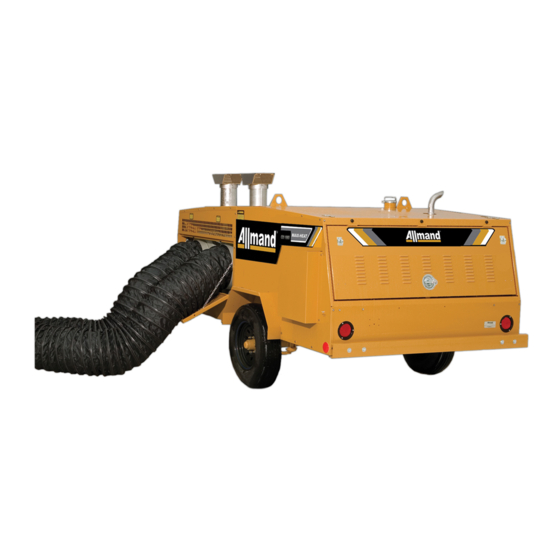
OPERATOR'S AND PARTS MANUAL
SEPTEMBER 2011
MAXI-HEAT
SERIES
®
MODEL MH-1000
Beginning with Serial Number 0001MXH09
ALLMAND BROS. INC
P.O. BOX 888
HOLDREGE, NE 68949
PHONE: 308/995-4495, 1-800/562-1373
FAX: 308/995-5887
PARTS FAX: 308/995-4883
®
MAXI-HEAT
SERIES
REV H-1 IDF 500
For Parts and Updates visit Allmand on the Web at www.allmand.com
80025368_B
Advertisement
Table of Contents

Related Manuals for Allmand MAXI-HEAT SERIES MAXI-HEAT MH-1000


Summary of Contents for Allmand MAXI-HEAT SERIES MAXI-HEAT MH-1000
- Page 1 Beginning with Serial Number 0001MXH09 ALLMAND BROS. INC P.O. BOX 888 HOLDREGE, NE 68949 PHONE: 308/995-4495, 1-800/562-1373 FAX: 308/995-5887 PARTS FAX: 308/995-4883 ® MAXI-HEAT SERIES REV H-1 IDF 500 For Parts and Updates visit Allmand on the Web at www.allmand.com 80025368_B...
-
Page 3: Table Of Contents
TABLE OF CONTENTS OPERATORS MANUAL Inspection Check List..............3 Introduction..................4 Safety Decals................. 5 Set-up Procedure................8 Specifications................. 9 Serial Number Location..............9 Fuel and Lubricating Oil............... 10 Starting Procedure................11 Maintenance and Towing Instructions.......... 12 Troubleshooting Heaters.............. 13 Electrical Schematics..............17 Ductwork Installation Options............ -
Page 4: Inspection Check List
INSPECTION CHECK LIST PREPARING THE MAXI-HEAT FOR DELIVERY OR RENTAL ® The Allmand Maxi-Heat requires service as well as proper operation in order to provide the performance and safety for which it was designed. Never deliver or put a machine into ser- vice with known defects or missing instructions or decals. -
Page 5: Introduction
INTRODUCTION This manual provides the information necessary for the safe operation and ® maintenance of the Allmand Maxi-Heat Specific operating details and specifications are contained in this publication to familiarize the operator and maintenance person with the correct and safe procedures necessary to maintain and operate this equipment. Take time to read this book thoroughly. If you are uncertain about any of the information contained in this manual, contact your dealer for clarification be- fore operation of the machine. -
Page 6: Safety Decals
SAFETY DECALS Refer to these reperesentations SAFETY WARNING! of the safety warning decals used on the Maxi-Heat to insure correct ordering if replacing becomes neces- ALWAYS REPLACE ANY SAFETY AND INSTRUCTION DECALS THAT BECOME DAMAGED, PAINTED, OR OTHERWISE ILLEGIBLE. PART NO. 090023 PART NO. - Page 7 SAFETY DECALS HEATER OPERATING INSTRUCTIONS Inside Rear Door PART NO. 09007 Inside Rear Door PART NO. 090304 FAN SHUTDOWN INSTRUCTIONS Inside Rear Door Inside Rear Door...
- Page 8 SAFETY DECALS PART NO. 100910 CAUTION 1). NEUTRAL BONDED TO FRAME 2). MACHINE TO BE GROUNDED IN ACCORDANCE WITH REQUIREMENTS AS OUTLINED BY LOCAL INSPECTIONS AUTHORITIES 3). TURN OFF ALL POWER BEFORE SERVICING 4). THE REQUIREMENTS OF LOCAL AUTHORITIES HAVING JURISDICTION SHALL BE FOLLOWED 5).
-
Page 9: Setup Procedure
® MAXI-HEAT SETUP PROCEDURE The Frost Fighter heater units need to be set up for each operation and tuned to operate efficiently depending on the altitude of intended use. As you go up in elevation, the air gets thinner. As the air gets thinner the ability to burn or consume a certain amount of fuel is diminished. When you move the machine to a different elevation you may need to change the nozzle size and air settings to get a clean efficient burn. The nozzle size is determined by the number of gallons per hour number (GPH). A number is stamped on the nozzle indicating the amount of fuel that the nozzle will deliver to the burning chamber. -
Page 10: Specifications
® MAXI-HEAT SETUP PROCEDURE 6. Check igniter tips for correct location for the unit you are setting up. Adjust if necessary. (see owners manual) For the IDF 500: · 5/32 apart · ¼” above center of nozzle · 1/8” in front of nozzle 7. Re-install the fuel rail, hook up fuel lines etc. 8. Restart the heater and check the flue gas for smoke using the True-Spot Smoke Tester. 9. If you get a smoke test reading in the 2 to 3 range you will be ready to fine tune the burner to achieve a #1 or possibly a 0 on the smoke scale. -
Page 11: Fuel And Lubricating Oil
FUEL AND LUBRICATING OIL NOTE: In testing this engine at the factory, the The temperatures mentioned in the table are manufacturer uses on oil for moderate and low tem- the ambient temperatures at the time the engine is peratures. This oil is specially formulated to assist started. -
Page 12: Starting Procedure
STARTING PROCEDURES BEFORE STARTING: HEATER STARTING: 1.Fill the engine with the specified grade and quan- NOTE: Circuit breakers for heaters must be switched tity of lubricating oil to correct level (check to the ON position. dipstick). 2.Ensure there is an adequate supply of fuel. NOTE. Allow engine to come to full RPM and warm 3.Ensure that the air cleaner is firmly attached and up before starting heaters. -
Page 13: Maintenance And Towing Instructions
MAINTENANCE AND TOWING INSTRUCTIONS NOTE: Service intervals have been estab- NOTE: DO NOT TAMPER WITH UNIT. HAVE A lished for operation under normal conditions. COMPETENT SERVICEMAN MAKE ANY ADJUST- Where equipment is operated under severe MENTS. conditions(very dusty, extreme cold, etc.) af- fected items should be serviced more frequently. -
Page 14: Troubleshooting Heaters
CLEANING PROCEDURE... - Page 15 CLEANING PROCEDURE...
- Page 16 TROUBLESHOOTING Electrode Adjustments...
- Page 17 TROUBLESHOOTING...
- Page 18 TROUBLESHOOTING...
- Page 19 TROUBLESHOOTING...
- Page 20 TAILLIGHT WIRING SCHEMATIC...
-
Page 21: Electrical Schematics
® MAXI-HEAT ELECTRICAL SCHEMATIC... - Page 22 CONTROL BOX AND GEN SET WIRING 30A 30A 120 VAC 120 VAC FUEL CIRCUIT SCHEMATIC...
- Page 23 ENGINE WIRING SCHEMATIC ISUZU 3CE1 ENGINE...
- Page 24 ENGINE WIRING SCHEMATIC CAT C1.5 ENGINE...
-
Page 25: Ductwork Installation Options
® MAXI-HEAT DUCTWORK INSTALLATION OPTIONS Duct ready for installation on heater using Illustration of lock pin and arrow on 16” slip lock 16” Slip-Lock Connectors (pn 848974) connector (pn848974) for duct installation 16” screw clamp (pn848176) used here to attach duct (pn848172) Duct (pn848172) installed on connecting band Connecting Band (pn848976) for connecting multiple (pn848976) with 16” screw clamp (pn848176) hose lengths... - Page 26 Installation Instructions for Installing the Slip-Lock Duct Connectors (PN #848974) Heater Section – Inner Ring 1. Line up the receiver section (ring with slots) inside the heater flange and slide it in to where the small rounded ridge (approximate center of connector ring) is just inside the outer edge of the heater flange. This leaves 11/16” of this inner ring exposed and will allow the compartment door to close freely. Note: Make sure that this alignment remains constant all the way around the outer edge of the flange. 2. Mark the locations of the (3) 3/16” holes and remove the receiver section from the heater flange. Using a center punch, make a dimple in the center of each mark and drill each hole out using a 3/16” drill bit. 3. Re-install the receiver section into the heater flange and connect it (large head inside heater flange) using a pop-rivet gun and (3) 3/16” pop-rivets.
-
Page 27: Parts Manual
Beginning with Serial Number 0001MXH09 ALLMAND BROS. INC P.O. BOX 888 HOLDREGE, NE 68949 PHONE: 308/995-4495, 1-800/562-1373 FAX: 308/995-5887 PARTS FAX: 308/995-4883 ® MAXI-HEAT SERIES REV H-1 IDF 500 For Parts and Updates visit Allmand on the Web at www.allmand.com... -
Page 28: Trailer Assembly Parts And Accessories
TRAILER ASSEMBLY PARTS AND ACCESSORIES A-1A... - Page 29 TRAILER ASSEMBLY PARTS AND ACCESSORIES A-1B REF# PART# DESCRIPTION 330011 JACK SIDE CRANK 049036 SAFETY CHAIN KIT (2 KITS REQUIRED) 330016* REVERSIBLE HITCH ASSEMBLY 330018* BULLDOG HITCH ONLY 330019 BULLDOG HITCH REPAIR KIT 330039 REFLECTOR, AMBER (2 REQUIRED) 330013 REPLACEMENT LOCK PIN 650236 PLASTIC JACK CAP LEGEND: NS = Not Shown ** = Purchase Locally...
- Page 30 TRAILER ASSEMBLY PARTS AND ACCESSORIES A-2A...
- Page 31 TRAILER ASSEMBLY PARTS AND ACCESSORIES A-2B REF# PART# DESCRIPTION 830030P ROOF PANEL 2 849055P ROOF PANEL 2 (AFTER 0104MXH06) 848403P ROOF PANEL - REAR ISUZU 101239P ROOF PANEL - REAR CAT 848610P ROOF PANEL - CENTER ISUZU 830025P ROOF PANEL - FRONT 849054P ROOF PANEL - FRONT (AFTER 0104MXH06) 848282P SIDE DOOR ASSEMBLY - RIGHT 800229P...
- Page 32 TRAILER ASSEMBLY PARTS AND ACCESSORIES A-3A...
- Page 33 TRAILER ASSEMBLY PARTS AND ACCESSORIES A-3B REF# PART# DESCRIPTION 330055 OUTLET BOX ONLY 330057 OUTLET BOX RUBBER MOUNT 330067 CIRCUIT BREAKER SP, 30 AMP 330067 CIRCUIT BREAKER SP, 30 AMP 352151 INTERIOR LAMP FIXTURE (HEATER COMPARTMENT) 40A 352151 INTERIOR LAMP FIXTURE (ENGINE COMPARTMENT) 830155 POSITIVE DOOR HOLDER 830165 INTERLOCK SAFETY SWITCH 101154 FROST FIGHTER HEATER (2 REQ’D) (IDF500HS after 0001MXH09)
-
Page 34: Heater Assembly Parts And Accessories
HEATER ASSEMBLY PARTS AND ACCESSORIES B-1A... - Page 35 HEATER ASSEMBLY PARTS AND ACCESSORIES B-1B REF# PART# DESCRIPTION 101154 HEATER ASSEMBLY (IDF500HS after 0001MXH09) 101287 HIGH LIMIT SWITCH 200° PROBE 848112 HIGH SWITCH COVER 848154B CAD CELL FLAME DETECTOR 848160 TOGGLE SWITCH 848165 SWITCH RECEPTACLE 848185A OIL PUMP PRIMARY CONTROL 848184 PLASTIC COVER FOR 848185A 102912 GEN.
- Page 36 HEATER ASSEMBLY PARTS AND ACCESSORIES B-2A <16...
- Page 37 HEATER PARTS AND ACCESSORIES B-2B REF# PART# DESCRIPTION 848139B “A” FUEL PUMP 848140 BURNER MOTOR, 1/3 HP 100627 BURNER/BLOWER FAN 848152 OIL DELIVERY TUBE 8” 100626 OIL DELIVERY TUBE 9-1/2”” 848138B BECKETT TRANSFORMER/IGNITOR 848187 FLEX COUPLING 2 3/4” long (1/4” and 1/2” dia. ends) 100618 BURNER ASSEMBLY (IDF 500, CF 800) 848250 HOUSING 100619 AIR TUBE COMBINATION (includes blast tube, electrode assy, and air diffuser) 849007...
- Page 38 ENGINE ASSEMBLY AND CONTROL PANEL-ISUZU C-1A...
- Page 39 22-000324 ALTERNATOR DIODE 22-000299 RADIATOR ISUZU 3CD 103016 AVR BOARD 102859 ISUZU RADIATOR MOUNTING BRACKET 352469 ENGINE BLOCK HEATER (4LE/3CD) 102465 3CD/3CE STARTER 102628 FUMOTO OIL VALVE LEGEND: NS=NOT SHOWN **=PURCHASED LOCALLY ***=CALL ALLMAND FOR INFORMATION @@@=SEE LOCAL ISUZU DEALER...
- Page 40 ENGINE ASSEMBLY AND CONTROL PANEL-CAT C-2A...
- Page 41 848308 GENERATOR MOUNT PLATE 027025 BATTERY CABLE 2 GA 48” 713098 BATTERY CABLE 2GA 36” FUEL PUMP 651192 ENGINE BLOCK HEATER LEGEND: NS = Not Shown ** = Purchase Locally *** = Call Allmand for Information =See Local CAT Dealer...
-
Page 42: Optional Parts And Accessories
OPTIONAL PARTS AND ACCESSORIES D-1A... - Page 43 OPTIONAL PARTS AND ACCESSORIES D-1B PART# 848120 DUCT STORAGE BOX COMPLETE QTY. PART NO. DESCRIPTION 848120 DUCT STORAGE BOX COMPLETE 848121 PNL BOTTOM 848125P PNL TOP 848129 HINGE 848122 PNL FRONT 830232 HASP 848124P PNL SDE LF 848123P PNL SIDE RT 848128P LID WELDED 848954...
- Page 44 OPTIONAL PARTS AND ACCESSORIES D-2A...
- Page 45 OPTIONAL PARTS AND ACCESSORIES D-2B REF# PART# DESCRIPTION 848974 16” SLIP LOCK CONNECTOR 848172 HEATER DUCT 16” X 20’ 848173 HEATER DUCT 12” X 24’ 848976 16” CONNECTING BAND 848176 16” SCREW CLAMP 848177 12” SCREW CLAMP 100623 16” x 1 INSULATED END CAP 100624 12”...
-
Page 46: Decals
DECAL-GROUND LUG 090212 DECAL-OPERATORS MANUAL 090449 DECAL-ATTENTION NOZZLE SIZE 090322 ALLMAND ASSURANCE 090385 MADE IN USA 090465 FOR PARTS AND SERVICE CONTACT ALLMAND.COM 090163 ELECTRIC SHOCK HAZARD 090467 INTERIOR LIGHT OPERATION 100910 UNIT SPECIFICATIONS 101910 GENERAL CAUTION STATEMENTS 101063 GROUND ROD USE INSTRUCTIONS... - Page 47 CAT C1.5 ENGINE WIRING HOUR BLACK METER AUTO SHUTDOWN CONTROLLER PURPLE BLUE 68" 12 GA 3 Watt GROUND 65 OHM 15 AMP STUD FUSE Resistor YELLOW YELLOW KEY SWITCH Diode INTERIOR LIGHT 10 AMP FUSE 30 AMP PINK PINK BREAKER TOGGLE SWITCH GLOW PLUGS...
- Page 48 ® MAXI-HEAT LIMITED WARRANTY ADDENDUM THIS IS AN ADDENDUM TO THE BASIC ALLMAND LIMITED WARRANTY OF ONE (1) YEAR AFTER DELIVERY TO THE ORIGINAL PURCHASER. The following manufacturers limited warranty policy warrants their components to be free from defects in material and workmanship from date of manufacture as follows (see specific manufacturer’s warranty for details):...
-
Page 49: Warranty
Subject to the foregoing, the manufacturer, Allmand Bros. Inc., hereby warrants all equipment manufac- tured by Allmand Bros. Inc. to be free from defects in material and workmanship for a period of (1) year after delivery to the original purchaser. Additionally, Allmand Bros. Inc. hereby warrants all replacement parts sup- plied by Allmand Bros. - Page 50 ® MAXI-HEAT LIMITED WARRANTY ADDENDUM THIS IS AN ADDENDUM TO THE BASIC ALLMAND LIMITED WARRANTY OF ONE (1) YEAR AFTER DELIVERY TO THE ORIGINAL PURCHASER. The following manufacturers limited warranty policy warrants their components to be free from defects in material and workmanship from date of manufacture as follows (see specific manufacturer’s warranty for details):...
Need help?
Do you have a question about the MAXI-HEAT SERIES MAXI-HEAT MH-1000 and is the answer not in the manual?
Questions and answers