Advertisement
Quick Links
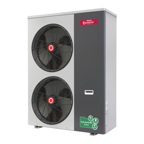
MODEL ILAHP
INVERTER EXTREME
LOW AMBIENT
AIR-TO-WATER
HEAT PUMP
INSTALLATION AND
OPERATION MANUAL
SECTION 1: INTRODUCTION ..........................................
Hazard Definitions
Benefits and Features
Specifications
Performance
Typical System Diagram
SECTION 2: INSTALLATION ............................................
Choose The Correct Heat Pump
Installation Location
Water Loop Connection
Electrical Connections
Control Input Connections
Control Output Connections
Dimensions
Required Clearances
IN UNITED STATES: 260 NORTH ELM ST. WESTFIELD, MA 01085 800-465-8558 / FAX (413) 564-5815
IN CANADA: 7555 TRANMERE DRIVE, MISSISSAUGA, ONTARIO, L5S 1L4 (905) 670-5888 / FAX (905) 670-5782
SECTION 3: GLYCOL/WATER SYSTEM .........................
2
SECTION 4: WIRING ........................................................
Control Wiring Connection
Wiring Diagrams & Definitions
SECTION 5: REMOTE TOUCHSCREEN DISPLAY ........
Overview of Remote Touch Screen
6
Electrical System Diagram
Display Windows and Functions
SECTION 6: PARAMETERS ............................................
SECTION 7: TROUBLESHOOTING .................................
SECTION 8: REPLACEMENT PARTS .............................
WARRANTY ......................................................................
ILHP2-0722
10
12
15
33
50
52
53
Warranty
Registration
Advertisement

Related Manuals for SpacePak Solstice ILAHP48


Summary of Contents for SpacePak Solstice ILAHP48
- Page 1 ILHP2-0722 MODEL ILAHP INVERTER EXTREME LOW AMBIENT AIR-TO-WATER HEAT PUMP INSTALLATION AND OPERATION MANUAL SECTION 1: INTRODUCTION .......... SECTION 3: GLYCOL/WATER SYSTEM ......Hazard Definitions SECTION 4: WIRING ............Benefits and Features Control Wiring Connection Specifications Wiring Diagrams & Definitions Performance SECTION 5: REMOTE TOUCHSCREEN DISPLAY ..
- Page 2 ILAHP Inverter Extreme Air-to-Water Heat Pump SECTION 1: INTRODUCTION Benefits and Features Inverter Compressor Read Before Proceeding ILAHP Inverter Extreme Heat Pump uses Inverter technology to precisely match the heating or cooling load. Hazard Definitions Advanced Controls Unit function is managed by a parametric microprocessor allowing The following terms are used throughout this manual to bring on site adjustment to match specific operating requirements.
- Page 3 ILAHP Inverter Extreme Air-to-Water Heat Pump Specification Units ILAHP48 Capacity Range BTU/hr 24,226-63,466 Efficiency Range 7.26-10.41 Cooling Efficiency IPLV 18.4 Delivered Water Temp Range DegF 42-77 Ambient Temp Range DegF 5-109 Capacity Range BTU/hr 15,354-63,807 Efficiency Range 1.64-5.41 Heating Delivered Water Temp Range DegF 59-130 Ambient Temp Range...
- Page 4 ILAHP Inverter Extreme Air-to-Water Heat Pump ILAHP Heating Performance (all data based on pure water and rated flow) 113° Leaving Water Temperature, Hea ng 95°F Leaving Water Temperature, Hea ng Maximum Capacity Maximum Capacity 70000 70000 Minimum Capacity Minimum Capacity COP @ Maximum Capacity COP @ Maximum Capacity 60000...
- Page 5 Heat Pump Installation with Domestic Hot Water Offset *Autofill system is suggested but not required by SpacePak. If such installation is desired or required by local code, the Autofill MUST draw from a reservoir of pre-mixed glycol/water solution. Filling directly from a well or municipal water source may introduce contaminants and will dilute the glycol solution in the event of a system leak.
- Page 6 ILAHP Inverter Extreme Air-to-Water Heat Pump SECTION 2: INSTALLATION Choose the Correct Heat Pump Electrical Connections Perform appropriate load calculation to determine required ILAHP Heat Pump must be connected to an individual 230V heating or cooling load for the project. Refer to specifications in (220V-240V) circuit, sized and protected according to the this manual to determine proper size heat pump.
- Page 7 Communication Connections RS485 connections SpacePak air handler panel. provided for two-way serial communication via Modbus protocol If the circuit is turned on remotely, it must still have the ability to to external Building Management and Monitoring equipment. operate for the unit's freeze protection or the warranty will be void.
- Page 8 ILAHP Inverter Extreme Air-to-Water Heat Pump Dimensions Unit Dimensions (inch (mm)) ILAHP Top View Front View Side View ILAHP – 8 –...
- Page 9 ILAHP Inverter Extreme Air-to-Water Heat Pump Required Clearances Unit shall be mounted per local codes and high enough off ground to allow for proper condensate drainage – 9 –...
- Page 10 SECTION 3: GLYCOL/WATER SYSTEM Table 1 ILAHP Glycol Concentrations (10% Minimum, 50% Maximum) Ethylene Glycol % Min. Ambient Temp for Operation 23°F/-5°C 14°F/-10°C 2°F/-17°C -13°F/-25°C -36°F/-38°C SpacePak Capacity Multiplier 0.98 0.96 0.93 0.91 0.89 Pressure Drop Multiplier (Cooling) 1.06 1.12 1.16 1.25...
- Page 11 ILAHP Inverter Extreme Air-to-Water Heat Pump Glycol/Water System Design System Volume and Expansion Volume The ILAHP has a recommended flow that should be maintained To ensure smooth temperature control and minimize cycling of refrigeration system, all installations must have total circulating during all operation.
- Page 12 ILAHP Inverter Extreme Air-to-Water Heat Pump SECTION 4: WIRING ILAHP Control Wiring Connection The SpacePak ILAHP requires a dry contact (relay) signal to enable and select between heating and cooling modes. They will not operate on the 24V signals from typical thermostats or air handlers.
- Page 13 ILAHP Inverter Extreme Air-to-Water Heat Pump Wiring Diagrams and Definitions: Internal Wiring CAUTION: The remote On/Off, Remote Heat/Cool, Heat/Cool On/Off, and DHW Enable inputs are for voltage-free relay contacts only. Any voltage introduced to the controls at these points will immediately destroy the primary unit control.
- Page 14 ILAHP Inverter Extreme Air-to-Water Heat Pump Wiring Diagrams and Definitions: Field Connections AUX Heat Overtemp Switch CAUTION: The remote On/Off, Remote Heat/Cool, Heat/Cool *When any auxiliary heating device, regardless of the source, is On/Off, and DHW Enableinputs employed and controlled by the heat pump, a Normally Closed are for voltage-free relay thermal switch or fuse must be wired between AI/DI 15 &...
- Page 15 ILAHP Inverter Extreme Air-to-Water Heat Pump SECTION 5: REMOTE TOUCHSCREEN DISPLAY Overview of the Remote Touchscreen Remote Display Connection Diagram Display ILAHP The remote touchscreen display is the Operation and Service Heat interface to the ILAHP control. Pump The full-color screen displays current water inlet and outlet temperatures, outdoor ambient temperature, and DHW tank temperature (if this feature is enabled).
- Page 16 ILAHP Inverter Extreme Air-to-Water Heat Pump Main Display Window Defrosting Icon Local Time Fault indicated. Touch to See Fault Log. Operating Mode Inlet Water Temp DHW Tank Temp Outlet Water Temp Power Button. Setting Key Operating, Red. Standby, White. Timer On/Off Key, Mode Key Target Temp Set Lock...
- Page 17 ILAHP Inverter Extreme Air-to-Water Heat Pump Mode Selection and Target Temperature Setting Mode Selection On main display window, press ‘M’ button, it will show five modes. After having chosen one mode, It will return to main display automatically. When choosing Hot Water mode, the display will show 'hot water' When choosing Heating mode, the display will show ‘heating’...
- Page 18 ILAHP Inverter Extreme Air-to-Water Heat Pump Target Temp Set Screen This can be adjusted by pressing the temp (on the screen) which opens a new screen and then entering in a numeric value within specified parameters in the control (see parameter chart for min and max settings). Once a target is set, the user will need to press “enter”...
- Page 19 ILAHP Inverter Extreme Air-to-Water Heat Pump Timer Key The timer key allows the user to set a schedule to not allow the unit to operate through timers regardless of set points. Timer Key Screen The user can use the day schedule on the bottom row to select the day they want to set the unit to be off. Once the day is selected, the user will need to select the appropriate times (AM or PM) that the unit will not need to be run.
- Page 20 ILAHP Inverter Extreme Air-to-Water Heat Pump Settings Screen Settings > Status Under the status menu, the user can view the following status’ of the unit during real time operation Unit Status (on/off). Whether the unit is operating or not Present Mode: Displays the mode that the unit is running in (heating, cooling etc..) Inlet Water Temp: Displays the current inlet water temperature being measured Outlet Water Temp: Displays the current outlet water temperature being measured Tank Water Temp: Displays the domestic hot water tank temperature, if used.
- Page 21 ILAHP Inverter Extreme Air-to-Water Heat Pump Settings > Electric Heating All ILAHP units have a feature that allows the unit to turn on a dry contract “AUX” relay (see wiring section) for an external electric heater. The heater can be controlled by selecting and adjusting the appropriate parameters (see parameter chart) to provide supplemental heat when desired.
- Page 22 ILAHP Inverter Extreme Air-to-Water Heat Pump Settings > Whisper Mode The purpose of the Whisper Key is to silence the fans and unit for a quieter operation. When pressing the Whisper key, the user has two options. “Fast Whisper” or “Whisper Timer”. Fast Whisper- To enable the "Fast Whisper"...
- Page 23 ILAHP Inverter Extreme Air-to-Water Heat Pump Settings > Curve The curve key allows a user to visually see (in real time and historical) the operational curves of the inlet water, outlet water and ambient on graph of temperature versus time period. Settings >...
- Page 24 ILAHP Inverter Extreme Air-to-Water Heat Pump Settings > Factory > Passcode ‘’22’’ Password = “22” the following menus appear: Settings > Factory > Passcode ‘’22’’ > Parameters Parameters Submenu Press this key to access certain parameters only meant to be changed by a user. Use the parameter chart from this manual to determine what parameters are accessible with the proper password.
- Page 25 ILAHP Inverter Extreme Air-to-Water Heat Pump Temperature Compensation/Outdoor Reset Screen The Outdoor Reset feature allows the Heat Pump to target specific Heating Temperatures according to the outdoor ambient temperature. The Outdoor Reset curve is determined by three values; The Maximum supply temperature, Parameter R42 The Offset, which is the Theoretical Target Temperature at 0°F Ambient The Slope, which is the change in Water Temp, with respect to the change in Ambient Temp.
- Page 26 ILAHP Inverter Extreme Air-to-Water Heat Pump Settings > Factory > Passcode ‘’22’’ > Unit State Unit State Submenu – 26 –...
- Page 27 ILAHP Inverter Extreme Air-to-Water Heat Pump Allows the user to see the current state of certain items. By selecting the appropriate top menu, the user can see how the unit is currently operating. See below chart for each item a user can monitor. Unit State Menu Possible Number Name...
- Page 28 ILAHP Inverter Extreme Air-to-Water Heat Pump Settings > Factory > Passcode ‘’22’’ > Failure Failure Log Submenu Press this key to find the log of the most recent faults the unit has encountered. The fault, the time of the fault and the date of the fault will all be recorded and displayed.
- Page 29 ILAHP Inverter Extreme Air-to-Water Heat Pump Settings > Factory > Passcode ‘’22’’ > Brightness Brightness Submenu The brightness key allows the user to adjust the screen brightness. Press the brightness bar to the right to make the display brighter and the left on the brightness bar to make the display less bright. Settings >...
- Page 30 ILAHP Inverter Extreme Air-to-Water Heat Pump – 30 –...
- Page 31 ILAHP Inverter Extreme Air-to-Water Heat Pump – 31 –...
- Page 32 ILAHP Inverter Extreme Air-to-Water Heat Pump – 32 –...
- Page 33 ILAHP Inverter Extreme Air-to-Water Heat Pump SECTION 6: PARAMETERS Factory Top Menu Number Name Range Description Default The control will retain the last operating mode when powered down Auto Start Yes/No and restarted System Quantity Not used on this unit. 4-Way Valve Polarity Not used on this unit.
- Page 34 ILAHP Inverter Extreme Air-to-Water Heat Pump Factory Top Menu Number Name Range Description Default Fan Motor Type High/Double/DC F01=DC fan The fan will run at the maximum speed according to F25 when the Max Cool Coil Temp 5-140°F Coil temperature is above F02 in Cooling Cooling High Speed Pressure Not used on this unit.
- Page 35 ILAHP Inverter Extreme Air-to-Water Heat Pump Factory Top Menu Number Name Range Description Default EEV1 EEV Adjust Mode Manual/Auto Auto E01 = Auto EEV is automatically controlled EEV1 Target Superheat Degree -36-36 Target suction superheat of EEV in Heating mode EEV1 EEV Initial Steps 0-500 Initial EEV opening at startup in Heating...
- Page 36 ILAHP Inverter Extreme Air-to-Water Heat Pump Factory Top Menu Number Name Range Description Default R01 = Ordinary, Pump runs whenever Remote On/Off is closed. Ordinary/Special/ R01 = Special, Pump runs when when Remote On/Off and Heat/ Running Mode Special Interval Cool On/Off is closed.
- Page 37 ILAHP Inverter Extreme Air-to-Water Heat Pump Meaning of Each Parameter Parameter A (Protection Parameter) Anti-Freeze Protection Detect Malfunction Cooling mode: After the compressor starts, it will detect water outlet temperature (T02). If T02≤A01 or the suction pressure is lower than A02 for 10s, the unit will enter anti-freezing protection. Note: After the compressor has run for 5min, the unit starts to detect its suction pressure.
- Page 38 ILAHP Inverter Extreme Air-to-Water Heat Pump Parameter D (Defrost Parameter) Requirements to enter defrosting ① Check the suction pressure for 1 min. after the compressor starts, and when suction pressure is ≤D05, defrosting timing shall be started. ② If the suction pressure sensor failure, the unit will start timing defrost, and the defrost cycle is D03, defrost time is D04. Requirements to stop defrosting ① After starting defrosting, when T09≥D02,and T06≥D01, the unit stops defrosting;...
- Page 39 ILAHP Inverter Extreme Air-to-Water Heat Pump Parameter F (Fan Parameter) Normally, in heating mode or cooling mode, fan will start up 10s ahead of compressor and 30s later to shut off. Fast mute function When the fast mute function is turned on, the fan will run according to the parameter F13 if it needs to be turned on, and exit the mute function after 8 hours.
- Page 40 ILAHP Inverter Extreme Air-to-Water Heat Pump Parameter H (System Parameter) Parameter P (Pump Parameter) In normal modes of cooling, heating and electrical heating, the water pump will be started at least P04 time earlier and shut down 2 minutes later than the compressor. The water pump shall be started all the time during defrosting. The controller starts to inspect water flow switch after P04-10s.
- Page 41 ILAHP Inverter Extreme Air-to-Water Heat Pump Parameter R (Temperature Parameter) When the mode is hot water mode and tank temperature<R01-R04, the unit is running in hot water mode and the target temperature is R01. When water tank temperature≥R01+R05, the unit will exit hot water mode. The unit use the hot water side to defrost when in defrosting.
- Page 42 ILAHP Inverter Extreme Air-to-Water Heat Pump Modbus RTU Protocol 1. Transmission Format Baud Rate 9600bps Start bit Byte width Parity Stop bits Slave address 2. Packet Format Address Function Data CRC checksum 16bits 03:Function of reading multi registers 16bits N*16bits 16bits 16:Function of presenting multi registers 06: Fuction of presenting single...
- Page 43 ILAHP Inverter Extreme Air-to-Water Heat Pump Address Function Number Content mode Default Description Remark 1-Electric heater stage 1 1032 03/16 Electric heater energy stage read/write 2-Electric heater stage 2 DIGI1 3-Electric heater stage 3 1033 03/16 3-way valve polarity read/write 0-ON on hot water mode/1-OFF on hot water mode DIGI1 1034...
- Page 44 ILAHP Inverter Extreme Air-to-Water Heat Pump Address Function Number Content mode Default Description Remark 1086 03/16 Timer mute read/write 0-no/1-yes DIGI1 1087 03/16 Manual-control Fan Speed read/write 0-no/1-yes DIGI1 1088 03/16 Reserved read/write 1089 03/16 DC fan rated speed read/write 600r 300~1300 DIGI1...
- Page 45 ILAHP Inverter Extreme Air-to-Water Heat Pump Address Function Number Content mode Default Description Remark 1158 03/16 Heating target temp read/write R10~R11 TEMP1 1159 03/16 Cooling target temp read/write R08~R09 TEMP1 1160 03/16 Heating restart difference read/write 0~10°C TEMP1 Heating constant temp downtime 1161 03/16 read/write...
- Page 46 ILAHP Inverter Extreme Air-to-Water Heat Pump Address Function Number Content mode Default Description Remark 1228 03/16 Max water heating temp. read/write 20~60°C TEMP1 Max water heating temp.(Under Low 1229 03/16 read/write 20~60°C TEMP1 Temp.) Max Water heating temp.(Under High 1230 03/16 read/write 20~60°C...
- Page 47 ILAHP Inverter Extreme Air-to-Water Heat Pump Address Function Number Content mode Default Description Remark bit0:O01 compressor output (0-OFF/1-ON) bit1:Reserved bit2:O03 fan high speed output (0-OFF/1-ON) bit3:O04 fan low speed output (0-OFF/1-ON) bit4:O05 water pump output (0-OFF/1-ON) bit5:O06 hot water pump output (0-OFF/1-ON) bit6:O07 4 way valve 1 (0-OFF/1-ON) bit7:O08 Electric heater stage 1 (0-OFF/1-ON) bit8:O09 Electric heater stage 2 (0-OFF/1-ON)
- Page 48 ILAHP Inverter Extreme Air-to-Water Heat Pump Address Function Number Content mode Default Description Remark 2054 Reserved read TEMP1 2055 Anti-freeze temp read real test value TEMP1 2056 Reserved read TEMP1 2057 AC input currents read real test value DIGI5 2058 Room temp read real test value...
- Page 49 ILAHP Inverter Extreme Air-to-Water Heat Pump Address Function Number Content mode Default Description Remark bit0: Voltage electromechanical current down frequency alarm bit1: Compressor weak magnetic protection alarm bit2: Power unit overheating alarm bit3: Reserved bit4: AC input current down alarm bit5: EEPROM failure warning bit6: Reserved 2083...
- Page 50 ILAHP Inverter Extreme Air-to-Water Heat Pump Address Function Number Content mode Default Description Remark bit0:Discharge over heat protection 3 times (0-no/1- yes) bit1:Reserved bit2:Reserved bit3:Reserved bit4:Outlet water overtemp protection 3 times (0-no/1-yes) bit5:Reserved bit6:Reserved 2088 Failure 4 read DIGI1 bit7:Reserved bit8:Reserved bit9:Reserved bit10:Reserved...
- Page 51 ILAHP Inverter Extreme Air-to-Water Heat Pump SECTION 7: TROUBLESHOOTING ILAHP Error Codes Error Description Cause Solution Code Inlet Water Temp Sensor Sensor failed open or shorted. Wiring fault Correct wiring or replace 5k sensor T1 Outlet Water Temp Sensor Sensor failed open or shorted. Wiring fault Correct wiring or replace 5k sensor T2 Correct wiring or replace 5k sensor (optional P032 DHW Water Temp Sensor...
- Page 52 ILAHP Inverter Extreme Air-to-Water Heat Pump Exploded Diagram SECTION 8: REPLACEMENT PARTS P18 (13130031) Explosion 36 44 diagram complete machine structure 48 49 Explosion diagram electrical structure – 52 –...
- Page 53 ILAHP Inverter Extreme Air-to-Water Heat Pump Replacement Parts Part Number Description 45W05-WG1371-01 Oval Grommet 45W41-WG1372-01 Rear Compressor Access Panel 45W11-WG1211-01 Flow Switch 45W40-WG1373-01 Water Outlet Manifold 45W50-WG1374-01 Refrigerant to Water Heat Exchanger 45W41-WG1375-01 Heat Exchanger Support 45W05-WG1376-01 Wiring Access Split Bushing 45W41-WG1377-01 Compressor End Panel 45W41-WG1378-01...
- Page 54 (4) below). If any parts should prove defective due to improper workmanship and/or material for a period of two (2) years from the date of installation, SpacePak will replace any defective part without charge for that part. Replacement parts are warranted for the remainder of the original 2-year warranty period. Parts used as replacement may be of like kind and quality and may be new or remanufactured.
- Page 55 The following items apply to each Limited Warranty offered by SpacePak. 4) NO LABOR. Each Limited Warranty offered by SpacePak does NOT include labor or any other costs incurred for service, maintenance, repair, removing, replacing, installing, complying with local building and electric codes, shipping or handling, or replacement of the System/Products, compressors or any other parts.
- Page 56 IN UNITED STATES: 260 NORTH ELM ST. WESTFIELD, MA 01085 800-465-8558 / FAX (413) 564-5815 IN CANADA: 7555 TRANMERE DRIVE, MISSISSAUGA, ONTARIO, L5S 1L4 (905) 670-5888 / FAX (905) 670-5782...
Need help?
Do you have a question about the Solstice ILAHP48 and is the answer not in the manual?
Questions and answers