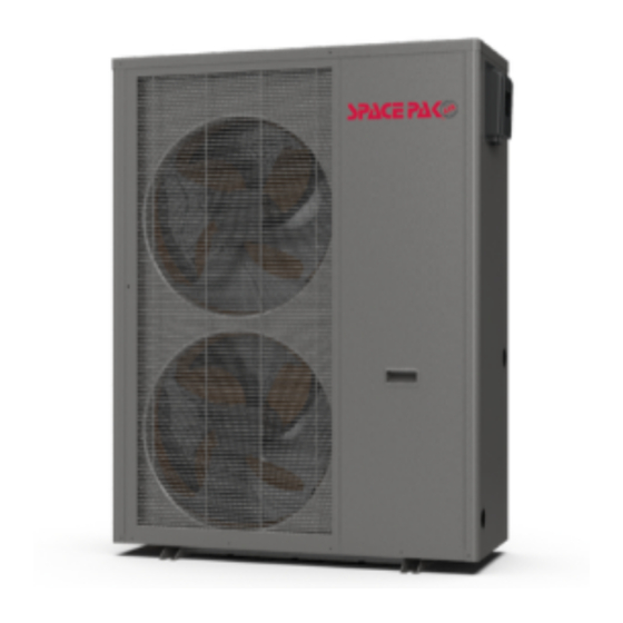
SpacePak SIM-036 Installation Manual

SpacePak SIM-036 Installation Manual

Inverter air-to-water heat pump

Advertisement

INVERTER
AIR-TO-WATER
HEAT PUMP
INSTALLATION
MANUAL
SECTION 1: PREFACE .....................................................
SECTION 2: HAZARD DEFINITIONS ..............................
Warning .....................................................................................
Attention ....................................................................................
SECTION 3: UNIT SPECIFICATION ................................
Air Flow Direction ......................................................................
Dimensions ...............................................................................
Specification Data .....................................................................
Typical Piping ............................................................................
SECTION 4: INSTALLATION ............................................
Choosing the Heat Pump ..........................................................
Install Location/Clearances ......................................................
Install Method ............................................................................
Provisions for Glycol ................................................................. 7 & 8
Low Ambient Features ..............................................................
Pressure Test ............................................................................
IN UNITED STATES: 260 NORTH ELM ST. WESTFIELD, MA 01085 800-465-8558 / FAX (413) 564-5815
IN CANADA: 7555 TRANMERE DRIVE, MISSISSAUGA, ONTARIO, L5S 1L4 (905) 670-5888 / FAX (905) 670-5782
SECTION 5: WIRE CONTROLLER ..................................
2
Controller Details ...................................................................... 9-28
2
SECTION 6: WIRING AND DEFINITIONS .......................
2
2
Board Layout. ............................................................................ 29-32
I/O Definitions. .......................................................................... 32-36
3
Parameter Definitions. .............................................................. 37-41
3
4
5
5
6
6
6
6
8
8
IAW2-0620
9
29

Advertisement

Table of Contents
loading
Need help?

Need help?

Do you have a question about the SIM-036 and is the answer not in the manual?

Questions and answers

Subscribe to Our Youtube Channel

Summary of Contents for SpacePak SIM-036

  • Page 1: Table Of Contents

    IAW2-0620 INVERTER AIR-TO-WATER HEAT PUMP INSTALLATION MANUAL SECTION 1: PREFACE ............. SECTION 5: WIRE CONTROLLER ........Controller Details ..............9-28 SECTION 2: HAZARD DEFINITIONS ......SECTION 6: WIRING AND DEFINITIONS ....... Warning ..................Attention ..................Board Layout................29-32 I/O Definitions................32-36 SECTION 3: UNIT SPECIFICATION ........
  • Page 2: Section 1: Preface

    Inverter Air-to-Water Heat Pump Section 1: Read Before Proceeding Section 2: Hazard Definitions ■ In order to provide the customers with high quality, strong The following terms are used throughout this manual to bring reliability and good versatility a product, this heat pump is attention to the presence of potential hazards or to important produced by strict design and manufacturing standards.
  • Page 3: Section 3: Unit Specification

    Inverter Air-to-Water Heat Pump Section 3: Unit Specification SIM-036 Remote control ( eld installed) Horizontal air outlet Max wired remote control distance is 600ft Water Out Water In SIM-060 Remote control ( eld installed) Horizontal air outlets Max wired remote control distance is 600ft...
  • Page 4: Dimensions

    Inverter Air-to-Water Heat Pump Specification Unit Dimensions (inch) SIM-036 SIM-060 – 4 –...
  • Page 5: Specification Data

    Inverter Air-to-Water Heat Pump Specification Model SIM-036 SIM-060 Max Heating Capacity* (90hz) BTU/h 39240 56300 Min Heating Capacity* (30hz) BTU/h 11950 21986 Max Cooling Capacity** (90hz) BTU/h 34121 49476 Min Cooling Capacity** (30hz) BTU/h 11341 16445 COP * Up to 5.01 Up to 4.67...
  • Page 6: Section 4: Installation

    Inverter Air-to-Water Heat Pump Section 4: Installation Choose a Right Heat Pump Unit Electrical Connections Perform appropriate load calculation to determine required • The power supply must go through the wire access and be heating or cooling load for the project. Refer to specifications in connected to the power supply terminals in the control box.
  • Page 7: Provisions For Glycol

    2" recommended flow is 13GPM at which the head loss is 25ft W.C, 11PSI or 73kPa. For the SIM-036 the recommended water flow is 7GPM at which the head loss is 6 ft W.C. or 6 P.S.I. These head loss values are based upon pure water, see Figure 1 for multipliers to correct for various concentrations of anti-freeze solution.
  • Page 8: Low Ambient Features

    If the pump load exceeds this, provide a separate power source to Obtain all components specified in the Typical System Diagram. the pump. DO NOT feed power to the pump from the SpacePak air Make sure all components and piping comply with applicable handler panel.
  • Page 9: Section 5: Wire Controller

    Inverter Air-to-Water Heat Pump Section 5: Wire Controller Overview of Wire Controller Electrical System Diagram The wire controller records the inlet temp and outlet temp System Diagram every five minutes and displays through a curve graph. The record can be saved for a maximum period of 2 months. Color screen Heat pump The slave address on RS-485 communication can be altered...
  • Page 10 Inverter Air-to-Water Heat Pump Main Display Window 95°F 131°F 110°F Heating Contents and Buttons on Main Display Window On the startup interface, contents and buttons on main display are illustrated above. Animation on Main Display Window When the unit is in defrosting mode, the defrosting icon will show until the defrosting is completed. When the unit is shutdown, the main display will turn grey as illustrated below.
  • Page 11 Inverter Air-to-Water Heat Pump Mode Selection and Target Temperature Setting Mode Selection On main display window, press ‘M’ button, it will show five modes. After having chosen one mode, It will return to main display automatically. When choosing Heating mode, the display will show ‘heating’ When choosing Cooling mode, the display will show ‘cooling’...
  • Page 12 Inverter Air-to-Water Heat Pump Fast Heating Display Window 100°F 110°F On the main interface, press fast heating key, it will display the pop-ups window of electric heater on and off. Key Operation Method When touching the area except pop-ups window, it will return to main display window. Press , the fast heating function will be activated,at the same time automatically return to the main display window.
  • Page 13 Inverter Air-to-Water Heat Pump Time Power On and Off Setting Display The function of parameter preservation and timing are operated by controller. The wire controller can only display and set the timing time. No matter when it starts or terminates functioning, the timing power on and off key on the main display remains green. When it does not conducting this function, it will be white.
  • Page 14 Inverter Air-to-Water Heat Pump Only Use ‘Off’ Timer When using only off timer, the ‘Off’ button will be lightened as illustrated above. The unit will power off once at the according ‘Hour’and ‘Min’ and no more shutdown will be conducted at other timing. Under this status, other operation on the display should follow ‘Timer Full Closed’.
  • Page 15 Inverter Air-to-Water Heat Pump Setting Display Window Factory Return parameter Status of current running parameter Temperature System curve time Mute function means function off, means function on) – 15 –...
  • Page 16 Inverter Air-to-Water Heat Pump Press ‘Operation Mode’ in the above illustration to check the current running parameter. Press ‘Factory’ in the above illustration and enter the correct code to enter the factory parameter setting interface or the unit status parameter interface. Press ‘Clock’...
  • Page 17 Inverter Air-to-Water Heat Pump Running Mode Press the running mode button in the setting interface to check the current operation mode and the main temperature status as shown below. Heating 113°F 113°F 113°F 51°F Clock Setting Display Press ‘Clock’ button to enter the system clock setting interface as below. Return Press up key and increase...
  • Page 18 Inverter Air-to-Water Heat Pump Setting Display of Mute Timer Press the Mute button on the setting interface to enter the fast mute and mute timer setting interface as shown below. Fast Mute When the unit is under mute status, the mute setting button will appear as mute icon and the pop-ups window will show non-mute icon When the unit is under non-mute status, the mute setting button will appear as non-mute icon...
  • Page 19 Inverter Air-to-Water Heat Pump Time Mute Return On/off key to choose whether to start mute timer Time mute Time mute hour start min end Time mute Time mute min start hour end On/off key to choose whether to start mute timer function When under the mute timer mode, the button of ‘Mute timer’...
  • Page 20 Inverter Air-to-Water Heat Pump When the mute timer is closed, the button of ‘Mute Timer’ will turn grey and will show ‘Off’. All the time setting area will turn grey, meaning that the mute timer are not activated and the timer can not be set. Clean key return Current...
  • Page 21 Inverter Air-to-Water Heat Pump Curve Display Press ‘Curve’ button to switch to ‘Inlet and Outlet Curve’ interface. Degrees Fahrenheit Curve The curve function is provided to record the inlet and outlet temperature. The temperature data will be recorded every 5min, 12 sets of temperature data that collected will be saved every 1 hour. If the unit shutdown during one recording cycle resulting in an incomplete data (less than 12 sets of record point in 1 hour), then the record of this cycle will not be saved.
  • Page 22 Inverter Air-to-Water Heat Pump Customer Display Press ‘Factory’ button, input password ‘022’ or ‘22’ and press ‘enter’ to reach the customer Display. Return Check states Customer parameter History errors record Brightness of screen Status Interface Pressing “Unit State” will bring the user into the status of certain components. The top banner will display “Load Status”, “Switch Status”, and “Temp Status”.
  • Page 23 Inverter Air-to-Water Heat Pump System Parameter Display Check the Check the Check the Check the Check the defrosting next page protection parameters parameters parameters parameters parameters Check the System parameters Return Down key Up key Parameter s setting Press ‘Factory’ on the setting interface, input password ‘066’ or ‘66’ on the keyboard then press ‘enter’ to access the system parameter interface.
  • Page 24 Inverter Air-to-Water Heat Pump Return Return System Parameter Upload Press ‘YES’ on the display to start the system parameter uploading. During the operation, the control display will read ‘Uploading…’ in a red frame and all the buttons and functions will be disabled until the upload is completed. If the upload is succeed, the display will read ‘Succeed’...
  • Page 25 Inverter Air-to-Water Heat Pump Parameter Download The operation and the displays are the same as ‘System parameter Upload’. – 25 –...
  • Page 26 Inverter Air-to-Water Heat Pump Return Return Failure Interface Error Error Return Malfuncti Malfuncti Error code Error code Error on current on current time time Error code Malfuncti Error Error on current time Error Page up Page up Page up Page Page Page When failure occurs, press the ‘Failure’...
  • Page 27 Inverter Air-to-Water Heat Pump The operation process are as below. Entering screen inspection display Screen inspection display (Shown every time when entering) Touch control inspection pictures (Inspection on the corresponding area) – 27 –...
  • Page 28 Inverter Air-to-Water Heat Pump Brightness Control Press the ‘Brightness’ button to enter the screen brightness control display. Dragging or clicking the stripe in the middle to adjust the brightness of the screen. The brightness control is provided with power-off memory function. Press ‘Return’ to return to the last operation page.
  • Page 29: Section 6: Wiring And Definitions

    Inverter Air-to-Water Heat Pump Section 6: Wiring Diagrams & Definitions – 29 –...
  • Page 30 Inverter Air-to-Water Heat Pump Wiring Diagrams and Definitions CAUTION: The Remote On/ Off and Remote Heat/Cool inputs are for voltage-free relay contacts only. Any voltage introduced to the controls at these points will immediately destroy the primary unit control. – 30 –...
  • Page 31 Inverter Air-to-Water Heat Pump Wiring Diagrams and Definitions (continued) CAUTION: The Remote On/ Off and Remote Heat/Cool inputs are for voltage-free relay contacts only. Any voltage introduced to the controls at these points will immediately destroy the primary unit control. –...
  • Page 32: I/O Definitions

    Inverter Air-to-Water Heat Pump Wiring Diagrams and Definitions No. Main Board Instruction No. Main Board Instruction Power Null Wire DI 01 High Voltage Switch Input Power Live Wire DI 02 Low Voltage Switch Input RO 01 Not Used DI 03 Flow Switch Input RO 02 Pump...
  • Page 33 Inverter Air-to-Water Heat Pump Application of Each Input and Output Interface Interface Name Terminal No. Function Compressor RO01 Control inverter compressor , single-phase AC output (5A/250VAC). Circulating water pump RO02 Control circulating pump single-phase AC output (5A/250VAC). Control the four-way change valve, single-phase AC output Four-way valve RO03 (5A/250VAC).
  • Page 34 (24hr clock) Max fan speed in Mute Mode Speed 300-1300rpm 300-1300rpm 1071 600rpm Factory Quiet Mode High Number of DC Single Fan 1 SIM-036 Fan Motor Type 0 to 2 1073 Factory condenser fans 2 SIM-060 Single Fan – 34 –...
  • Page 35 Inverter Air-to-Water Heat Pump Parameter List (continued) Modbus Parameters Meaning Explanation Range SI Range Imp. Factory Setting Level Notes address System Control Parameters Auto start 0-ON/1-YES 1018 Factory 0=Controlled 0-Master/1- by Touchpad, Master/Slave Unit External Control 1019 Factory Slave 1=Controlled by Wired Connections Temperature Unit Temperature Units 0-˚C/1-˚F...
  • Page 36 Inverter Air-to-Water Heat Pump Parameter List (continued) Modbus Parameters Meaning Explanation Range SI Range Imp. Factory Setting Level Notes address Heater is delayed Delay of Electric Electric Heat Start by this time when 0-60min 1205 30min 30.0 Factory Heater Delay Ambient is above Heater starts Electric heater stat...
  • Page 37: Parameter Definitions

    Inverter Air-to-Water Heat Pump Meaning of Each Parameter Parameter A (Protection Parameter) A01——Anti-freezing setpoint of water outlet A02——Anti-freezing low pressure value A03——Anti-freezing protection difference Anti-Freeze Protection Detect Malfunction Cooling mode: After the compressor starts, it will detect water outlet temperature (T02). If T02≤A01 or the suction pressure is lower than A02 for 10s, the unit will enter anti-freezing protection.
  • Page 38 Inverter Air-to-Water Heat Pump Parameter D (Defrost Parameter) Requirements to enter defrosting ① Check the suction pressure for 1 min. after the compressor starts, and when suction pressure is ≤D05, defrosting timing shall be started. ② If the suction pressure sensor failure, the unit will start timing defrost, and the defrost cycle is D03, defrost time is D04. Requirements to stop defrosting ① After starting defrosting, when T09≥D02,and T06≥D01, the unit stops defrosting;...
  • Page 39 Inverter Air-to-Water Heat Pump Parameter F (Fan Parameter) Normally, in heating mode or cooling mode, fan will start up 10s ahead of compressor and 30s later to shut off. F01——Max speed in heating F02——Min speed in heating F03——LP of suction for heating at max speed F04——HP of suction for heating at min speed F05——Max speed in cooling F06——Min speed in cooling...
  • Page 40 Inverter Air-to-Water Heat Pump Parameter H (System Parameter) H01——Auto Start (Yes/NO) When H01 = 0, the heat pump haven’t the auto restart function for regular ON-OFF. That is to say: Every time the heat pump is connected to electricity, it is in power OFF status. When H01 = 1, the heat pump has the auto restart function for regular ON-OFF.
  • Page 41 Inverter Air-to-Water Heat Pump Parameter R (Temperature Parameter) R01——Hot Water Setpoint When the mode is hot water mode and tank temperature<R01-R04, the unit is running in hot water mode and the target temperature is R01. When water tank temperature≥R01+R05, the unit will exit hot water mode. The unit use the hot water side to defrost when in defrosting.
  • Page 42 Inverter Air-to-Water Heat Pump SIM Error Codes Error Code Error Type Notes HP Protection No Alarm LP Protection Alarm Electric Overheat Protection No Alarm E032 Flow Switch Protection No Alarm Primary Anti-freeze Protection No Alarm Secondary Anti-freezing Protection Alarm P182 Exhaust Overtemp No Alarm HP Protection 3+...
  • Page 43 Inverter Air-to-Water Heat Pump SIM Error Codes (continued) Error Code Error Type Notes AC Input Overload Alarm Input voltage Sample Fault Alarm Communication Failure between DSP and PFC Alarm Sensor Fault of Module/Radiator Alarm Communication Fault (DSP) Alarm "Communication Fault (Inverter Board) Alarm Overload Alarm Alarm...
  • Page 44 Inverter Air-to-Water Heat Pump Troubleshooting Chart Possible Cause Possible Solution – 44 –...
  • Page 45 Inverter Air-to-Water Heat Pump Troubleshooting (continued) Possible Causes for the Failure Possible Solutions – 45 –...
  • Page 46 Inverter Air-to-Water Heat Pump SIM Parts Order Code Description SIM-036 SIM-060 45W33-WG1194-01 Compressor 45W33-WG1259-01 45W41-WG1196-01 Access Panel 45W41-WG1196-02 45W19-WG1197-01 Access Panel Handle 45W43-WG1198-01 Fan Guard 45W43-WG1198-02 45W41-WG1199-01 Left Coil Guard 45W41-WG1199-02 45W34-WG1200-01 Fan Blade 45W31-WG1202-01 Fan Motor 45W41-WG1204-01 Rear Coil Guard...
  • Page 47 Inverter Air-to-Water Heat Pump – 47 –...
  • Page 48 IN UNITED STATES: 260 NORTH ELM ST. WESTFIELD, MA 01085 800-465-8558 / FAX (413) 564-5815 IN CANADA: 7555 TRANMERE DRIVE, MISSISSAUGA, ONTARIO, L5S 1L4 (905) 670-5888 / FAX (905) 670-5782...

This manual is also suitable for:

Sim-060

Table of Contents