
Subscribe to Our Youtube Channel
Related Manuals for Circutor RECmax-CVM 2-pole


Summary of Contents for Circutor RECmax-CVM 2-pole
- Page 1 Earth leakage circuit breaker with automatic reclosing and measurement system RECmax-CVM INSTRUCTION MANUAL (M175B01-03-22A)
- Page 2 RECmax-CVM Instruction Manual...
-
Page 3: Safety Precautions
CIRCUTOR, SA reserves the right to make modifications to the device or the unit specifications set out in this instruction manual without prior notice� CIRCUTOR, SA on its web site, supplies its customers with the latest versions of the device specifica- tions and the most updated manuals�... -
Page 4: Table Of Contents
3�2�3�- SAFETY SEAL ���������������������������������������������������������������������������������������������������������������������������������������������������11 3�3�- TERMINALS OF THE DEVICE ���������������������������������������������������������������������������������������������������������������������������������� 12 3�4�- CONNECTION DIAGRAMS ��������������������������������������������������������������������������������������������������������������������������������������� 14 3�4�1�- MEASUREMENT OF SINGLE-PHASE NETWORK: RECmax-CVM 2-POLE ������������������������������������������������������� 14 3�4�2�- MEASUREMENT OF THREE-PHASE NETWORK: RECmax-CVM 4-POLE �������������������������������������������������������� 15 3�5�- DISCONNECTION OF THE DEVICE �������������������������������������������������������������������������������������������������������������������������� 16 4�- OPERATION �������������������������������������������������������������������������������������������������������������������������������������������������������������������... - Page 5 RECmax-CVM 7�2�2� WRITE EXAMPLE: Function 0x05� ��������������������������������������������������������������������������������������������������������������������47 7�3�- MODBUS COMMANDS ��������������������������������������������������������������������������������������������������������������������������������������������48 7�3�1� MEASUREMENT VARIABLES �����������������������������������������������������������������������������������������������������������������������������48 7�3�2� ENERGY VARIABLES �����������������������������������������������������������������������������������������������������������������������������������������49 7�3�3� VOLTAGE AND CURRENT HARMONICS� ����������������������������������������������������������������������������������������������������������� 50 7�3�4� PROTECTION VARIABLES ���������������������������������������������������������������������������������������������������������������������������������� 51 7�3�5� DELETING PARAMETERS� ���������������������������������������������������������������������������������������������������������������������������������52 7�3�6� FUNCTION OF THE POSITIVE SAFE OUTPUT RELAY� ����������������������������������������������������������������������������������������52 7�3�7�...
-
Page 6: Revision Log
RECmax-CVM REVISION LOG Table 1: Revision log� Date Revision Description 10/17 M175B01-03-17A Initial Version Changes in the following sections: 11/17 M175B01-03-17B 7�3�2�- 7�3�11�5� Changes in the following sections: 12/17 M175B01-03-17C 3�3� - 4�7� - 4�9� - 4�10�1� - 4�10�2� Changes in the following sections: 04/18 M175B01-03-18A 3�3�... -
Page 7: 1�- Verifications Upon Reception
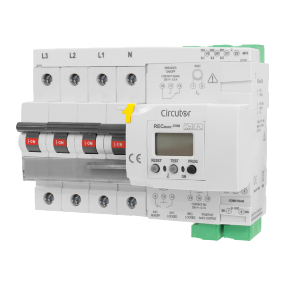
- An installation guide� - 1 MC3-75/0�25A measuring transformer - 1 WGC-30SC earth leakage transformer Immediately contact the carrier and/or CIRCUTOR's after-sales service if you detect any problem in the device upon reception� 2.- DESCRIPTION OF THE PRODUCT RECmax-CVM is a protection device, with cut-off capacity, which features overcurrent protection, ul- tra-immunised earth leakage protection and a power analyzer�... - Page 8 RECmax-CVM - 2 alarm outputs� - 1 output to indicate the status of the main switch� - 1 digital output� - RS-485 communications� Instruction Manual...
-
Page 9: 3�- Installing The Device
RECmax-CVM 3.- INSTALLING THE DEVICE 3�1�- PRELIMINARY RECOMMENDATIONS The operators using and handling the device must follow the safety measures estab- lished in the country where the device will be used to guarantee its safe operation, using personal protective equipment if needed� The RECmax-CVM device must be installed by authorised and qualified staff�... -
Page 10: 3�2�- Installation
RECmax-CVM 3�2�- INSTALLATION While the device is connected, the terminals, opening the cover or removing elements can expose parts that are hazardous to the touch� The device must not be used until the installation process is complete� The RECmax-CVM must be installed inside an electric panel or enclosure and mounted on a DIN rail 46277 (EN 50022)�... -
Page 11: 3�2�2�- Measurement Of The Phase Current
RECmax-CVM 3�2�2�- MEASUREMENT OF THE PHASE CURRENT The phase current must be measured using the MC1-75/0�25A (RECmax-CVM 2-pole) or MC3- 75/0�25A current transformer (RECmax-CVM 4-pole) supplied with the device� The MC transformer, supplied with a cable and 4-pole connector, must be connected to terminals 19,... -
Page 12: 3�3�- Terminals Of The Device
RECmax-CVM Warranty, Once the central part of the seal has been removed, the side section of the seal must remain attached� DO NOT REMOVE this part, it ensures that the insulated busbar at the top of the circuit breaker has not been removed or tampered with� The warranty of the device will be void if the safety seal has been tam- pered with or removed�... - Page 13 RECmax-CVM Figure 5:RECmax-CVM terminals, lower face� Instruction Manual...
-
Page 14: 3�4�- Connection Diagrams
I∆ (2) I∆ (1) Figure 6: Measurement of single-phase network: RECmax-CVM 2-pole� All active conductors that feed the load to be protected, including the neutral, must pass through the internal diameter of the earth leakage transformer� Do not pass the protective conductor or the earth wire�... -
Page 15: 3�4�2�- Measurement Of Three-Phase Network: Recmax-Cvm 4-Pole
RECmax-CVM 3�4�2�- MEASUREMENT OF THREE-PHASE NETWORK: RECmax-CVM 4-POLE Brown/Green C (22) Red/Blue IL3 (21) Green/White IL2 (20) Grey/Pink IL1 (19) I∆ (2) I∆ (1) Figure 7: Measurement of three-phase network: RECmax-CVM 4-poles� All active conductors that feed the load to be protected, including the neutral, must pass through the internal diameter of the earth leakage transformer�... -
Page 16: 3�5�- Disconnection Of The Device
RECmax-CVM 3�5�- DISCONNECTION OF THE DEVICE If after wiring the RECmax-CVM you decide to have the protected line disconnected, you must dis- connect the device manually by pushing the contact lever of the switch downwards and moving the mechanical lock (yellow sealable catch ) upwards�... -
Page 17: 4�- Operation
RECmax-CVM 4.- OPERATION 4�1�- OPERATING PRINCIPLE RECmax-CVM is a device for protecting single-phase or three-phase electrical installations of up to 63 A in which a high continuity of electrical service must be guaranteed� The device has an automatic reset system after a trip, so it reconnects on its own after a period of time, with the installation recovering power without human operator intervention�... -
Page 18: 4�2�- Description Of The Device
RECmax-CVM Table 4 (Cont�): Measurement parameters of the RECmax-CVM� Phases Total Parameter Units L1-L2-L3 Harmonic Breakdown - Voltage harm V (up to the 31st harmonic) Harmonic Breakdown - Current harm V (up to the 31st harmonic) Total Active Energy ... -
Page 19: 4�3�- Keyboard Functions
RECmax-CVM 4�3�- KEYBOARD FUNCTIONS The RECmax-CVM has 3 keys, Figure 11 Keyboard Figure 11: Keyboard� TEST, pressing this key causes a forced trip of the earth leakage protection� If the device has already tripped, pressing does not cause any action� Pressing the TEST key disables the automatic reclosing system, as it is consid- ered that the person who performs the local TEST will generate the reset for rearming the protection�... -
Page 20: 4�4�- Display
RECmax-CVM 4�4�- DISPLAY The device has a backlight display with green or red light, according to the status of the device� The backlight is green and in trip conditions it is red under normal operating conditions� PROG Figure 12: RECmax-CVM display� The device display shows different symbols that indicate the operating status of the device: The leakage symbol with the bars is activated when a leakage current is detected�... -
Page 21: 4�5�- Led Indicators
RECmax-CVM 4�5�- LED INDICATORS The device has 2 indicator LEDs, � Figure 13 LEDs Figure 13: RECmax-CVM LED indicators� Table 7: Description of the LEDs: Normal operating status� Normal operating status Description Permanent: Powered device� Green Flashing: Indicates that the value of the power supply > 265 V� Table 8: Description of the LEDs: Trip status�... -
Page 22: 4�6�- Inputs
RECmax-CVM 4�6�- INPUTS The RECmax-CVM has two keys: EXT ON/OFF input (terminals 9 and 10 in ) enables the remote control of the main Table 3 switch, trip or reset of the switch depending on its status� EXT LOCKED locking input (terminals 10 and 11 in ) allows you to disable the reset�... -
Page 23: 4�8�- Reset Lever And Manual Locking
RECmax-CVM Digital output (terminals 7 and 8 in ) can work as an alarm for the measurement Table 3 variables, to indicate that they are outside the programmed limits or to generate energy pulses, see “ ” 7.3.11.5. PROGRAMMING THE DIGITAL OUTPUT ... -
Page 24: 4�10�- Trip Status
RECmax-CVM 4�10�- TRIP STATUS The device may be tripped due to: Actuation of the protection due to an installation defect, whether the earth leakage protec- tion or protection against overloads or a short-circuit� Manual opening of the main switch, lowering the switch lever� ... -
Page 25: 4�10�2�- Automatic Reclosing Is Not Possible
RECmax-CVM PROG Figure 14: Screens after an earth leakage protection trip� If the trip is caused by a fault in the protection due to overloads or a short circuit, a screen will ap- pear indicating the number of reclosing attempts carried out by the circuit breaker� (See Figure 15 “5.2.2.- CIRCUIT BREAKER TRIP”... - Page 26 RECmax-CVM Table 15: Trip status: Automatic reclosing is not possible� Trip status: Automatic reclosing is not possible Main Reset lever Green LED Red LED switch Open Down Permanently on (Lever down) REC LOCKED POSITIVE SAFE BREAKER ON/OFF Display Alarm OUTPUT Alarm output Contact 16-17: closed Closed...
-
Page 27: 5�- Display
RECmax-CVM 5.- DISPLAY 5�1�- NORMAL OPERATING STATUS In the normal operating status, the device shows 5 information screens on the protection of the device and access to the electrical parameter display screens� Press the PROG key to move between the different screens� Table 16: Display screens: Normal operating status�... - Page 28 RECmax-CVM Table 16 (Cont�): Display screens: Normal operating status� Display screens: Normal operating status� Screen to access the communications settings parameters display� Hold down the PROG key (> 3s) to access the screens displaying the RS-485 communications settings parameters (“ 5.1.2.- COMMUNICATIONS SETTINGS PARAMETERS )�...
-
Page 29: 5�1�1�- Electrical Parameters Display Screens
RECmax-CVM 5�1�1�- ELECTRICAL PARAMETERS DISPLAY SCREENS shows the electrical parameters display menu� Figure 17 The electric parameters display screens are displayed for 30 seconds, after that time, the device switches to the Delay and Sensitivity screen� PROG > 3s RESET Voltage PROG RESET... - Page 30 RECmax-CVM 5�1�1�1�- VOLTAGE The device measures and displays the voltage of each of the lines, L1, L2 and L3 ( )� Figure 18 RESET PROG RESET RESET RESET RESET RESET RESET Figure 18: Voltage display menu� 5�1�1�2�- CURRENT The device measures and displays the current of each of the lines, L1, L2 and L3 ( )�...
- Page 31 RECmax-CVM 5�1�1�3�- ACTIVE POWER The device measures and displays the active power of each of the lines, L1, L2 and L3 ( )� Figure 20 RESET PROG RESET RESET RESET RESET RESET RESET Figure 20: Active Power display menu� 5�1�1�4�- INDUCTIVE REACTIVE POWER The device measures and displays the inductive reactive power of each of the lines, L1, L2 and L3 )�...
- Page 32 RECmax-CVM 5�1�1�5�- CAPACITIVE REACTIVE POWER The device measures and displays the capacitive reactive power of each of the lines, L1, L2 and L3 )� Figure 22 RESET PROG RESET RESET RESET RESET RESET RESET Figure 22: Capacitive reactive power display menu� 5�1�1�6�- APPARENT POWER The device measures and displays the Apparent power of each of the lines, L1, L2 and L3 ( )�...
- Page 33 RECmax-CVM 5�1�1�7�- COS φ The device measures and displays the of each of the lines, L1, L2 and L3 ( )� Cos φ Figure 24 RESET PROG RESET RESET RESET RESET RESET RESET φ Figure 24: cos display menu� 5�1�1�8�- THD VOLTAGE The device measures and displays the of each of the lines, L1, L2 and L3 ( )�...
-
Page 34: 5�1�2�- Communications Settings Parameters Display Screens
RECmax-CVM 5�1�1�9�- THD CURRENT The device measures and displays the of each of the lines, L1, L2 and L3 ( )� Figure 26 THD current RESET PROG RESET RESET RESET RESET RESET RESET Figure 26: THD(I) display menu� 5�1�2�- COMMUNICATIONS SETTINGS PARAMETERS DISPLAY SCREENS The RS-485 communications settings parameters are shown in �... -
Page 35: 5�2�- Trip Status
RECmax-CVM 5�2�- TRIP STATUS When the trip occurs the device shows the display screens in red� 5�2�1�- EARTH LEAKAGE PROTECTION TRIP Press the PROG key to move between the different screens� Table 17: Display screens: Earth leakage protection trip� Display screens: Earth leakage protection trip Delay and Sensitivity Value of the leakage current which caused the trip�... -
Page 36: 5�2�2�- Circuit Breaker Trip
RECmax-CVM 5�2�2�- CIRCUIT BREAKER TRIP Press the PROG key to move between the different screens� Table 18: Display screens: Circuit breaker trip� Display screens: Circuit breaker trip Delay and Sensitivity No� of trips which have occurred due to circuit breaker� Total no�... -
Page 37: 5�2�4�- Trip Due To Ext On/Off Input
RECmax-CVM 5�2�4�- TRIP DUE TO EXT ON/OFF INPUT When tripping the device with the EXT ON/OFF input, the device will display the normal operating , but instead of displaying the leakage current, it will display the screen in status screens, Table 16 Figure 29�... -
Page 38: 6�- Configuration
That is why it is very important that it is adjusted by a trained technician to decide on the most appropriate type of protection in each installation� CIRCUTOR accepts no responsibility for incorrect working of the device due to erroneous adjustment 6�1�- EARTH LEAKAGE PROTECTION... -
Page 39: 6�1�2�- Sensitivity Current, Iδn
RECmax-CVM When the value on the screen is the desired value, press the PROG key to jump to the next program- ming point� If you do not press any key for 10 s, the screen shown in appears and the device opens the Figure 31 Delay and Sensitivity screen, without saving the changes made�... -
Page 40: 6�2�- Automatic Reclosing
RECmax-CVM 6�2�- AUTOMATIC RECLOSING To configure the automatic reclosing parameters, press the PROG key for more than 3 seconds, while the Leakage current or Total no� of trips screen is displayed� PROG > 3s PROG PROG RESET RESET RESET PROG PROG RESET RESET... -
Page 41: 6�2�2�- Srm: Circuit Breaker Reclosing Sequence
RECmax-CVM Table 20 (Cont�): Available sequences (SDR)� SDR: Available sequences DI 6 30s, 1, 2, 3, 4, 8 and 16 min� 30 min� DI 7 1 min� 30 min� DI 8 90 s� 30 min� DI 9 2, 4 and 6 min� the rest 15 min�... -
Page 42: 6�2�3�- Rstc: Partial Meter Resetting
RECmax-CVM Press the PROG key to save the selected sequence and exit the setup menu; when exiting, the screen is displayed for a few seconds� Figure 32 If you do not press any key for 10 s, the screen shown in appears and the device opens the Figure 31 Delay and Sensitivity screen, without saving the changes made�... -
Page 43: 6�2�5�- Freq: Nominal Frequency
RECmax-CVM STD, the contactor of the REC LOCKED output acts without positive safety� POS, the contactor of the REC LOCKED output acts with positive safety� Press the PROG key to save the selected option and exit the setup menu; when exiting, the screen in is displayed for a few seconds�... -
Page 44: 6�2�6�- Fact: Factory Configuration
RECmax-CVM 6�2�6�- FACT: FACTORY CONFIGURATION The factory default Configuration can be restored on this screen� PROG PROG PROG Press the RESET key to move between the different options: NO, the factory values are not restored� YES, the factory values are restored� Selecting the option YES means a total reset, which includes the control parameters for the protection trigger�... -
Page 45: 6�4�- Locking The Configuration
RECmax-CVM 6�4�- LOCKING THE CONFIGURATION After configuring the device, you can lock the Configuration of the parameters� There are two locking methods: Physical locking, Program locking, 6�4�1�- PHYSICAL LOCKING The PROG key has a hole through which a sealing wire can be passed, so that it is physically impossible to press it�... -
Page 46: 7�- Rs-485 Communications
RECmax-CVM 7.- RS-485 COMMUNICATIONS RECmax-CVM devices feature one RS-485 communications port� The device has uses the MODBUS RTU communications protocol as the standard protocol� 7�1�- CONNECTIONS The RS-485 cable must be wired with twisted pair cable with mesh shield (minimum 3 wires), with a maximum distance between the RECmax-CVM and the master device of 1200 metres�... -
Page 47: 7�2�- Modbus Protocol
RECmax-CVM 7�2�- MODBUS PROTOCOL In the Modbus protocol, the RECmax-CVM uses the RTU (Remote Terminal Unit) mode� The Modbus functions implemented in the device are as follows: Functions 0x03 and 0x04� Reading integer registers� Function 0x05� Writing a relay� Function 0x10� Writing multiple registers� 7�2�1�... -
Page 48: 7�3�- Modbus Commands
RECmax-CVM Response: Initial Address Function Value register 0834 FF00 CEEF 7�3�- MODBUS COMMANDS 7�3�1� MEASUREMENT VARIABLES All Modbus map addresses are expressed in hexadecimal� The Functions 0x03 and 0x04 are implemented for these variables� Table 22: Modbus memory map (Table 1) Parameter Symbol Instantaneous... -
Page 49: 7�3�2� Energy Variables
RECmax-CVM Table 22 (Cont�) : Modbus memory map (Table 1) Parameter Symbol Instantaneous Maximum Minimum Units Voltage L2-L3 2C-2D 8C-8D EC-ED V x 10 Voltage L3-L1 2E-2F 8E-8F EE-EF V x 10 Neutral Current N 48-49 A8-A9 108-109 L1 voltage THD % %THDV1 30-31 90-91... -
Page 50: 7�3�3� Voltage And Current Harmonics
RECmax-CVM Tabla 23 (Continuación) : Modbus memory map (Table 2) Parámetro Símbolo Tarifa 1 Unidades Generated capacitive reactive energy III (kvarhC) kvarhC III 1A8-1A9 kvarhC Generated capacitive reactive energy III (varhC) kvarhC III 1AA-1AB varhC Generated apparent energy III kVAh III 5E-5F Generated apparent energy III (kVAh) kVAh III... -
Page 51: 7�3�4� Protection Variables
RECmax-CVM Table 24 (Cont�): Modbus memory map (Table 3)� Parameter Voltage L1 Voltage L2 Voltage L3 Units 29th harmonic 322-323 342-343 362-363 % x 10 30th harmonic 324-325 344-345 364-365 % x 10 31st harmonic 326-327 346-347 366-367 % x 10 Table 25:Modbus memory map (Table 4)�... -
Page 52: 7�3�5� Deleting Parameters
RECmax-CVM Table 26:Modbus memory map: Protection variables Parameters Address Units Leakage current C397 Trip current C398 Network voltage C399 Total no� of reclosing operations C392 No� of reclosing operations due to earth leakage protection trip� C393 No� of reclosing operations due to circuit breaker trip C394 Total no�... -
Page 53: 7�3�8� Status Of The Relay Outputs
RECmax-CVM Table 30:Format of the variable: Power status� 1: Status of main switch OFF 1: EXT ON/OFF input 1: EXT LOCKED input 1: Earth leakage transformer error 1: RESET key activated 1: TEST key activated 1: PROG key activated 1: Manual locking deactivated EXT LOCKED input activated 7�3�8�... -
Page 54: 7�3�11� Measurement Alarms
RECmax-CVM Table 35:Format of the variable: Power status� 1: Consumed 1: Generated 1: Inductive 1: Capacitive 4,5,6,7 0 7�3�11� MEASUREMENT ALARMS All Modbus map addresses are expressed in hexadecimal� The Function 0x04 is implemented for these variables� Table 36:Modbus memory map: Measurement alarms� Parameters Address Valid data margin... - Page 55 RECmax-CVM Table 38:Modbus memory map: Transformation ratios� Transformation ratios Configuration variable Address Voltage primary 2710 - 2711 Voltage secondary 2712 Current primary 2713 Current secondary 2714 7�3�13�2� Number of quadrants The Function 0x04 is implemented for these variables� Table 39:Modbus memory map: Number of quadrants Number of quadrants Configuration variable Address...
- Page 56 RECmax-CVM Table 42:Modbus memory map: Programming the Digital Output� Programming the digital output Default Configuration variable Address Valid data margin value Maximum value or energy pulse 2B0C-2B0D according to variable Minimum value 2B0E-2B0F according to variable Variable code 2B10 Table 43, Table 44 and Table 45 Connection delay 2B11 0 - 9999 seconds...
- Page 57 RECmax-CVM There are also some parameters ( ) that make reference to the three phases at the same time Table 45 (OR function)� If one of these variables is selected, the alarm will be activated when any of the three phases meets the programmed conditions�...
- Page 58 RECmax-CVM 7�3�13�8� Sensitivity current IΔn The Functions 0x04 and 0x10 are implemented for this variable� Table 48:Modbus memory map: Sensitivity current Sensitivity current IΔn Configuration variable Address Valid data margin Default value 0: 30 mA 1: 0�1 A Sensitivity current C361 2: 0�3 A 3: 0�5 A...
- Page 59 RECmax-CVM 7�3�13�12� Enable reclosing The Function 0x04 is implemented for this variable� This variable allows you to enable or not the reclosing of the device� Table 52:Modbus memory map: Enable reclosing Enable reclosing Configuration variable Address Valid data margin Default value 0: No Enable reclosing C391...
-
Page 60: 8�- Technical Features
Rated voltage (Un) Frequency measurement margin 50 - 60 Hz Input impedance 400 kΩ Installation category CAT III 300V Current measurement circuit RECmax-CVM 2-pole RECmax-CVM 4-pole Transformer type MC1-75/0�25A MC3-75/0�25A Rated current (In) ���/250 mA Current measurement margin 1 ��� 100% In Minimum current measurement (Istart) 0�2% In... - Page 61 240 / 415 V ~ Rated voltage (Un) Magnetic trip curves C / D Flexible cable Rigid cable Cross-section 25 mm 35 mm RECmax-CVM 2-pole RECmax-CVM 4-pole Number of poles Maximum torque 4�5 Nm Residual earth leakage current 0�851 I∆n Poles Voltage...
- Page 62 2000 m Protection degree IP20 Pollution degree Category 2 Mechanical features RECmax-CVM 2-pole RECmax-CVM 4-pole Dimensions Figure 36 Figure 37 Weight 520 g� 790 g� Enclosure V0 self-extinguishing plastic Attachment DIN rail Figure 36: Dimensions of the RECmax-CVM 2-pole� Instruction Manual...
- Page 63 RECmax-CVM Figure 37: Dimensions of the RECmax-CVM 4-pole� Standards General requirements for residual current operated protective devices IEC TR 60755:2008 Electrical accessories - Circuit breakers for overcurrent protection for house- UNE-EN 60898-1:2004 hold and similar installations -- Part 1: Circuit-breakers for a�c� operation Specification for low voltage switchgear and control gear for industrial use�...
-
Page 64: 9�- Technical Service
RECmax-CVM 9.- TECHNICAL SERVICE In the case of any query in relation to device operation or malfunction, please contact the CIRCUTOR, SA Technical Support Service� Technical Assistance Service Vial Sant Jordi, s/n, 08232 - Viladecavalls (Barcelona) Tel: 902 449 459 ( España) / +34 937 452 919 (outside of Spain) email: sat@circutor�com... -
Page 65: 11�- Ce Certificate
RECmax-CVM 11.- CE CERTIFICATE Instruction Manual... - Page 66 RECmax-CVM Instruction Manual...
- Page 67 RECmax-CVM Instruction Manual...
- Page 68 CIRCUTOR, SA Vial Sant Jordi, s/n 08232 - Viladecavalls (Barcelona) Tel.: (+34) 93 745 29 00 - Fax: (+34) 93 745 29 14 www.circutor.com central@circutor.com...
Need help?
Do you have a question about the RECmax-CVM 2-pole and is the answer not in the manual?
Questions and answers