Advertisement
Quick Links
WIRING & OPERATING THE ACTUATOR FOR MODULATING
AND FAILSAFE MODULATING FUNCTION
J3 & J3C SERIES: MODULATING & FAILSAFE MODULATING FUNCTION
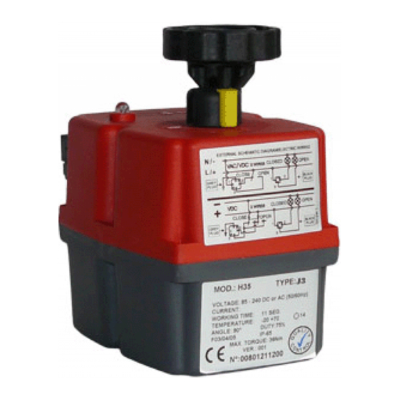
J3/ J3C / J3CS MODULATING ELECTRIC ACTUATOR
Movement of the actuator is proportional to input signal
Power is applied continuously. Movement of valve actuator is then controlled by an internally fitted digital position-
er and is proportional to changes supplied in an input control signal. This input signal is typically 0-10VDC, or 4-
20mA. An output signal is supplied as standard providing closed loop control. Fails closed on loss of control signal
(or see configuration options below), but stays put on loss of external power.
Configuration options:
1)
Closes on loss of control signal
2)
Opens on loss of control signal
3)
Stays put on loss of control signal (Fail freeze)
J3/ J3C / J3CS FAILSAFE MODULATING ELECTRIC ACTUATOR (same wiring as modulating version)
Combination of failsafe & modulating above:
Uses battery failsafe system and digital positioner to provide fail to safe position function on loss of external power.
J3 & J3C SERIES: ACTUATOR COVER & DIN PLUG IDENTIFICATION
Models: 20, 35, 55, 85
❷ ❸
❶
DIN Plug No
❶
❷
❸
DIN PLUG IDENTIFICATION
Models: J3-H, J3-L, J3C-H, J3C-L, J3CS
Colour
Grey plug & base
Black plug & base
Black plug & base
End of travel confirmation
Step by Step Wiring Diagram
J3 & J3C
Modulating Electric Valve Actuators
Models: 140, 300
❶
Connection
External power
Control signal (I/O)
J3 J3C Modulating Wiring Step by Step Rev 0 AVS
❷
❸
Advertisement

Related Manuals for AVS J3 Series

Summary of Contents for AVS J3 Series
- Page 1 Models: J3-H, J3-L, J3C-H, J3C-L, J3CS DIN Plug No Colour Connection Grey plug & base External power ❶ Black plug & base Control signal (I/O) ❷ ❸ Black plug & base End of travel confirmation J3 J3C Modulating Wiring Step by Step Rev 0 AVS...
- Page 2 Step by Step Wiring Diagram J3 & J3C Modulating Electric Valve Actuators ELECTRICAL CONNECTIONS (We recommend only qualified electrical engineers make the connections) 4-20mA or 0-10V Input WIRING DIAGRAM Volt free Customer supplied Position Confirmation External Power Control Signal I/O VAC/VDC Output VAC/VDC...
- Page 3 Step by Step Wiring Diagram J3 & J3C Modulating Electric Valve Actuators Control Signal Connections (Centre DIN Plug) Control Signal I/O Note: This Din plug is inverted to help prevent the possibility of the position confirma- Output tion plug being connected to the control connection, as doing so will irreparably dam- age the DPS positioner.
Need help?
Do you have a question about the J3 Series and is the answer not in the manual?
Questions and answers