Table of Contents
Advertisement
Quick Links
TECHNICAL AND
OPERATION
MANUAL
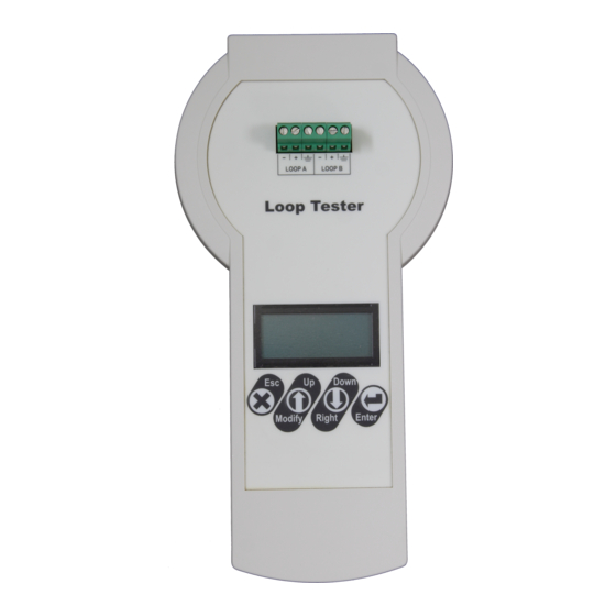
Loop Tester
Attention:
This manual contains information on limitations regarding product use and
function and information on the limitations as to liability of the manufacturer.
The entire manual should be carefully read.
The information in this manual is a subject to change without notice!
1
Advertisement
Table of Contents

Related Manuals for Teletek electronics Loop Tester

Summary of Contents for Teletek electronics Loop Tester
- Page 1 TECHNICAL AND OPERATION MANUAL Loop Tester Attention: This manual contains information on limitations regarding product use and function and information on the limitations as to liability of the manufacturer. The entire manual should be carefully read. The information in this manual is a subject to change without notice!
-
Page 2: Table Of Contents
3. Connection Diagrams............................4 3.1. Loop Connection ..........................4 3.2. Topology Diagrams .......................... 5 4. Operation with the Loop Tester ........................6 4.1. Switching on the Tester ........................6 4.2. Choosing a Language........................6 4.3. Reading a Topology of a Loop/Line ....................6 4.3.1 Reading of Unaddressed Loop/Line (New installations) ............ -
Page 3: Introduction
1.4. Preparing the joint connections The Loop Tester is delivered with a set of wires (2 red and 2 black) and clamp terminals for easier connection to the loop line. You can prepare the joint connections in advance and then follow the description in item 3. Connection diagrams. -
Page 4: Control And Operation Elements
The loop line must be disconnected from the control panel before connection to the Loop Tester! DO NOT connect the fire control panel and the Loop Tester to the loop line simultaneously! Connect the four ready joint connections (clamp terminal + wire) to the terminal row of the Loop Tester as strictly observe the polarity. -
Page 5: Topology Diagrams
Sub-branch of a branch on a loop Branches without separation In case of starting a test procedure of an unaddressed loop, the Loop Tester will set sequential addresses to the devices according their order in the loop: Addressing order in a loop with branch... -
Page 6: Operation With The Loop Tester
4.1. Switching on the Tester Power on the Loop Tester with the switch (item 2.1, position 5) moving in ON position. The display will show for a while the software version of the device and then will display the main operation menus. -
Page 7: Perform Cable Tests
Loop Tester – Technical and Operation Manual 4.4. Perform Cable Tests This is a menu for performing test of the fire cable used in the installation. The test can be fully automatic or manually selected separate single tests for different electrical values. It is recommended to run first the automatic test for reviewing the general state of the cable and then, if it is necessary, to proceed with single tests. -
Page 8: Single Cable Test
Loop Tester – Technical and Operation Manual 4.4.2 Single Cable Test Cable tests Auto Cable test Voltage side A Loop Tests Single Cable test Voltage side B Addressing R+ Cable Language R- Cable In “Single Cable test” sub-menu, all cable tests (see the table in item 4.4.1) are manually selected and performed according the current needs of the technician. -
Page 9: Perform Loop Tests
Loop Tester – Technical and Operation Manual 4.5 Perform Loop Tests This is a menu for performing test of the loop and the connected devices. It is recommended to run first the “Loop state” automatic test for reviewing the general state of the loop and a list of the connected devices. The general review will help you at the beginning to orientate for current faults, possible breaks or short-circuits in the loop, the number of connected devices and troubles with them. -
Page 10: Loop Tools
Loop Tester – Technical and Operation Manual 4.5.2 Loop Tools In this menu are available some test for finding troubles in existing loop installation. Cable tests Loop State Read parameters Loop Tests Loop Tools Short / Break Addressing Fire position... -
Page 11: Searching Short / Break Faults
Loop Tester – Technical and Operation Manual 4.5.5 Searching Short / Break Faults Attention: To perform accurate tests for finding of Short and Break position in the loop is mandatory all of the devices in the loop to have a built-in isolator module! The “Short / Break”... -
Page 12: Searching Of Devices In Fire Alarm Mode
Loop Tester – Technical and Operation Manual 4.5.6 Searching of Devices in Fire Alarm Mode In this menu the technician can review if there an activated manual call points in the system. The test can be performed for checking the correct operation of the connected call point to loop. Select “Fire position” and press ENTER button. -
Page 13: Checking The Operation Current
Loop Tester – Technical and Operation Manual Use the arrow buttons to select and address of a device and press ENTER button. A field “Turn ON” is appeared on the screen. Press ENTER button again to activate the LED indication of the device. The field is changed to “Turn OFF”... -
Page 14: Autoaddressing By Isolator Module
Loop Tester – Technical and Operation Manual 4.6.2 Autoaddressing by Isolator Module This way requires all of the devices connected to the line to have a built-in or connected to the loop isolator module. The tester starts the addressing of devices according their place following the order in the loop from side A to side B –... -
Page 15: Quick Menu Structure
Loop Tester – Technical and Operation Manual 5. Quick Menu Structure Appendix – SensoIRIS Devices Device Name Description Isolator Module Available S130 Optical-smoke detector S130 IS Optical-smoke detector Yes (built-in) T110 Temperature detector T110 IS Temperature detector Yes (built-in) M140... - Page 16 Loop Tester – Technical and Operation Manual www.teletek-electronics.com Address: Bulgaria, 1407 Sofia, 14А Srebarna Str. Tel.: +359 2 9694 800, Fax: +359 2 962 52 13 e-mail: info@teletek-electronics.bg 18021115, RevA, 11/ 2020...
Need help?
Do you have a question about the Loop Tester and is the answer not in the manual?
Questions and answers