Table of Contents
Advertisement
Quick Links
Advertisement
Table of Contents

Related Manuals for HMS CANnector

Summary of Contents for HMS CANnector
- Page 1 CANnector INSTALLATION GUIDE 4.01.0091.20000 1.3 en-US ENGLISH...
- Page 2 HMS Networks reserves the right to modify its products in line with its policy of continuous product development. The information in this document shall therefore not be construed as a commitment on the part of HMS Networks and is subject to change without notice. HMS Networks makes no commitment to update or keep current the information in this document.
-
Page 3: Table Of Contents
Installing on DIN Rail....................... 10 Installing the Adhesive Feet ..................... 10 Configuration........................11 Creating Configurations for CANnector S, L, SE, LE, LA ............11 Selecting Pre-Configured Configurations for CANnector Log, Bridge, Range ......12 6.2.1 Installing the Software ..................12 6.2.2... - Page 4 10 Support/Return Hardware....................27 10.1 Support ........................27 10.2 Return Hardware ......................27 11 Disposal..........................27 Regulatory Compliance ..................... 29 EMC Compliance (CE) ..................... 29 Disposal and recycling..................... 29 Open Source Software ...................... 29 4.01.0091.20000 1.3 en-US CANnector Installation Guide...
-
Page 5: User Guide
CANnector L 1.01.0091.00011 CANnector LA 1.01.0091.00100 CANnector SE 1.01.0091.00110 CANnector LE Pre-Configured CANnector Product Variants Concerning the hardware features the pre-configured CANnector product variants are based on the CANnector S device variant. Name Article number 1.01.0091.01000 CANnector Log 1.01.0091.02000 CANnector Bridge 1.01.0091.03000... -
Page 6: Trademark Information
User Guide 4 (30) Trademark Information ® Ixxat is a registered trademark of HMS Industrial Networks. All other trademarks mentioned in this document are the property of their respective holders. Conventions Instructions and results are structured as follows: instruction 1 ►... -
Page 7: Safety Instructions
Each product variant is ready-to-use due to the pre-configured basic configuration which is already loaded on the device. CANnector Log is used to log CAN, CAN FD, and LIN communication. CANnector Bridge is used to connect computer systems to CAN and CAN FD networks, to connect the networks with each other, and to change or manipulate the network data. -
Page 8: Scope Of Delivery
Included in scope of delivery: • selected CANnector variant • adhesive device feet • Installation Guide CANnector • power supply connector • USB cable • Ethernet cable • with CANnector Log: USB memory storage device 4.01.0091.20000 1.3 en-US CANnector Installation Guide... -
Page 9: Product Description
4.1.3 Software for Configuration The CANnector is a Linux platform that is able to work standalone without any connected PC. For the standalone function a configuration is needed, that can be created and downloaded to the device via a the PC based Advanced Configuration Tool (ACT). For more information see Creating Configurations for CANnector S, L, SE, LE, LA, p. -
Page 10: Cannector Log, Bridge, Range
Pre-Configured Product Variants CANnector Log With the CANnector Log the communication of the connected busses can be logged. The four provided basic CAN logging configurations (125 Kbit/s, 250 Kbit/s, 500 Kbit/s, and 1000 Kbit/s), that initializes all 6 CAN interfaces with the selected baud rate log all received data in csv format. -
Page 11: Software For Configuration And Visualization
Master configuration with 250 Kbit/s is loaded. An application on a Windows PC that is based on the Ixxat VCI driver can be extended with one CANnector Range, that is connected to the Windows PC. In that case the CANnector Range acts as remote PC interface connected via Ethernet. -
Page 12: Installation
► Stick the adhesive feet to the bottom of the device. ► Place the CANnector on an even surface. ► Make sure, that the venting slots are not covered and ensure adequate air circulation (recommended mounting distance: 2 cm distance to venting slots). -
Page 13: Configuration
Creating Configurations for CANnector S, L, SE, LE, LA The CANnector is a Linux platform that is able to work standalone without any connected PC. For the standalone function a configuration is needed, that can be created and downloaded to the device via a the PC based Advanced Configuration Tool (ACT). -
Page 14: Selecting Pre-Configured Configurations For Cannector Log, Bridge, Range
12 (30) Selecting Pre-Configured Configurations for CANnector Log, Bridge, Range To connect the CANnector to a PC via USB a driver is needed. With installation of the configuration tool ACT the driver is automatically installed (see Installing the Software, p. -
Page 15: Selecting A Pre-Configured Configuration
► activated on the Slave device (see Selecting a Pre-Configured Configuration, p. 13). If using the CANnector Log, the logging only starts if the USB memory storage device is plugged in correctly. 6.2.3 Selecting a Pre-Configured Configuration When the device is correctly connected the default configuration of the respective product variant is running (see Connecting the Device, p. - Page 16 Selected pre-configured basic application is running. After a power cycle the last selected configuration is automatically started. ► For more information about configuration possibilities of the product variants Log, Bridge and Range see respective User Manual on www.ixxat.com. 4.01.0091.20000 1.3 en-US CANnector Installation Guide...
-
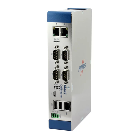
Page 17: Connectors
CAN 1 or if any CAN FD message is received on CAN 7. With the device variant CANnector LA it is possible to configure one specific CAN message ID or CAN FD message ID that switches on the device. For more information how to configure the Switch-on on CAN and the specific message see user manual IxAdmin. -
Page 18: Ethernet Connector (Lan)
X6 provides the EtherCAT-Slave-OUT function and X7 provides the EtherCAT-Slave-IN function. If the CANnector is connected to a EtherCAT Master solely, only X7 (IN) is used and X6 remains unconnected. The EtherCAT interfaces are galvanically isolated from the other interfaces. -
Page 19: Usb Slave Connector (Pc)
USB connection. When the CANnector is connected to test object, provide a grounded connection between the test object and the CANnector, before connecting a USB device to the CANnector (for example a USB based analog input extension). - Page 20 If LEDs 2-8 are flashing red, the Rescue Kernel is executed. ► Connect IxAdmin via Ethernet. ► To repair the device see information in online help IxAdmin. Restart the device. ► For more information see Rescue Kernel, p. 4.01.0091.20000 1.3 en-US CANnector Installation Guide...
-
Page 21: Field Bus Connectors X1, X2, X3, And X4
Signal Description CAN HS L High-speed CAN 3 low signal CAN FD L High-Speed CAN/CAN FD 5 low signal (only CANnector L, LE, LA) Common ground CAN HS H High-speed CAN 3 high signal CAN TX Disable RX only mode: when connected to GND, TX is disabled by hardware —... -
Page 22: Galvanic Isolation
7.7.1 Galvanic Isolation The CANnector has four interface islands on the D-Sub connectors X1, X2, X3 and X4. Each of the four islands is galvanically isolated from the other islands. Within an island the interfaces for CAN-FD, CAN high-speed, digital I/O, and LIN are galvanically connected to one another. The shielding of the cable and/or the metal collar of a D-Sub connector is directly connected to the housing. -
Page 23: Lin
If LIN is used, apply voltage of 12-24 V to the V-LIN connection. ► 7.7.5 Digital I/O The CANnector provides two digital I/O channels: • Each digital I/O channel has an output with a high-side switch (FET) and a comparator input with a Schmitt trigger function. -
Page 24: Additional Components
Additional Components 22 (30) Additional Components HMS Industrial Networks offers the following additional components. Connector Description Article number POWER 1.04.0089.00002 Cable with 3 banana plugs, 2.0 m (see Power Supply Cable, p. X1-X4 1.04.0089.00201 Dual CAN cable with D-Sub 9 and 2 x D-Sub 9, 1.5 m (see Dual-CAN Cable, p. -
Page 25: Dual-Can Cable
Dual-CAN male female Fig. 5 Dual-CAN cable Pin Allocation Cable Connector on the CANnector Connector CANnector Cable connectors CAN 1 Cable connectors CAN 2 HS-CAN 1 CAN-FD 7 HS-CAN 2... -
Page 26: Breakout Box For X1 To X4
24 (30) Breakout Box for X1 to X4 Depending on the device variant several interfaces are connected to the connectors X1 to X4. HMS Industrial Networks offers a breakout box to provide each of the interfaces on one connector. Fig. 6... -
Page 27: Breakout Cable For X1 To X4
25 (30) Breakout Cable for X1 to X4 Depending on the device variant several interfaces are connected to the connectors X1 to X4. HMS Industrial Networks offers breakout cables in different lengths to allow the creation of specific adapters. Fig. 7... -
Page 28: Technical Data
CAN transceiver high-speed Texas Instruments SN65HVD251 CAN-FD transceiver Microchip MCP2562FD None CAN bus termination resistor CAN signal delay with galvanic isolation: Typ. 27 ns LIN transceiver Microchip MCP2003B System startup time < 5 sec from power-on 4.01.0091.20000 1.3 en-US CANnector Installation Guide... -
Page 29: Support/Return Hardware
Support/Return Hardware 10.1 Support ► To contact support, go to www.ixxat.com/technical-support/contact-technical-support. ► Scroll down and click button mysupport.hms.se to register a support case. 10.2 Return Hardware www.ixxat.com/support/product-returns click button Portal to access the support portal. ► In the support portal select Submit Product Return (RMA). - Page 30 This page intentionally left blank...
-
Page 31: A Regulatory Compliance
When this product reaches its end of life, contact local authorities to learn about disposal and recycling options, or simply drop it off at your local HMS office or return it to HMS. For more information, see www.hms-networks.com. - Page 32 © 2021 HMS Industrial Networks Box 4126 300 04 Halmstad, Sweden info@hms.se 4.01.0091.20000 1.3 en-US / 2021-08-24 / 23086...
Need help?
Do you have a question about the CANnector and is the answer not in the manual?
Questions and answers