
Related Manuals for ITS Telecom 1700264

Summary of Contents for ITS Telecom 1700264
- Page 1 OPERATION MANUAL MITS J ANUS NGINE 1700264 UMBER September 29, 2020...
-
Page 2: Table Of Contents
MITS Janus Time Engine TABLE OF CONTENTS CHANGE HISTORY ..............................4 GENERAL DESCRIPTION ..........................5 (JTEMC) ....................5 ANUS NGINE ASTER ONTROLLER 1.1.1 Time Master ............................ 5 1.1.2 IRIG B Inputs ..........................7 1.1.3 1PPS Inputs ............................. 7 1.1.4 GPS Time Reference ........................8 1.1.5 PTPV2 Master Clock Function ....................... - Page 3 MITS Janus Time Engine 3.4.5 IRIG Delay Compensation ......................19 3.4.6 1PPS Reference ..........................19 3.4.7 GPS Reference ..........................19 ..............................20 UTPUTS 3.5.1 IRIG Frame ........................... 20 3.5.2 Clocks Frames ..........................20 3.5.3 Time Frame ........................... 21 3.5.4 Leap Second Adjust ........................21 ........................
-
Page 4: Change History
MITS Janus Time Engine CHANGE HISTORY Release Change Date 6/1/2020 Preproduction Release 6/9/2020 Modified commands per Engineering inputs; added return responses to queries. 6/25/2020 Production Release 9/25/2020 Updated the PTP Master commands, ^Y??x (two places as PTP mode and PTP Master settings). -
Page 5: General Description
MITS Janus Time Engine 1.0 GENERAL DESCRIPTION The MITS Janus Time Engine (MJTE) consists of a two-board set compliant with the physical dimensions of the PC104 standard. 1. The Janus Time Engine Master Controller (JTEMC), part number 1412413 2. Photo-Sonics Interface (PSI/O), part number 1412414 There is a stack interface connector between the two boards. - Page 6 MITS Janus Time Engine oscillator that disciplines an OXCO crystal. Disciplining strategy calibrates out any crystal frequency error (absolute and aging) and adjusts the drive clock to deliver a fixed number of counts between one-second ticks (fractional seconds). The scale of the fractional seconds is 25 nano seconds.
-
Page 7: Irig B Inputs
MITS Janus Time Engine Reference 1 Sec Tick Notes alignment 10±15 nanosec Not less than 3 satellites in view as reported by the GPS to (optional) establish a fix. One satellite required to maintain lock. 1.1.2 IRIG B Inputs The JTE Master Controller includes both IRIG B 12x or IRIG B 00x time code inputs. The system parses and decodes these streams when available to extract the year (if available), day, hours minutes and seconds that are encoded by the IRIG B time code signal (all ‘Control Function’... -
Page 8: Gps Time Reference
MITS Janus Time Engine 1.1.4 GPS Time Reference The optional GPS receiver will track up to 12 satellites and provide the absolute time and a 1PPS signal that is aligned to UTC within 30 nanoseconds when locked. When used, the time master may be synchronized to the internal GPS as the time reference. -
Page 9: Time Of Day Clock
MITS Janus Time Engine The JTE Master Clock uses the IEEE1588 default profile. 1.1.6 Time of Day Clock A Time Of Day (TOD) clock is provided that when the primary lithium cell is properly installed will maintain YYYY, MM, DD, HH, MM and SS values when powered down. TOD is not a low drift clock. -
Page 10: Settings Flash
MITS Janus Time Engine 1.1.9 Settings Flash The following settings are saved to MJTE system flash such that each will survive a power cycle. 1. Amplitude setting of IRIG B127 carrier output 2. DHCP enabled/disabled state 3. Network Time selection as NTP or PTP (slave) 4. -
Page 11: Photo-Sonics Interface (Psi/O)
MITS Janus Time Engine Photo-Sonics Interface (PSI/O) Controls and data received from the JTE Master Controller I/O Interface ensure properly synchronized timing and frequency outputs. The PSI/O also receives differential 1PPS and B00x signals and delivers them to the JTE Master Controller for time master synchronization. -
Page 12: Irig Btime Code Generator
MITS Janus Time Engine IRIG B time code generator The IRIG B time code generator samples the current time on the fractional second rollover of the time master and generates both B007 and B127 timecode streams. 1.3.1 An IRIG B127 output buffer The IRIG B127 AM signal stream is isolated from the output through an audio transformer having a 600 Ω... -
Page 13: Ntp Decode/Correction
MITS Janus Time Engine NTP Decode/Correction The NTP synchronizer requires a valid and reachable TCP/IP address to establish a client (JTE Master Controller)/server (NTP clock) relationship. Once a client session is begun with the NTP server, the JTE Master Controller will use its time and compensate for measurable loop delays. The JTE Master Controller adjusts the NCO frequency driving the time master such that there is a fixed number of counts between one second intervals such that the seconds rollover is aligned with the NTP server. -
Page 14: Home Page
MITS Janus Time Engine When Login Required After login or No Login Required Set username and password Home Page When the MJTE is first addressed by a browser one will see either a home page requiring a login (left) or the operating home page (right). After login, the home page on the right appears. When no Login Required If login is required, MJTE status (time, reference, IP address and mode will not be revealed until successfully logged in. -
Page 15: Admin Page
MITS Janus Time Engine UTC. The value set by Time Zone Offset is only used when locked to GPS, NTP or PTP. The time master also reports the current year either set by a manual entry, TOD read at startup or updated by the time reference being employed if available. -
Page 16: Change Login Page
MITS Janus Time Engine When Enable Login is checked the menu at the bottom of the pages adds Change Login and Log Out. For better security, the Enable Session Timer may be checked. When checked any value of Session Length greater than 0 will cause the session to self-terminate the indicated time in minutes after the next login. -
Page 17: Tcp/Ip Frame
MITS Janus Time Engine The drop down list (IRIG, GPS (if present), PTP/NTP, 1PPS) is the same in each selection, however, if IRIG is selected as priority 1 (as shown), this selection will not be accepted for any other priority. A priority level may not be skipped. -
Page 18: Network Time Reference
MITS Janus Time Engine 3.4.3 Network Time Reference The Network Time reference is comprised of two frames: the PTP Reference Clock and the NTP Server. Network Time is a choice for a time reference. The selection of NTP or PTP are mutually exclusive. -
Page 19: Irig Delay Compensation
MITS Janus Time Engine When DCLS is selected any IRIG B12X signal physically connected to the MJTE will be ignored. DCLS is an IRIG B00x TTL time code stream. There are several choices to make when using DCLS. The input selection may be either single-ended TTL (TTL) or differential RS485 (DIFF). -
Page 20: Outputs Page
MITS Janus Time Engine Outputs Page The Outputs page provides the ability to set the IRIG B127 peak-peak output level, set clock output frequencies and polarity, enter a time zone offset, manually input time and manually input the current value of leap seconds. 3.5.1 IRIG Frame The IRIG frame permits one to invert the IRIG B007 (DCLS) TTL output time code pulse train. -
Page 21: Time Frame
MITS Janus Time Engine 3.5.3 Time Frame The time frame provides a Time Zone Offset input. This value is only used when the time reference is any network time source (PTP or NTP) or when synchronized to the internal GPS (optional). Its value is intended to localize time from UTC. -
Page 22: Network Reference Settings Page
MITS Janus Time Engine In the event that the MJTE is set to perform as a PTP Master Clock, and the MJTE is synchronized by a 1PPS source, the current value of leap seconds must be manually entered such that the MJTE provided all of the synchronization data required by the IEEE1588 specifications for a master clock. -
Page 23: Ptp Master/Slave Mode Behavior
MITS Janus Time Engine profile set in the Master Clock to determine to which master to synchronize. This process may exclude the use of the MJTE if another master clock is present, visible on the same network and deemed the best master clock. The MJTE may never both act as a master and slave at the same time for any protocol (PTP or NTP). -
Page 24: Ascii Command Set
MITS Janus Time Engine 4.0 ASCII COMMAND SET The table below is a list of commands that can control the setup of JTE. All commands are ASCII strings specified. When ^Y is used in a command string, it is the HEX value of 19, ^S is HEX 13, ^T is HEX 14 Group Command String... - Page 25 MITS Janus Time Engine Group Command String Variable values Notes ^YCA? Queries current value Return =(19h)CA(32h)valueHZ<CR> as ASCII Value= 1Hz,10Hz,100Hz,1kHz,10kHz,100kHz, 1MHz or 10MHz Example: (19h)CA 10Hz<CR> Clocks Clock B Out ^YCBxxxx<CR> Where xxxx=0001 (default) to 1000 The value of xxxx produces an output of 1 to 1000 Hz, respectively.
- Page 26 MITS Janus Time Engine Group Command String Variable values Notes IRIG IRIG Delay ^YICAnnnnn Where nnnnn is any positive integer This value only applies to value from 0 to 1600 which represents a time received from an Comp multiplier for 125 ns. The value of IRIG B12x source.
- Page 27 MITS Janus Time Engine Group Command String Variable values Notes ^YII? Queries current value Return=(19h)II(32h)value<CR> as ASCII Value=1 or 0 IRIG Set IRIG B127 ^YILaa aa = 10 to 99 The value aa *100 is the output number of millivolts p-p Factory default is 30 (3Vp-p) amplitude of the output.
- Page 28 MITS Janus Time Engine Group Command String Variable values Notes address assigned to the unit. Netwrk DCHP or Status ^YDHn n=’0’; disable DHCP ITS offers an ITS Client IP mode n=’1’; enable DHCP (factory default) Discovery software that can detect and report the current IP address of any of its products on your network.
- Page 29 MITS Janus Time Engine Group Command String Variable values Notes PTP/NTP x= P,N,S ^YTSxn Network when x=P (PTP master/slave) n= 0,1 Time Source 0=Master 1=Slave when x=N (NTP master/slave) n= 0,1 0=Master 1=Slave when x=S (NTP/PTP as source) n= 2,3 2=NTP as source 3=PTP as source Queries the current value...
- Page 30 MITS Janus Time Engine Group Command String Variable values Notes order. That is, 1,2,3,4. Time PRIORITY B ^YPBx x=1,2,3,4 where You may not skip a source 1 = IRIG priority (e.g. 1,3,4). 2 = GPS (if present) Skipping a priority will 3 = PTP/NTP (factory default) cause the round robin 4 = 1PPS...
- Page 31 MITS Janus Time Engine Group Command String Variable values Notes ^YTZ? Queries current value Return =(19h)TZ(32h)SHH:MM<CR> as ASCII Where S=+ or - HH = 0-12, MM=00,15,30, or 45 Time Manually Set ^T (14Hex) Where Set time. Time is entered Setting time yydddhhmmss<CR from left to right,...
- Page 32 MITS Janus Time Engine Page 32 of 39 Copyright© Instrumentation Technology Systems 2020 20200929...
-
Page 33: Physical Characteristics
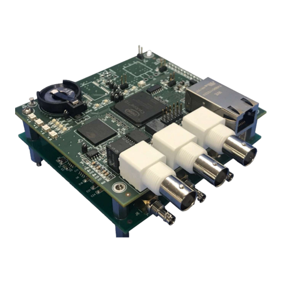
MITS Janus Time Engine 5.0 PHYSICAL CHARACTERISTICS The MJTE is a two-board set preassembled into a PC104 style assembly. The mounting hole placement, board size and connector locations comply with the specifications of PC104 as shown. Components Optional w/GPS Holder for Lithium button primary cell for TOD and GPS PS I/O... -
Page 34: I/O Connectors
MITS Janus Time Engine I/O Connectors The I/O connectors are identified by name in the images above. Each such connector is identified below specifying the appropriate mating connector. I/O Connector Type Where Mate AM IRIG in, IRIG DCLS in, CLOCK in BNC (3) GPS (optional) Master... -
Page 35: J4 Differential Outputs, Ps I/O Board
MITS Janus Time Engine 5.1.2 J4 Differential Outputs, PS I/O board DIFFERENTIAL OUPUTS J4 1PPS_OUT n/1PPS_OUT GROUND GROUND DCLS_OUT n/DCLS_OUT 5.1.3 J9 Power Connector, PS I/O board POWER J9 GROUND GROUND +12VDC +12VDC Page 35 of 39 Copyright© Instrumentation Technology Systems 2020 20200929... -
Page 36: Switches And Indicators
MITS Janus Time Engine Switches and Indicators The JTE Master Controller has several controls and indicators that are used to set conditions and report running status. Startup Status Config done= FPGA HW load OK S2: Reset IP address to default, reset NTP Init Done=FW load OK address to default, use static IP address. -
Page 37: Specifications
MITS Janus Time Engine 6.0 SPECIFICATIONS Function Parameter Specification Notes Time Master Unlocked Drift ±36 µS/hour After 1 hour of continuous operation locked to a time reference. Locked to IRIG 750±250 B120 and B123 do not include the year B12x nanoseconds which must be manually set. - Page 38 MITS Janus Time Engine Function Parameter Specification Notes IRIG B12x AM modulated time code stream is a transformer isolated, Input 600 Ω input impedance. Synchronization to this input is highly dependent on the signal quality, p-p amplitude of the carrier at the destination and accuracy of the receiving time code decoder.
- Page 39 MITS Janus Time Engine Function Parameter Specification Notes 1PPS out Phased locked such that the leading edge of the clock will align to the fractional second rollover (1 second tick) to ±25 nanoseconds. Drives up to 10 TTL loads up to 100 meters over 50Ω coax. Physical output is configurable to be single ended or differential drive and deliver pulses with the rising or falling edge coincident with the time master one second rollover.
Need help?
Do you have a question about the 1700264 and is the answer not in the manual?
Questions and answers