
Related Manuals for Mielta Katana


Summary of Contents for Mielta Katana
- Page 1 Fuel level sensor «Katana» Setup and Operation Manual Hardware version 12 Software version 2.2.2 Configuration program version 2.1.0 Amended on 13.08.2021 Tambov 2022...
-
Page 2: Table Of Contents
Table of contents Description Specification Power supply Frequency output RS485 interface Installation and Connection Configuartion of the sensor Connection to the sensor Calibration Taring Other settings Transportation and storage Warranty terms Package contents... -
Page 3: Description
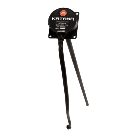
Description Fuel Level Sensor (FLS) Katana MIELTA is designed to measure the level of light petroleum hydrocarbons (diesel fuel, gasoline, kerosene, etc.) in containers for various purposes. Sensor can be installed both on stationary objects, and on vehicles and railway transport. -
Page 4: Specification
Specification Table 1. Supply voltage 8 – 55 V Average power consumption 0,5 W Measurement period 1 sec Average interval 1-60 sec Relative level measurement error over the entire range Frequency output: maximum frequency range 30-2047 Hz Frequency output discreteness 1 Hz Frequency output pull-up to the power supply 3.3 В, 470 kOhm... -
Page 5: Rs485 Interface
The RS485 interface allows you to connect several sensors to one terminal port (Pic. 1, 2). All MIELTA satellite terminals support the connection of up to 8 any sensors or peripherals on the RS485 bus. -
Page 6: Installation And Connection
When connecting several sensors at a distance less than 20 m from a tracker, the "star" scheme is recommended. This scheme does not require additional terminal resistors.. Picture No 2. Type "bus" connection scheme. The "bus" scheme connection is used to connect several sensors at distances up to 100 m. - Page 7 Picture No 3. Mounting dimensions of FLS. The central hole has a Ø25 mm diameter (Pic. 3). The mounting holes diameter is chosen based on the material of the fuel tank and the fixation method. Self-tapping screws are used to fix the sensor. When the sensor is mounted on a metal tank, It is drilled 4 holes with a diameter of 4-4.5 mm or It is used screws with a drill.
- Page 8 Picture No 4.Dimension of FLS. Installation procedures: 1. Select a location for installation, clean it of contamination. 2. Mark the holes according to the template, drill and remove the sawdust. 3. Measure the depth of the tank from the bottom to the mounting surface. 4.
- Page 9 The operations sequence during bending: Disconnect sensor from the power supply; 2. Calculate the location of the fold, mark it on the sensor tube; 3. Place the sensor tube in the pipe bend with a mark in the middle; 4. Connect the measuring device (multimeter) in the continuity mode with probes to the tube and the central electrode, respectively;...
-
Page 10: Configuartion Of The Sensor
Рисунок 7. Нумерация контактов в Рисунок 6. Нумерация контактов в разъеме разъеме ДУТ. жгута. ● All electrical connections must be soldered or crimped. Seal the joints using a heat-shrinkable adhesive tube. Configuartion of the sensor To configure the Sensor use the configurator program. Viewing Sensor information is available without limitations, and to change the settings is required a password. -
Page 11: Connection To The Sensor
Connection to the sensor Connection to the sensor is possible via the RS-485 interface with using a special adapter. Before you start working with the sensor, you need to search for devices on the RS-485 bus. To do this, click the "Sensor Select" button, which is located in the "General" menu of the configuration program (Picture. -
Page 12: Taring
4. After stabilizing the readings in the program, perform calibration on a "full tank" (Picture 10). Remove the Sensor from the fuel tank, let the remaining fuel drain for 5 minutes. 6. After stabilizing the readings in the program, perform calibration on a "empty tank”... -
Page 13: Other Settings
to an Excel file, printed out. Moreover, you can import a table from an Excel file. If a taring table has already been recorded in the sensor, you can download it from the Sensor to the configuration program using the "Read table" button (Picture 11 Picture 11. - Page 14 operating time and the number of starts in the internal memory. To view the log of changing settings, use the "Log" program menu (Picture 12). Picture 12. Sensor settings change log. To download a log from the Sensor, click the "Get log data" button. To save the log to a text file, click the “Export to File”...
- Page 15 To change the user's password, click the "Change password" button, in the opened window enter the current and new passwords and click "Change" (Picture.14). Picture14. . Change user's password. ● If the user's password is lost, it is possible to reset the user's password To get a master password, contact your hardware vendor.
-
Page 16: Transportation And Storage
- for the sensors which failed due to incorrect software update. Package contents Name Quantity FLS Mielta KATANA Mounting cable Mounting kit: - Gasket - Pipe bottom cap...
Need help?
Do you have a question about the Katana and is the answer not in the manual?
Questions and answers