
Subscribe to Our Youtube Channel
Related Manuals for eta BE-P3


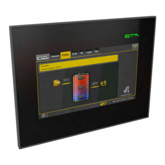
Summary of Contents for eta BE-P3
- Page 1 2017-08-23 0000000360 V.003 X.35.6, X.40.1 939016-002 Replacing the control panel on the BE-P3 Installation...
- Page 2 ETA Heiztechnik Gewerbepark 1 A-4716 Hofkirchen an der Trattnach Tel: +43 (0) 7734 / 22 88 -0 Fax: +43 (0) 7734 / 22 88 -22 info@eta.co.at www.eta.co.at...
-
Page 3: Table Of Contents
Exchanging a BE-P3 ........ -
Page 4: General Information
Properly dispose of parts which are no longer required. All parts which are no longer required must be disposed of properly and not sent back to ETA. Only parts which are still subject to warranty or guarantee claims are to be returned to ETA. -
Page 5: Preparation
Software version 3.35.X is already installed on the new software versions for the user interface up to "BE-P3" control panel. That is why you should check X.35.X (1.35.X, 2.35.X and 3.35.X) and the versions the installed software version on the defective control from X.36.0 (e.g.: 2.39.0 and 3.39.0). -
Page 6: Read Out Node Number
If there is a registration for "meinETA" on the defective control panel, this must be deleted before the exchange (if possible). Note down the access details for "meinETA" in order to register the new control panel after the exchange. See chapter 4.3 "meinETA remote control". www.eta.co.at... -
Page 7: Installation
Installation Exchange for PelletsUnit/ PelletsCompact Installation Assembly and installation only by qualified First, remove the panelling on the top. To do so, specialist personnel completely unscrew the cheese-head screw next to the flue connection to the chimney. Next, press the lock The assembly and installation may be performed and lift off the panel. - Page 8 If a network cable was previously connected, carefully install it with two screws. Note the correct also connect it to the control panel. alignment of the control panel. The ETA logo must be on top. Fig. 3-7: USB adapter cable Fig.
-
Page 9: Exchange For Hack, Sh, Pe-K
Installation Exchange for HACK, SH, PE-K Exchange for HACK, SH, PE-K Disconnect the earthing cable of the cover from the insulation door terminal. Technical illustrations The following describes how to exchange the control panel of the wood chip boiler and is also applicable to the HACK and PE-K boilers. - Page 10 Fig. 3-15: Break off tabs Insert the new control panel and carefully attach it with the retaining plate and two screws. Note the correct alignment of the control panel. The ETA logo must be on top. Fig. 3-13: Side view with enlarged cut-out Fig.
- Page 11 Installation Exchange for HACK, SH, PE-K If the cut-out has been enlarged, the tabs are left Connect the USB adapter cable (part of delivery on the retaining plate. scope) to the control panel and the existing boiler USB cable. If a network cable was previously connected, also connect it to the control panel.
-
Page 12: Exchange For Hack Vr
If this is not desired, the cut-out can be enlarged panel. so that the new control panel is more flush with the cover. A cutting template for this can be seen in chapter 5 "Cutting template". Fig. 3-22: Control panel Fig. 3-24: Side view with enlarged cut-out www.eta.co.at... - Page 13 Fig. 3-26: Break off tabs Insert the new control panel and carefully attach it with the retaining plate and two screws. Note the correct alignment of the control panel. The ETA logo must be on top. Fig. 3-29: USB cable...
-
Page 14: Exchanging A Be-P3
If a network cable was previously connected, Replacing the "BE-P3" control panel also connect it to the control panel. The "BE-P3" control panel is replaced by a new "BE- P3" in the same way as described in the previous chapters. However, only the control panel is exchanged, the brackets and the USB lines are not required. -
Page 15: Concluding Activities
Concluding activities Setting node numbers Concluding activities Setting node numbers 4.1.2 Software version X.36.0 and later Set node number on ETAtouch control panel Set node number 1. Switch on the entire heating system. Setting the node number on the new control panel set is only required if several control panels are present in 2. -
Page 16: Etatouch Software Update
You can find the files required for the software update 2. Press the button on the ETAtouch control in the login area of the www.ETA.co.at website, and panel. Then press the [Change authorisation] also on www.meinETA.at. button. A window opens. Enter the password "135"... -
Page 17: Software Version X.36.0 And Later
5. Enter the boiler number. [Software update] button. If an update is 6. Press [Register]. available, it will appear on the screen. The data are transferred to ETA and the ETAtouch controller is registered for this user. 4.3.2 Software version X.36.0 and later Registering the ETAtouch controller 1. -
Page 18: Cutting Template
Cutting template Cutting template Cutting template for BE-P3 The cutting template is depicted at 1:1 scale. www.eta.co.at... - Page 20 DOWNLOAD www.eta.co.at...
Need help?
Do you have a question about the BE-P3 and is the answer not in the manual?
Questions and answers