
Related Manuals for Intimus POWERCUT 7310 EPSHP


Summary of Contents for Intimus POWERCUT 7310 EPSHP
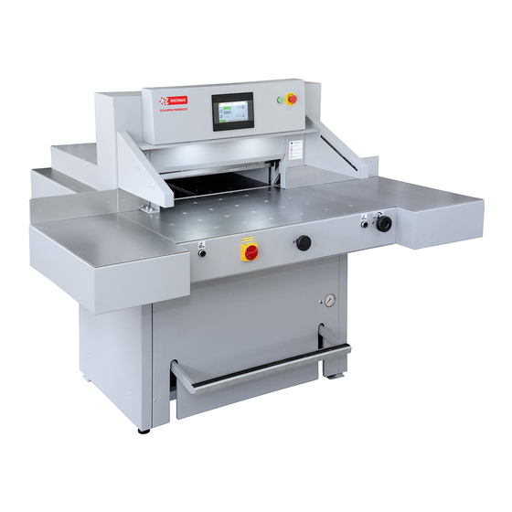
- Page 1 7310 EPSHP Single Knife Paper Cutter Operation Manual intimus International GmbH, Bergheimer Straße 6-12, 88677 Markdorf / Germany Tel.: ++49 (0)7544 / 60-0 --- E-mail: sales.de@intimus.com --- www.intimus.com 95843 1 04/21...
-
Page 2: Table Of Contents
Operation Manual 7310 EPSHP Content 1. GENERAL INFORMATION ....................6 1.1 Identification........................6 1.2 Purpose of use ......................7 1.3 Documentation ......................7 1.4 Introduction ........................7 2. SAFETY OF USE ....................... 8 2.1 Symbols: meaning and application ................9 2.2 Employee qualifications .................... - Page 3 Operation Manual 7310 EPSHP 8. OPERATIONAL ACTIVITIES ................... 38 8.1 Replacing the knife in the cutter .................. 38 8.2 Reversing or replacing the cutter bar ................50 8.3 False clamp ........................ 51 8.4 Adjusting the parallelism of backguage ............... 54 9.
- Page 4 Operation Manual 7310 EPSHP IDENTIFICATION Machine type: Single knife paper cutter Item: INT-GU-07310EPSHP...
- Page 5 Operation Manual 7310 EPSHP EC-Conformity Declaration...
-
Page 6: General Information
1. GENERAL INFORMATION This operator manual introduces the machine for the user and shows what for the • machine was designed for to enable safe and comfortable work on the machine Inside the manual there are listed special safety requirements necessary to use the •... -
Page 7: Purpose Of Use
Operation Manual 7310 EPSHP 1.2 Purpose of use This Single knife cutter is designed for cutting to requested dimension reams of paper, cardboard and other materials like pvc, plastics, fiber, foils, lamination and rubber etc. It is mainly used by printing houses, print finishing specialists, copy shops and offices. In case of some materials (like ex. -
Page 8: Safety Of Use
Operation Manual 7310 EPSHP 2. SAFETY OF USE The mechanical, electrical and electronic cutter assemblies were made according to state-of- the-art solutions and generally accepted technical rules that ensure safety in the event of a failure. Appropriate safeguards provide the operator with the highest level of security. The use of accessories or accessories that have not been mounted, delivered or manufactured by the cutter manufacturer requires a special permission from the manufacturer. -
Page 9: Symbols: Meaning And Application
Operation Manual 7310 EPSHP 2.1 Symbols: meaning and application Table 1: Symbols meaning • Read operator manual • Respect operator manual INFORMATION • WARNING! • • Risk of machine damage • Risk of deterioration of technical condition of machine • CAUTION! DANGER! •... -
Page 10: Requirements For The Operator's Workplace
Operation Manual 7310 EPSHP Info Before operating the cutter the operator must read the operating instructions. • Every employee delegated to work during assembly, disassembly, reassembly, commissioning, servicing and maintenance (technical inspection, servicing, repairs) of the cutter must read the entire operating manual, in particular the chapter "Safety of use". - Page 11 Operation Manual 7310 EPSHP The operator himself must also make sure that the machine is not operated by unauthorized persons! Table 2: List of threats occurring while operating the cutter Factor/notification Type of threat Mechanical hazards Motor, belt transmission of the mechanism of backguage Catching, crushing The lever system of the knife drive mechanism Catching, crushing...
-
Page 12: Description And Evaluation Of Residual Risk
Operation Manual 7310 EPSHP 2.5 Description and evaluation of residual risk intimus International GmbH takes responsibility for the construction of the guillotine in order to eliminate the danger, although some risk elements during the cutting machine operation are possible. Residual risk resulting from incorrect behavior of the cutter operator. -
Page 13: Ways To Prevent Threats
Operation Manual 7310 EPSHP 2.7 Ways to prevent threats Figure 3 Arrangement of covers and protective elements... - Page 14 Operation Manual 7310 EPSHP Table 3: Safety measures used to eliminate hazards (according to Figure 3) Factors and / or dangerous places Security measures Identification MECHANICAL The lever assembly mechanism of the Fixed cover 1, 3, 4, 10, 11 pressure beam drive Machine body Emergency stop Hydraulic system...
-
Page 15: Safe Working Rules
Operation Manual 7310 EPSHP 2.8 Safe working rules 1. Training of the operator: • aware of the potential hazards that may occur when operating the machine • clearly defining activities which, under the conditions of a given plant, are or are not the responsibility of the cutter operator and are reserved for designated authorized persons, in particular as regards the removal of defects and repairs - including electrical installations. -
Page 16: Transport And Storage
Operation Manual 7310 EPSHP 3. TRANSPORT AND STORAGE 3.1 Packaging 3.1.1 Characteristics of the packaging The transport packaging used is a disposable packaging. The transport platform is made of wood and the outer packaging is made of cardboard. Inside the box the cutter and accessories are packed in anti-corrosion covers made of plastic and oiled paper. - Page 17 Operation Manual 7310 EPSHP Figure 5a Transporting the cutter in the crate using a forklift. Figure 5b Transporting cutters with a pallet truck...
-
Page 18: Delivery Status
Operation Manual 7310 EPSHP Figure 5c Removing covers 3.3 Delivery status The cutter is supplied by the manufacturer with the disassembled side tables (assembly of the tables according to Figure 6) Fig 6. Tightening of side tables 1. Left side table + screw M10x20 (4 pcs) + washer 8 (4 pcs.) 2. -
Page 19: Setting The Cutter
Operation Manual 7310 EPSHP DANGER! Protect the power cables from sharp tools, high temperature and oil. 3.4 Setting the cutter Figure 7 Adjusting the cutter setting. The cutter does not need to be attached to the ground. The correct and safe setting of the machine is achieved by turning the adjusting foot 1, and locking its position with the nut 2, as shown in Figure 7. -
Page 20: Work Area
Operation Manual 7310 EPSHP 3.5 Work area In order to easily access the cutter's mechanisms during adjustment, maintenance or servicing activities, it is recommended to keep a free space of about 0.5 m around the device. (Fig.8) Figure. 8... -
Page 21: Technical Characteristics Of The Guillotine
Operation Manual 7310 EPSHP 4. TECHNICAL CHARACTERISTICS OF THE GUILLOTINE 4.1 Destination The cutter is intended for trimming the required size of a stack of paper, cardboard and other materials: plastics, fibers, metal foil, laminate, rubber, etc. It is mainly used in printing houses, bookbinding shops and offices. - Page 22 Operation Manual 7310 EPSHP 4.2.3 Technical data - hydraulic system 4.2.3.1 Technical data - hydraulic power supply Table 6: Parameter 7310 EPSHP Motor (kW) Voltage / frequency 3x400/50 2x220/60 (V/Hz) Control of executive elements (VDC) Tank capacity (l) 4.2.3.2 Technical data – hydraulic oil Table 7: Parameter 7310 EPSHP...
- Page 23 Operation Manual 7310 EPSHP 4.2.4 External dimensions The dimensions of the machine are shown in figure 9 and table 8. Figure 9 Dimensions of the cutter Table 8: Dimension Value (mm) 1445 1754 1857 1105 Y program Y1 manual...
-
Page 24: Operation
Operation Manual 7310 EPSHP 5. OPERATION 5.1 Operating safety 5.1.1 Safety instructions Before each start-up or start-up on the cutter, the next change should be made to • ensure that the safety components are complete and work properly. The cutter can only be operated if all safety components and safeguards such as •... - Page 25 Operation Manual 7310 EPSHP Figure 10 Controls and signaling elements of 7310 EPSHP cutting machine 1. Main switch 2. Palm button, (emergency stop) 3. Locking button of the control system 4. Button that activates the control system. 5. Buttons enabling the cutting cycle (two-handed cutting start-up system) 6.
- Page 26 Operation Manual 7310 EPSHP Figure 11 Receiver indicators The receiver is equipped with six LEDs informing about the operating status: Table 9: Item Color of the LED Display Text Red/green Status OSSD OSSD Error indication Blue Quality of setting 1234 Blue LEDs inform about the quality of the settings, in conjunction with the flashing red color LED ERR, also indicate errors.
-
Page 27: Electrical Apparatus
Operation Manual 7310 EPSHP Figure 12 Transmitter Indicators The transmitter is equipped with two LEDs informing about the operating status: Table 11: Position LED diode colour Indication Text yellow Work status indicator Error indication 5.3 Electrical apparatus The cutter is supplied with a five-core copper wire with 2.5 mm2 wire cross-section. The user's duty is to install the cutter to the electrical network with 20 A safeguards. - Page 28 Operation Manual 7310 EPSHP 1. Hinged housing of electrical apparatus (Fig. 13) 2. Nuts fixing the housing (Fig. 13) Figure 13 Location of electrical apparatus...
-
Page 29: Power Supply
Operation Manual 7310 EPSHP 6. POWER SUPPLY Figure 14 Location of the nameplate Data on the plate: 400V power supply 50-60 Hz frequency 3 kW power 20 A protection WARNING! The data on the plate must correspond to the current parameters in the mains! Parameters of frequency converters (inverters) are set by the cutter manufacturer and can not be changed! -
Page 30: Using The Cutter
Operation Manual 7310 EPSHP 7. USING THE CUTTER The user is obliged to create working conditions at the cutter workplace that preclude the operator from slipping or falling due to poor ground conditions, cable routing the wires or lack of convenient access! 7.1 Work area for operational staff The working area is the front side of the (operational) cutter! 7.2 Danger zones in the cutter... - Page 31 Operation Manual 7310 EPSHP 1. Set the main switch 1 to "ON" 1 position (Fig. 15) 2. Press the green button 2 (Fig.15) - LED 3 lights up green - the green OSSD 1 LED lights up (Fig.11) in the receiver 4 (Fig.15) INFO If after turning on the power supply with the main switch 1 (Fig.
-
Page 32: Determining The Position Of The Approaching Beam
Operation Manual 7310 EPSHP 7.3.2 Diagnostics of the light curtain after switching on the power supply. When the cutter is switched on, the transmitter 1 and receiver 2 are initialized (fig. 16). All transmitter and receiver LEDs will light for a moment. After initialization the receiver indicates the quality of the setting using four blue LEDs 3 (Fig.11). - Page 33 Operation Manual 7310 EPSHP INFO The method of determining the position of the beam as well as the operation of the programmer are described in the "Instruction for program unit".
-
Page 34: Pressing The Material
Operation Manual 7310 EPSHP 7.4.1 Changing the position of the beam with the handwheel 1. Press knob 2 (Fig. 17) 2. Turn the knob to bring the beam closer or closer by reading the position value on the programmer screen. Figure 17 Arrangement of the positioning elements of the backguage 7.5 Pressing the material The pressing of the cut material takes place automatically after pressing the buttons that start... - Page 35 Operation Manual 7310 EPSHP Figure 18 Operating elements when used during pressing. 7.5.2 Change of clamping force Changes in the clamping force are made by the knob 1, reading the pressure value on the pressure gauge 4 (Fig.18) turning to the right - increasing the pressure turning to the left - reducing the clamping force Approximate values of the clamping force depending on the pressure value read on the pressure gauge (manometer) 4...
-
Page 36: Cutting Line Indicator (Optical)
Operation Manual 7310 EPSHP 7.5.3 Rules for selecting the contact pressure. The value of pressing force is selected experimentally, in relation to the type, width and height of the cut material. The following rules must be observed: the higher the pile, the greater the downforce the greater the cutting width, the greater the downforce the harder the material, the greater the downforce 7.6 Cutting line indicator (optical) - Page 37 Operation Manual 7310 EPSHP Cutting can be done if: 1. there is no object in the work area of the light barrier - the green OSSD 1 LED lights up (Fig.11) on the receiver 1 (Fig.19). 2. the green push button switch 2 is pressed. 3.
-
Page 38: Operational Activities
Operation Manual 7310 EPSHP 8. OPERATIONAL ACTIVITIES 8.1 Replacing the knife in the cutter It is recommended, on the basis of experience, to change the knife to sharp after about 8 hours of effective, continuous work. DANGER! Do not put hands into the cutting zone! Danger of injury to the operator and auxiliary personnel •... - Page 39 Operation Manual 7310 EPSHP 8.1.1 Removing the knife Figure 21 8.1.1.1 Select the "Change knife" function on the programmer 1 screen (Fig.21) ("Programmer's manual"). 8.1.1.2 Pressing the push buttons 2 (fig.20) at the same time, start the cutting cycle. The knife 3 is held in the lower position. 8.1.1.3.
- Page 40 Operation Manual 7310 EPSHP 8.1.1.4 Remove the two screws 1 (fig.22) securing the cover 2 and remove the cover 2. Figure.23 8.1.1.5 Unscrew and remove the first fastening screw 1 from the right side of the cutter bar (Fig. 23). 8.1.1.6 Switch on the power supply of the electrical system by turning the main switch knob 2 (fig.23) to position "I"...
- Page 41 Operation Manual 7310 EPSHP Figure 24 8.1.1.10 Unscrew and remove the fastening screws 1 and 2 (Fig. 24). 8.1.1.11 In the place of screws 1 and 2 removed (fig.24), screw in the transport handle 1 (fig.25), so that it secures the knife to the cutter bar. 8.1.1.12 Unscrew and remove the screws 2 (fig.26) Figure 25...
- Page 42 Operation Manual 7310 EPSHP Figure 26 Figure 27...
- Page 43 Operation Manual 7310 EPSHP Figure 28 8.1.1.13 holding the transport handles release the clamp by turning them 1/2 turn at a time to the left (fig 27) and carefully pull the knife down (fig 28). Take the removed knife into the special protective packaging (Fig.
- Page 44 Operation Manual 7310 EPSHP Figure 29c Unscrewing / securing the transport handles Figure 29d Fixing the knife in the package 1. Packaging 2. Cover 3. Screw 4. Nut 5. Washer 6. Knife 7. Knife change holder...
- Page 45 Operation Manual 7310 EPSHP 8.1.2 Inserting a knife 8.1.2.1. Remove all adjusting screws 1 (figure 30) so that their faces are hidden in the knife bar body. Figure 30 B - the adjusting screw does not protrude below the protrusion 2 in the cutter bar - correct position.
- Page 46 Operation Manual 7310 EPSHP 8.1.2.2. Remove the knife from the packaging (Fig.29a - 29d) 8.1.2.3. Holding the transport handles 1, insert the knife 2 into the cutter so that the transport handles screwed into the knife hit the cutouts in the cutter bar 3. (fig.31) Figure 31 Insert the knife so high that its upper surface will rest against the protrusion in the knife bar 2 (Fig.
- Page 47 Operation Manual 7310 EPSHP 8.1.2.4 Pre-attach the knife to the cutter bar by turning both transporting handles 1 to the right (fig. 32). 8.1.2.5 Install the fastening screws 2 (fig. 32). 8.1.2.6 Unscrew both transport lugs 1 (figure 33) and replace them with the mounting screws 1 and 2 (fig.
- Page 48 Operation Manual 7310 EPSHP Figure 34 8.1.2.11. Screw in the bolt 2 lightly (fig.34). 8.1.2.12. Unscrew the fixing screws 4 (fig.35) so that the knife falls under its own weight on the base bar with its entire length. 8.1.2.13. Tighten the adjustment screws 5 (fig. 35) as far as they will go, so that the blade of the knife is cut into the base bar, approx.
- Page 49 Operation Manual 7310 EPSHP WARNING! Performing too deep cuts may result in shortened blade life!. 8.1.2.14. Tighten the mounting screws 4 (figure 35) 8.1.2.15. Switch on the power supply of the electrical system by turning the main switch knob 3 (fig. 35) to position "I". 8.1.2.16.
-
Page 50: Reversing Or Replacing The Cutter Bar
Operation Manual 7310 EPSHP 8.2 Reversing or replacing the cutting sticks DANGER! Risk of injury! The cutting quality of the lower stack sheets and the speed of blunting of the knife depend to a large extent on the cutting stick. Replacing or reversing the cutting stick is recommended after each knife change or in the event of breaking (not cutting) the lower sheets. -
Page 51: False Clamp
Operation Manual 7310 EPSHP 8.2.1 Lift the cutting stick 1 with a screwdriver 4 (fig. 37) 8.2.2 Rotate or replace the cutting stick 8.2.3 Insert the replaced stick into the channel between the tables 2 and place it on the dowel 3 (Fig. - Page 52 Operation Manual 7310 EPSHP The pressure beam insert (fig. 39) is attached under the front table in the place shown in figure 40. Figure 40 Placement of the insert before attachment in the pressure bar DANGER! Risk of injury! In order to mount the insert in the pressure bar: 8.3.1 Place the insert 1 (Fig.
- Page 53 Operation Manual 7310 EPSHP 8.3.2 Pressing pedal 2 (Fig. 41), bring the pressure beam down so that the insert pins hit the holes in the beam and the insert adheres the entire surface to the bottom surface of the beam. 8.3.3 Use a 3-mm hexagonal key with 3 mm to firmly screw in the screws 3 (Fig.
-
Page 54: Adjusting The Parallelism Of Backguage
Operation Manual 7310 EPSHP 8.4 Adjusting the parallelism of backguage Depending on the required inclination of backguage, it must be adjusted using drawings 42 and 43. Figure 42 How to remove the cover To adjust backguage: 8.4.1 unscrew the screws 1 (fig.42) 8.4.2 remove the cover 2 (fig.42) 8.4.3 loosen the screws 1 (fig.43) 8.4.4 loosen the nuts 2 (fig.43) - Page 55 Operation Manual 7310 EPSHP Figure 43 Adjusting elements of backguage...
-
Page 56: Maintenance
Operation Manual 7310 EPSHP 9. MAINTENANCE DANGER! Maintenance and lubrication work may only be carried out after turning off the machine (main switch in position "0"). 9.1 Daily maintenance Every day, remove all waste from the cutter and the operator's working space. 9.2 Treatments that should be performed cyclically At regular intervals, waste and dirt should be removed from hard to reach machine and surrounding areas:... - Page 57 Operation Manual 7310 EPSHP Table 12 List of lubrication points of the cutter mechanisms Mark Cutter Type of Lubrication point Figure mechanism lubricant Knife Grease • Side surfaces of the guides (in contact with the knife body) 46a, Internal surfaces of guides (in contact •...
- Page 58 Operation Manual 7310 EPSHP Figure 45 Base frame covers. Figure 46a Space for lubrication of the knife assembly in its upper position...
- Page 59 Operation Manual 7310 EPSHP Figure 46b Space for lubrication of the knife assembly in its lower position Figure 47 Lubrication space of the pressure beam (3), guide shaft of the backguage mechanism (2)
- Page 60 Operation Manual 7310 EPSHP Figure 48 Lubricating point of the lead screw Figure 49 Lubrication point of the knife actuator (1), pressure cylinder and shaft actuator (3)
- Page 61 Operation Manual 7310 EPSHP Figure 50 Lubrication point of the knife assembly lever...
-
Page 62: Hydraulic System
Operation Manual 7310 EPSHP 9.4 Hydraulic power supply The overflow valve was set to 110 bar and sealed. This setting can be checked using a manometer (included in the aggregate) by connecting it to the manometric connection. Unauthorized change of the pressure value is unacceptable and causes the warranty for the aggregate to be lost! 9.4.1 Working conditions of the aggregate ambient temperature of the unit from 5 °C to 30 °C,... -
Page 63: Inspections
Operation Manual 7310 EPSHP DANGER! Danger of burns due to hot oil! Danger of hydraulic oil splash! According to the recommendations of the hydraulic power supply manufacturer, the oil in it should be replaced after a year of intensive work. To change the oil, unscrew the drain plug 2 (fig. - Page 64 Operation Manual 7310 EPSHP Hose deformation • • Leaks (on the surface of the hose, fixing) The condition of the hoses should be checked at least every 12 months. Replacement of hoses is recommended at least every 6 years. 9.5.3 Knife regeneration The quality and accuracy of cutting depends primarily on the sharpness of the knife and the right angle of its blade.
-
Page 65: Failures
Operation Manual 7310 EPSHP 10. FAILURES DANGER! • Each fault carries a risk of injury to the operator or his assistant. If the cutter knife jams in the cut material during cutting, do not attempt to • pull the material out from under the knife. Defects can be eliminated only by personnel with appropriate permissions. -
Page 66: Program Module
Operation Manual 7310 EPSHP PROGRAM MODULE OPERATOR MANUAL DOP-B07S410 – 7”... -
Page 67: Machine Start
Operation Manual 7310 EPSHP 1. MACHINE START After turning of the machine the starting screen appears • Please press green button on the screen to start machine control system. After pressing „Press to calibrate” machine starts the calibration. • During the calibration the backgauge moves to the maximum back position, then it moves forward till the moment when calibration sensor will be detected. -
Page 68: Manual Mode
Operation Manual 7310 EPSHP 2. MANUAL MODE Text information Available functions: 2.1 Absolute mode - Automatic move to input dimension Press here to input the value by keyboard... -
Page 69: Incremental Mode - Repeating Same Dimension On Next Steps
Operation Manual 7310 EPSHP To input the required dimension press the dimension on screen and input value by keyboard. Confirm by pressing button ENT and press The backgauge will move to requested position 2.2 Incremental mode - Repeating same dimension on next steps Press here to input the value by virtual keyboard. -
Page 70: Paper Eject
Operation Manual 7310 EPSHP 2.4 Paper Eject By pressing button operator can remove the paper. The backgauge automatically move forwards by given value and returns to initial position. 2.5 Air Table (optional9 Pressing the button turns on/off air tables. 2.6 Numerical Keyboard Program module includes calculator function (multiplication, division, addition, subtraction and (). -
Page 71: Auto Mode- Programming
Operation Manual 7310 EPSHP 3. AUTO MODE- PROGRAMMING This menu allows to select the program, edit and start program mode. 100 programs can be stored in memory, including 100 steps (dimensions) in each program. For each step operator can program eject, air and paper rotation left, right. 3.1 Program selection Press to open programs list... -
Page 72: Launching Program From Memory
Operation Manual 7310 EPSHP 3.2 Launching program from memory. To launch the program please select the requested program and press button PROGRAM START. After pressing the backgauge moves to dimension saved in step 1 and new screen appears: After each cut backgauge moves to next step. When last cut is made in selected program backgauge automatically moves to step 1 and program can be repeated. -
Page 73: Program Edit And Saving
Operation Manual 7310 EPSHP 3.3 Program edit and saving. By pressing button Program Edit operator can edit previous selected program. Dimension change, program name change, step removing and turning on/off eject , air table After selecting program no. / pressing button Program Edit new screen appears: Program name edit - press to change name... -
Page 74: Cut & Save
Operation Manual 7310 EPSHP 3.4 Cut & Save Function allowing to edit program by making backagauge move and cut. After cut backagauge position is automatically saved as step. After next cut automatically changes into next step editing. To exit the program edit by making a cut press button Return to return to main menu. -
Page 75: Card Cutting
Operation Manual 7310 EPSHP 4. CARD CUTTING This program allows to make sequence of cuts with same distance (card size) or 2 changing dimensions (card size and gutter). Start dimension Card size dimension Gutter dimension Start dimension -first cut dimension starting the card cutting sequence Card dimension –... - Page 76 Operation Manual 7310 EPSHP It is possible to skip cut in step. Press button to move backgauge to next step without cut. Press button to return backgauge to previous step. Pressing Program Stop stops card cutting program. After each cycle when last stripe is too narrow to cut a text appears: Pressing YES moves backgauge automatically into first dimension.
-
Page 77: Options
Operation Manual 7310 EPSHP 5. OPTIONS 5.1 Options – Special functions Press to change value Eject can be set in mm or inches. It is value by which paper ream moves forward. After cycle backgauge returns to previous position. -
Page 78: Options - Language
Operation Manual 7310 EPSHP 5.2 Options – Language Enter language selection menu. 5.3 Options – Base correction – Base dimension corr. allows to redo calibration without turning off guillotine and optional correction of dimension (if display dimension does not correspond to real, measured dimension). Press to change the value When starting machine operator should measure the paper cut and compare with actual... -
Page 79: Options - Sensor - Diagnostics
Operation Manual 7310 EPSHP How to make base dimension adjustment: • move backgauge into position ex.100,0 mm cut paper • • measure the size • if measured size is ex. 103,7 mm operator should change dimension by increasing the value (difference between screen and real size) 3,7mm in this example.(ex. if dimension is 680,0 mm change into 683,7mm). -
Page 80: Options - Knife Change
Operation Manual 7310 EPSHP 5.5 Options- Reset programs – program cancelling. This options resets all saved programs. 5.6 Options – Knife change To enter knife change mode press button Knife change After pressing text on screen appears to confirm Turn on knife change mode? - Page 81 Operation Manual 7310 EPSHP Confirm and make a cut to put knife into lower position. After knife change (please look into guillotine manual for procedure) press again button Knife change. Text appears Turn off knife change mode? By pressing the mode is being closed. Press Yes and make a cut to exit knife change mode.
-
Page 82: Options - Service - To Enter Service Mode
Operation Manual 7310 EPSHP 5.7 Options – Service 5.7.1 Enter Service mode To enter service mode press Service button. Keyboard appears on screen to input service code XXXX and press ENTER. NOTE! The code is for service information only. 5.7.2 Options – SERVICE – dimensions. - Page 83 Operation Manual 7310 EPSHP Min. dim. 1 – min. value for guillotine backgauge automatic move in program mode • (with false clamp) Min. dim. 2 – min. value for guillotine backgauge automatic move in program mode • (without false clamp) Max.
- Page 84 Operation Manual 7310 EPSHP 5.7.5 Options – Service – Calibration Calibration – allows to repeat calibration without machine turn off and dimension correction if needed. (see 5.3 Calibration ). 5.7.6 Options- Service – Test press and input value by keyboard Off move –distance before dimension when backgauge drive is off •...
- Page 85 Operation Manual 7310 EPSHP intimus International GmbH, Bergheimer Straße 6-16, 88677 Markdorf / Germany Tel.: ++49 (0)7544 / 60-0 --- E-mail: sales.de@intimus.com --- www.intimus.com 95843 1 04/21...
Need help?
Do you have a question about the POWERCUT 7310 EPSHP and is the answer not in the manual?
Questions and answers