Advertisement
Quick Links
8189 Century Boulevard • Minneapolis, MN 55317-8002 • USA
800-843-5116 • 952-556-4900 • Fax 952-556-4997
sales@mamacsys.com • www.mamacsys.com
For Additional Information See PR-264 Data Sheet
SPECIFICATIONS
Accuracy*: ± 1% FS
Overpressure: 300%
Burst Pressure: 500%
Supply Voltage: 12–40 VDC
12–35 VAC (VDC output units only)
Supply Current: VDC Units – 10 mA max.
mA Units – 20 mA max.
Enclosure: 18 Ga C. R. Steel NEMA 4 (IP-65)
Finish: Baked on enamel – PMS2GR88B
Conformance: EMC Standards EN50082-1(1992)
EN55014(1993)/EN60730-1(1992)
Compensated Temp Range: 0°F to 180°F
T. C. Error: ±0.025%/°F (.03%/°C)
Media Compatibility: Liquid/gases compatible to
316L stainless steel
Port Connection: 1/8" NPT
Environmental: 10–90%RH Non-Condensing
Termination: Unpluggable screw terminal block
Wire Size: 12 Ga max.
Load Impedance: 1.6K ohms max. at 40 VDC (mA
output units)
1K ohms min. (VDC output units)
Weight: Enclosure 1.0 lbs. (.45 kg)
*Includes non-linearity, hysteresis and non-repeatability
ORDERING INFORMATION: PR-264-
RANGE
R1 (psig)
0 to 100 / 0 to 50 / 0 to 25
R2 (psig)
0 to 300 / 0 to 150 / 0 to 75
R3 (psig)
0 to 500 / 0 to 250 / 0 to 125
R4 (kPa)
0 to 700 / 0 to 350 / 0 to 175
R5 (kPa)
0 to 2000 / 0 to 1000 / 0 to 500
R6 (kPa)
0 to 3500 / 0 to 1750 / 0 to 875
(-18°C to 82°C)
OUTPUT
mA
(4–20 mA 2-wire)
VDC
(0–5 VDC/0–10 VDC
field selectable)
RoHS
RoHS
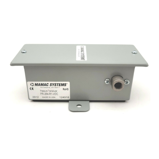
PRESSURE TRANSDUCER
INSTALLATION
Inspection
Inspect the package for damage. If damaged, notify the
appropriate carrier immediately. If undamaged, open the
package and inspect the device for obvious damage.
Return damaged products.
Requirements
• Tools (not provided)
- Digital Volt-ohm Meter (DVM)
- Appropriate screwdriver for mounting screws
- Appropriate drill and drill bit for mounting screws
• Appropriate accessories
• Two #8 self-tapping mounting screws (not provided)
• Training: Installer must be a qualified, experienced technician
Warning:
• Do not use on oxygen service, in an explosive/hazardous
environment, or with flammable/combustible media.
• Disconnect power supply before installation to prevent
electrical shock and equipment damage.
• Make all connections in accordance with the job wiring diagram
and in accordance with national and local electrical codes. Use
copper conductors only.
Caution:
• Use electrostatic discharge precautions (e.g., use of wrist
straps) during installation and wiring to prevent equipment
damage.
• Avoid locations where severe shock or vibration, excessive
moisture or corrosive fumes are present. NEMA Type 4
housings are intended for outdoor use primarily to provide
a degree of protection against wind-blown dust, rain, and
hose-directed water.
• Do not exceed ratings of the device.
Mounting
The PR-264 must be mounted on a vertical surface with the 1/8"
NPT connection pointed downward. Refer to Figure 7 for
mounting dimensions.
1. Remove the transducer cover using a Phillips head
screwdriver.
2. Select the mounting location.
3. Mount transducer on a vertical surface with two #8 self-tapping
screws (not provided).
4. Pull wires through bottom of enclosure and make necessary
connections.
5. Replace the unit cover and make pneumatic connections.
Wiring
Use maximum 12 AWG wire for wiring terminals. Use copper or
stainless steel tubing for the connection to the transducer. Refer
to Figures 1, 2, 3, & 4 for wiring information and Figures 5 & 6 for
switch designations.
(Wiring Instructions continued on pages 2 and 3.)
Model PR-264
Technical Information
TI.264-04
Advertisement

Subscribe to Our Youtube Channel
Related Manuals for MAMAC SYSTEMS PR-264


Summary of Contents for MAMAC SYSTEMS PR-264
- Page 1 *Includes non-linearity, hysteresis and non-repeatability ORDERING INFORMATION: PR-264- Mounting The PR-264 must be mounted on a vertical surface with the 1/8" NPT connection pointed downward. Refer to Figure 7 for mounting dimensions. 1. Remove the transducer cover using a Phillips head...
- Page 2 Caution: Caution: When multiple PR-264 units are powered from the same transformer, damage will result unless all 24G power leads are connected to the same power lead on all devices. It is mandatory that correct phasing be maintained when powering more than one device from a single transducer.
- Page 3 Page 3 of 4 Model PR-264 Technical Information TI.264-04 RoHS RoHS PRESSURE TRANSDUCER Range Configuration: Switch 1 (S1) R1 / R4 0–100 psig / 0–700 kPa (default) mA Output 0–50 psig / 0–350 kPa 0–25 psig / 0–175 kPa R2 / R5 0–300 psig / 0–2000 kPa (default)
- Page 4 1. Verify that the unit is mounted in the correct position. 2. Verify appropriate input signal and supply voltage. Figure 7 – PR-264 Pressure Transducer dimensions shown in inches and millimeters (mm). CAUTION: Never connect 120 VAC to these transducers.
Need help?
Do you have a question about the PR-264 and is the answer not in the manual?
Questions and answers