Panasonic GA-ML24TCPoE+ Installation Manual
Hide thumbs
Also See for GA-ML24TCPoE+:
- Installation manual (24 pages) ,
- Manual (496 pages) ,
- Manual (198 pages)
Table of Contents
Advertisement
Quick Links
Installation Guide
Thank you for purchasing our product.
This document provides important information about safe and proper
operations of this Ethernet Switch.
Please read the "Important Safety Instructions" on pages from 3 to 6.
Any problems or damages resulting from disassembly of this Ethernet
Switch by customers are not covered by the warranty.
The instruction manuals (Menu, Version, CLI Version
Web Version), latest firmware and SDN application
(ZEQUO assist Plus) can be downloaded from the following URL.
https://panasonic.co.jp/ew/pewnw/english/datadownload/index.html
Panasonic Electric Works Networks Co.,Ltd.
2-12-7, Higashi-Shimbashi, Minato-ku, Tokyo Japan, 105-0021
©
Panasonic Electric Works Networks Co.,Ltd. 2022
GA-ML24TCPoE+
PN262492-TH
Model No.
PN262492-MY
PN262492-ID
PN262492-SG
C0620-20222
Printed in Japan
Advertisement
Table of Contents

Related Manuals for Panasonic GA-ML24TCPoE+


Summary of Contents for Panasonic GA-ML24TCPoE+
- Page 1 Web Version), latest firmware and SDN application (ZEQUO assist Plus) can be downloaded from the following URL. https://panasonic.co.jp/ew/pewnw/english/datadownload/index.html Panasonic Electric Works Networks Co.,Ltd. 2-12-7, Higashi-Shimbashi, Minato-ku, Tokyo Japan, 105-0021 © Panasonic Electric Works Networks Co.,Ltd. 2022 C0620-20222 Printed in Japan...
-
Page 2: Table Of Contents
Contents Important Safety Instructions Basic Instructions for the Use of This Product 1 Product Outline 1.1 Features 1.2 Specifications 1.3 Accessories 1.4 Basic operation 2 Part Names and Functions 2.1 LED display change 2.2 PoE power supply function 3 Installation and Configuration 3.1 Grounding Cable Connection 3.2 Mounting to rack 3.3 Configuration of IP address (Basic) -
Page 3: Important Safety Instructions
Important Safety Instructions This chapter contains important safety instructions for preventing bodily injury and/or property damage. Please read carefully, and follow them at all times. Severity of bodily injury and/or property damage, which could result from incorrect use of the Ethernet Switch, are explained below. WARNING This symbol indicates a potential hazard that could result in serious injury or death. - Page 4 WARNING Do not put the Ethernet Switch into fire. Deviation could lead to explosion and/or fire. Do not connect the console ports with any other console cables except for our optional PN72001 RJ45-DSub 9-pin console cable. Deviation could lead to fire, electrical shock, and/or equipment failure. ...
- Page 5 CAUTION When using this Ethernet Switch to design systems, use it after applying appropriate measures such as setting up redundant configurations. Communication failures might be generated due to causes such as malfunctions or misoperations while the Ethernet Switch is being used. ...
- Page 6 Important Requests on Protection from Lightning Strike If you connect a network camera, a wireless access point, or other devices that can be affected by a lightning strike (in particular, devices installed outdoors) to the twisted pair port of this Ethernet Switch, a lightning surge current/voltage may be conducted to this Ethernet Switch through the twisted pair cable, leading to malfunction.
-
Page 7: Basic Instructions For The Use Of This Product
When Ethernet Switches mounting to rack, leave a minimum of 20 mm space between them. 1. Please note that Panasonic shall not bear any liability whatsoever for any damages (this shall include, but is not limited to, lost earnings, lost opportunities, etc.) -
Page 8: Product Outline
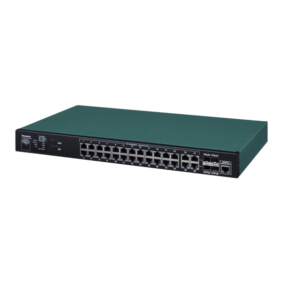
Product Outline GA-ML24TCPoE+ is an Ethernet Ethernet Switch with management function having 28ports of 10/100/1000BASE-T and SFP extension slot, one of which is selectable. Ports 1 to 24 support IEEE802.3at/af PoE power supply function. 1.1 Features Ports 1 to 24 are 10/100/1000BASE-T ports corresponding to auto negotiation. Also their speed and communication mode can be switched by configuration. -
Page 9: Specifications
1.2 Specifications Interface Twisted pair port 1-24: RJ45 connector (*1) Transmitting and receiving networks system IEEE802.3 10BASE-T IEEE802.3u 100BASE-TX IEEE802.3ab 1000BASE-T Twisted pair port 25-28: RJ45 connector Transmitting and receiving networks system IEEE802.3 10BASE-T IEEE802.3u 100BASE-TX IEEE802.3ab 1000BASE-T (*1) Energy Efficient Ethernet function IEEE802.3az(LPI) SFP extension slot 25 –... - Page 10 Product Outline Others STP/RSTP/MSTP Supports the IEEE802.1X authentication (MAC-based, port-based) MAC authentication, WEB authentication, Triple authentication, STEP authentication, IEEE802.1X supplicant, Port monitoring, Ring protocol, IGMP snooping, Loop detection/shutoff function, Storm control, DSCP mapping function, Login RADIUS function, DHCP client function, PoE scheduler function, PoE auto reboot function, Port grouping function, Multi-cast address group registration function Power supply...
-
Page 11: Accessories
When the terminal is not operating normally, for example when power is not supplied to the terminal, LED is not lighted. * For the configuration and management methods, please see the PDF version of the Operating Instructions on Panasonic’s website. -
Page 12: Part Names And Functions
Part Names and Functions Power cord hook block Power port AC100-240V Back panel Ground terminal MAC Address label 10/100/1000BASE-TX ports supporting PoE power supply SFP extension slot RIGHT LED(ORANGE):LOOP DETECTION SFP▲(25) SFP▲(27) ECO MODE ON・・・BLINK OFF・・・LIGHT GA-ML24TCPoE+ Front panel POWER STATUS/ECO CONSOLE LED DISPLAY... - Page 13 Status/ECO mode LED Power LED GIGA mode LED PoE LIM. LED DUPLEX mode LED Temperature sensor LED Fan sensor LED Loop History mode LED LED Display change button POWER LED (Power) Green Light : Power is ON. : Power is OFF. ...
- Page 14 Part Names and Functions Table1. Ports and Port LED lamps 1 to 28 correspond as shown below. Port LED Display mode Behavior Description Green Light Link is established. STATUS/ECO Green Blink Transmitting and receiving data. Orange Light It is shut off via the loop detection and shutoff function/storm control or the BPDU guard.
-
Page 15: Led Display Change
2.1 LED display change ●Display style set by the LED display change button Indication on the front panel and LED lamps RIGHT LED(ORANGE):LOOP DETECTION SFP▲(25) SFP▲(27) ECO MODE ON・・・BLINK OFF・・・LIGHT GA-ML24TCPoE+ POWER STATUS/ECO CONSOLE LED DISPLAY 9600.N.8.1(DTE) CHANGE BUTTON PoE LIM. GIGA KEEP PRESSING 3SEC ECO MODE ON/OFF... - Page 16 Part Names and Functions Switch two types of Base modes and their LEDs in the following way: When Base mode is Status mode (factory default setting) Press "LED DISPLAY CHANGE BUTTON" manually. Automatic Boot Automatically returns to Base mode after 1 minute. Status mode DUPLEX Loop History...
-
Page 17: Poe Power Supply Function
The priority settings for the power supply can be set and changed from the console, etc. * For the configuration and management methods, please see the PDF version of the Operating Instructions on Panasonic’s website. Power supply while the overload is caused by a single port When the power supply which is requested exceeds 30 W via a single port and the port LED (right) blinks in orange, and the power supply is stopped. -
Page 18: Installation And Configuration
Installation and Configuration 3.1 Grounding Cable Connection The chassis of the equipment must be grounded properly so that the lightning can flow to the ground, which improves the capability of the chassis for resisting the electromagnetic interference. 1. Ensure that the grounding cable is connected correctly so that the equipment is protected against lightning and interference. -
Page 19: Mounting To Rack
3.2 Mounting to rack Take out the provided mount brackets (2pcs.) and eight screws (for fixing the mount brackets and the Ethernet Switch).Fix the mount brackets to the four holes on each side of the Ethernet Switch using the screws. Then,securely install the Ethernet Switch on the rack using the four provided screws (for mounting on a 19-inch rack) or screws provided with the rack. -
Page 20: Configuration Of Ip Address (Basic)
Installation and Configuration 3.3 Configuration of IP address (Basic) (1) Connect this Ethernet Switch and PC with a RJ45–DSub 9-pin console cable and start up the terminal emulator (ZEQUO assist Plus, etc.). (2) Pressing Enter key once opens Login screen. Enter UserName and Password (the default is "manager"... - Page 21 Saving all configurations to NV-RAM..Done. GA-ML24TCPoE+# Screen 5 * For detailed configuration and management methods, and the settings from the ZEQUO assist Plus and the Web screens, please see the PDF version of the Operating Instructions on Panasonic’s website.
-
Page 22: Troubleshooting
Troubleshooting If you find any problem, please take the following steps to check. LED The POWER LED (Power) is not lit. Check if the power cord is disconnected. Please confirm that the power cord is securely connected to the power port. ... - Page 23 (the PoE LIM. LED is not blinking in orange). * For the configuration and management methods, please see the PDF version of the Operating Instructions on Panasonic’s website.
Need help?
Do you have a question about the GA-ML24TCPoE+ and is the answer not in the manual?
Questions and answers