Table of Contents
Advertisement
Quick Links
BOOSTER TYPE COMPUTER WEIGHER
CCW-R-2**B
INSTRUCTION MANUAL
•
Do not carry out installation, operation, service, or
maintenance until thoroughly understanding the
contents of this manual.
•
Keep this manual available at all times for installation,
operation, service, and maintenance.
UK PN: 281-5142
Issue 3: November 2008
Advertisement
Table of Contents

Subscribe to Our Youtube Channel
Related Manuals for ISHIDA CCW-R-2 B Series


Summary of Contents for ISHIDA CCW-R-2 B Series
- Page 1 UK PN: 281-5142 BOOSTER TYPE COMPUTER WEIGHER CCW-R-2**B INSTRUCTION MANUAL • Do not carry out installation, operation, service, or maintenance until thoroughly understanding the contents of this manual. • Keep this manual available at all times for installation, operation, service, and maintenance. Issue 3: November 2008...
- Page 2 For this reason, a commonly used OS is effective, and ISHIDA CO., LTD. use Windows XP Embedded. The following points need to be noted: 1. Do not copy or transfer (use on other devices) Windows XP Embedded.
- Page 3 2. Ishida Co., Ltd. holds the copyright of this manual and the copyright law protects all information contained herein. Any disclosure to third parties or unauthorized copying of the information contained herein is not permitted without prior written approval from Ishida Co., Ltd.
- Page 5 WARRANTY CONDITIONS WARRANTY CONDITIONS 1. Ishida Co., Ltd. only assumes responsibility for repairing or replacing components which are deemed to be defective due to improper materials or manufacturing. The measures to be taken for defects with uncertain cause shall be decided by mutual consultation between both parties.
- Page 6 1. Purpose of this manual This manual is designed to provide users with information about the operation, maintenance, inspection, and installation of the Ishida CCW-R series circular booster type computer weigher. 2. How to use this manual and how this manual is organized Chapters 1 through 4 contain basic information such as safety consideration, structure, and the operation of this device.
- Page 7 12.INSTALLATION • Installation conditions, To understand the appropriate • Maintenance engineers transportation and lifting, and installation environment, safe • Ishida service installation procedures transport and relocation of the engineers device, and secure installation procedures. 13 APPENDIX •...
- Page 8 OBJECTIVES AND ORGANIZATION OF THIS MANUAL 3.Illustrations and notations used in this manual 1. Illustrations of the equipment The illustrations used to describe the operation procedures are drawn in the most general shapes. The actual equipment may differ slightly from the illustrations.
-
Page 9: Table Of Contents
CCW-R-2**B INSTRUCTION MANUAL TABLE OF CONTENTS 1 SAFETY PRECAUTIONS Summary ........... 1-1 Warning Terms and Meaning . - Page 10 CCW-R-2**B INSTRUCTION MANUAL 3.3.2.2 Inputting Alphanumeric Characters and Symbols ....3-9 3.3.3 Correcting Confirmed Contents ........3-10 4 OPERATION PROCEDURES Summary.
- Page 11 CCW-R-2**B INSTRUCTION MANUAL Presetting the Double Weigher ........5-2 5.2.1 Registration Details.
- Page 12 CCW-R-2**B INSTRUCTION MANUAL 6.3.7 Help Function ..........6-30 [Main Menu] Screen .
- Page 13 CCW-R-2**B INSTRUCTION MANUAL 6.12.1 [Current Total] Screen ......... . 6-84 6.12.2 [X-bar Chart] Screen.
- Page 14 CCW-R-2**B INSTRUCTION MANUAL 6.15.5.1 [Active head] Tab Screen ........6-153 6.15.5.2 [AFD Setting] Tab Screen .
- Page 15 CCW-R-2**B INSTRUCTION MANUAL 8.3.3 Setting Procedures of Count Set Weighing ......8-16 8.3.4 [Select Display] Pop-up Menu (Count Set Weighing) ....8-18 8.3.5 Output During Count Set Production .
- Page 16 CCW-R-2**B INSTRUCTION MANUAL 10.3.7 Inspection of Rubber Cover (Annually)......10-16 10.3.8 Replacement of Memory Backup Battery ......10-17 10.3.9 Replacement of Fuses .
- Page 17 CCW-R-2**B INSTRUCTION MANUAL 12.4.6 Connecting TH Signal Wire ........12-11 12.4.7 Installing Timing Hopper .
- Page 18 CCW-R-2**B INSTRUCTION MANUAL 13.6.1.2 FDRV Board (P-5578*) ........13-17 13.6.1.3 FDC Board (P-5532*) .
- Page 19 CCW-R-2**B INSTRUCTION MANUAL 13.19.2 WCU Board (P-5561*) ......... 13-49 13.19.3 DMU Board (P-5562*).
- Page 20 CCW-R-2**B INSTRUCTION MANUAL...
-
Page 21: Safety Precautions
• When there are any questions or when anything is unclear, contact the distributor or Ishida customer support staff. Do not proceed with any operations until the required instructions are given. <Contents>... -
Page 22: Warning Terms And Meaning
1 SAFETY PRECAUTIONS CCW-R-2**B INSTRUCTION MANUAL Warning Terms and Meaning In case the warning indications shown in the instruction manual and the warning labels attached on the device unit are not followed, degree of danger (or scale of accidents) is divided into the following three levels. -
Page 23: General Precautions
CCW-R-2**B INSTRUCTION MANUAL 1 SAFETY PRECAUTIONS General Precautions This section describes the general precautions, which need to be observed for safe device operations. DANGER When working on the device with the main body cover open, do not touch the current-carrying parts. Failure to do so may cause an electrical shock. - Page 24 1 SAFETY PRECAUTIONS CCW-R-2**B INSTRUCTION MANUAL CAUTION Do not operate the operation panel of the remote control unit using a pointed object such as a ball point pen or mechanical pencil. A pointed object may damage the operation panel. Use fingers to press the operation panel of the remote control unit.
-
Page 25: Special Precautions
CCW-R-2**B INSTRUCTION MANUAL 1 SAFETY PRECAUTIONS Special Precautions This section describes the precautions which need to be observed for safe operation, specifically for this device. Follow the special precautions below along with the general precautions. WARNING When cleaning the device, the operator must turn OFF and lock the main power switch and keep the key in his possession during the work. -
Page 26: Warning Label
Clean the warning labels using a cloth, water, and neutral detergent. Do not use organic solvents or gasoline. If the warning labels are damaged, lost, or illegible, replace the labels. Check the machine type (model) and machine identification, and contact the distributor or Ishida customer support. 1.5.2 Attached Locations of Warning Labels The locations of attached warning labels are shown in Figure 1-1 Attached Locations of Warning Labels. -
Page 27: Power Supply Shut Off And Indication
CCW-R-2**B INSTRUCTION MANUAL 1 SAFETY PRECAUTIONS Power Supply Shut Off and Indication This section describes the power supply shut off and its indication. • Before performing maintenance and inspections, shut off the power supply in order to secure operator safety. •... - Page 28 1 SAFETY PRECAUTIONS CCW-R-2**B INSTRUCTION MANUAL...
-
Page 29: Introduction
The device can be used as a weighing instrument for a wide range of products from food such as snacks and candies to machine parts. *1 *1 Application should be limited to products approved by Ishida Co., Ltd. for design reasons. -
Page 30: Features Of The Device
2 INTRODUCTION CCW-R-2**B INSTRUCTION MANUAL Features of the Device The device consists of two computer weighers, which can be used as follows: < Use as a double weigher (Use as two weighers)> 1. The device can be divided into two weighers and weigh two different products simultaneously. Example: Weigh 100g of potato chips on one weigher and 80g of corn snack on the other. -
Page 31: Specifications Of The Device
CCW-R-2**B INSTRUCTION MANUAL 2 INTRODUCTION • It is also possible to use the device as a double mix weigher by setting the device as a double weigher and dividing each weigher into two sections. Specifications of the Device This section describes the specifications of the device. Understand the details of this section thoroughly before operating the device. -
Page 32: Term Description
2 INTRODUCTION CCW-R-2**B INSTRUCTION MANUAL Term Description The following specific terms are used in this instruction manual. Table 2-1Term Descriptions Term Description Products The products weighed with this device. Infeeder A front-end device that supplies products to this device. Packer A post-process device that packages products after being weighed by this device. - Page 33 CCW-R-2**B INSTRUCTION MANUAL 2 INTRODUCTION Table 2-1Term Descriptions (Continued) Term Description Master mode A mode in which, when this device is interlocked with the packer, it discharges upon receiving a (continuous) signal from the packer. Slave mode A mode in which, when this device is interlocked with the packer, it discharges upon receiving a one shot signal from the packer.
-
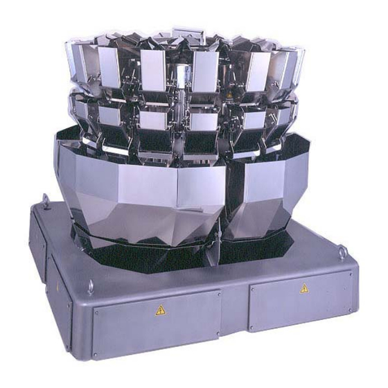
Page 34: Components Of The Device
2 INTRODUCTION CCW-R-2**B INSTRUCTION MANUAL Components of the Device This section describes the component names and functions of the device. WP Specification Fig.2-1 Device Overview Table 2-2 Descriptions of Components Name Function and Description Inlet chute A product feeding inlet. (Optional) This collects the products supplied from the infeeder to the center of the dispersion table. - Page 35 CCW-R-2**B INSTRUCTION MANUAL 2 INTRODUCTION Table 2-2 Descriptions of Components (Continued) Name Function and Description Timing hopper (TH) Temporarily pools products passed through the discharge chute and discharges them in (Optional) accordance with the request from the following processing device such as the packer. Timing hopper drive unit Activates open/close of the timing hopper.
-
Page 36: Operation Outline
2 INTRODUCTION CCW-R-2**B INSTRUCTION MANUAL Operation Outline This section describes the operation outline from weighing and combining the product supplied to the inlet chute to discharging from the timing hopper. Product flow outline Fig.2-2 Operation Outline 1. The product from the infeeder is supplied to the inlet chute. 2. -
Page 37: Operating Panels
CCW-R-2**B INSTRUCTION MANUAL 3 OPERATING PANELS OPERATING PANELS Summary This chapter describes the remote control unit components and functions required for the device operations, and the basic operation method and display descriptions of the operation panel. • Thoroughly understand the contents of this chapter before operating the device. -
Page 38: Items And Functions Of Remote Control Unit
3 OPERATING PANELS CCW-R-2**B INSTRUCTION MANUAL Items and Functions of Remote Control Unit This section describes the component names and functions of the remote control unit, using the figure below. Fig.3-1 Remote Control Unit Overview Table 3-1 Descriptions of Remote Control Unit Functions Name Function Operation Panel... -
Page 39: Operation Panel And Data Input
CCW-R-2**B INSTRUCTION MANUAL 3 OPERATING PANELS Operation Panel and Data Input The device is operated with the operation panel screens. The operation panel is a touch screen. • Use fingers to press the operation panel. Using a pointed object such as a ball point pen may damage the operation panel. - Page 40 3 OPERATING PANELS CCW-R-2**B INSTRUCTION MANUAL • The screen display above is an example. Menu keys and display areas differ depending on each menu and operation level. <Menu keys> The operation keys include the following along with the standard keys. Table 3-3 Types and Display Examples of the Main Operation Keys Key Type Display Example...
- Page 41 CCW-R-2**B INSTRUCTION MANUAL 3 OPERATING PANELS <Page display keys> When the operation screen extends to multiple pages, switch the pages by using the following operation keys. Table 3-4 Display Examples of Page Selection Keys Key Type Display Example Function Index Displayed on the right side of the screen for the items such as preset.
- Page 42 3 OPERATING PANELS CCW-R-2**B INSTRUCTION MANUAL <Hierarchic structure of the screen> The screens with multiple pages have the following hierarchic structure. Fig.3-4 Overview (1) Key A belongs to the tab B screen. Tab B as well as the other displayed tabs, and key C, belong to screen D. Therefore, the key C function applies to tab B and all other tab screens displayed.
-
Page 43: Data Input
CCW-R-2**B INSTRUCTION MANUAL 3 OPERATING PANELS 3.3.2 Data Input When inputting figures and product names, use the [Numeric Keypad] screen and [Keyboard] screen. The [Numeric Keypad] screen and [Keyboard] screen are displayed when data input is required. Use the [Numeric Keypad] screen to input figures and the [Keyboard] screen to input alphanumeric characters. -
Page 44: Inputting Figures
3 OPERATING PANELS CCW-R-2**B INSTRUCTION MANUAL 3.3.2.1 Inputting Figures When inputting figures, the [Numeric Keypad] screen will be displayed. Fig.3-6 [Numeric Keypad] Screen Table 3-6 Descriptions of [Numeric Keypad] Screen Functions Name Function Set item display area Displays the current input item. Input display area Displays the input figures. -
Page 45: Inputting Alphanumeric Characters And Symbols
CCW-R-2**B INSTRUCTION MANUAL 3 OPERATING PANELS 3.3.2.2 Inputting Alphanumeric Characters and Symbols When the alphanumeric characters and symbols are input, the [Keyboard] screen will be displayed. <Keyboard> Fig.3-7 [Keyboard] Screen Table 3-7 Descriptions of [Keyboard] Screen Functions Name Function Set item display area Displays the current set item. -
Page 46: Correcting Confirmed Contents
3 OPERATING PANELS CCW-R-2**B INSTRUCTION MANUAL Table 3-7 Descriptions of [Keyboard] Screen Functions (Continued) Name Function [CANCEL] key Cancels the input from the keyboard. When pressed, the display returns to the previous screen without any input. For setting using the [Keyboard] screen, follow the procedures below. 1. -
Page 47: Operation Procedures
B CCW-R-2** INSTRUCTION MANUAL 4 OPERATION PROCEDURES OPERATION PROCEDURES Summary This chapter describes emergency stop procedures, production outline, production procedures, and each operation during production. • Thoroughly understand the contents of “3 OPERATING PANELS” before operating the device. <Contents> • Outline of the production, preparation work, and actual procedures •... -
Page 48: Emergency Stop And Restart
B 4 OPERATION PROCEDURES CCW-R-2** INSTRUCTION MANUAL Emergency Stop and Restart Perform the following procedures when stopping the device in the event of an emergency and then restarting it. Emergency stop procedures 1. Turn OFF the main power switch on the side of the remote control unit. -
Page 49: Outline Of The Production
B CCW-R-2** INSTRUCTION MANUAL 4 OPERATION PROCEDURES Outline of the Production This section describes the outline of the production. Refer to “4.4 Production Procedures” and the subsequent sections for details regarding production procedures. 4.4.1 Pre-start Inspection ↓ ↓ ↓ 4.4.2 Air Pressure Adjustment (WP specification) ↓... -
Page 50: Production Procedures
B 4 OPERATION PROCEDURES CCW-R-2** INSTRUCTION MANUAL Production Procedures This section describes the production procedures. 4.4.1 Pre-start Inspection • For maintenance and inspections, unless instructed, the operator must turn OFF and lock the main power switch, and keep the key in his possession during the work. -
Page 51: Air Pressure Adjustment (Wp Specification)
B CCW-R-2** INSTRUCTION MANUAL 4 OPERATION PROCEDURES 4.4.2 Air Pressure Adjustment (WP specification) 1. Shut the air supply cockstop to stop the compressed air supply. Cockstop 2. Turn the drain to let the remaining air out of the air dryer. Drain Fig.4-4 Air Pressure Adjustment (1) 3. -
Page 52: Turning The Device Power Switch On
B 4 OPERATION PROCEDURES CCW-R-2** INSTRUCTION MANUAL 4.4.3 Turning the Device Power Switch ON • Turn the main power switch ON at least 30 minutes before starting the production in order to get stable weighing results. This section describes how to supply power to the device. 1. -
Page 53: Selecting The Machine Mode
B CCW-R-2** INSTRUCTION MANUAL 4 OPERATION PROCEDURES 4.4.5 Selecting the Machine Mode Select the machine mode (double weighing or mix weighing) before operating the weigher. 1. Press the [CH.Select] pop-up key The [CH.Select] pop-up menu appears. Fig.4-9 [Main Menu] Screen 2. - Page 54 B 4 OPERATION PROCEDURES CCW-R-2** INSTRUCTION MANUAL • The [Main Menu] screen will differ depending on the channel for the operation. In this manual, screenshots for double weighing are used for all descriptions. When using the start-up assistant function, go to “4.4.6 Start-up Assistant Function”.
-
Page 55: Start-Up Assistant Function
B CCW-R-2** INSTRUCTION MANUAL 4 OPERATION PROCEDURES 4.4.6 Start-up Assistant Function The start-up assistant function guides you through the steps up to the production and simplifies them by following the instructions on the screen. When not using the start-up assistant function, please proceed to “4.4.7 Preset Selection”. 1. - Page 56 B 4 OPERATION PROCEDURES CCW-R-2** INSTRUCTION MANUAL 6. Scroll the screen by using the scroll key or the scroll bar until the desired preset item is displayed. 7. Press the [Preset Item] key to select the item. 8. Press the [OK] key The [WH Zero Adjustment Start] screen of the start-up assistant menu appears.
- Page 57 B CCW-R-2** INSTRUCTION MANUAL 4 OPERATION PROCEDURES • On the [DF Zero Adjustment] screen, the dispersion table is displayed in blue. When the dispersion table is displayed in red immediately after power-on, it is not possible to proceed to the next step until the zero adjustment is performed.
-
Page 58: Preset Selection
B 4 OPERATION PROCEDURES CCW-R-2** INSTRUCTION MANUAL • The start-up assistant function ends when the production starts and the normal operation menu appears. • The start-up assistant function covers the steps up to “4.4.9 Starting the Production”. • The start-up assistant function is available at any time, but the appearance of the screen differs depending on the machine condition just before activating the function. - Page 59 B CCW-R-2** INSTRUCTION MANUAL 4 OPERATION PROCEDURES 2. Use the scroll key or the scroll bar and press the desired [Preset Item]. • When using both C1 and C2 in the double weighing, select the preset item for each channel. 3.
- Page 60 B 4 OPERATION PROCEDURES CCW-R-2** INSTRUCTION MANUAL <Switching the display for the [Select Preset] screen> There are two display modes in the [Select Preset] screen: the photo mode and the list mode. In the photo mode, you can select the product visually; in the list mode, you can sort the items by product category, weight, etc.
- Page 61 B CCW-R-2** INSTRUCTION MANUAL 4 OPERATION PROCEDURES <Selecting the preset number directly> The preset number can be directly selected using the [Numeric Keypad] screen. This function is useful when the preset number is already identified and the number is too large to find by scrolling through the screen.
-
Page 62: Zero Adjustment
B 4 OPERATION PROCEDURES CCW-R-2** INSTRUCTION MANUAL 4.4.8 Zero Adjustment Perform zero adjustment for the weigh hopper and dispersion table in order to weigh the product precisely. <Zero adjustment for the weigh hopper> 1. Press the [Zero Adjst] key The [Zero Adjustment] screen appears. All hoppers are selected and displayed in blue. - Page 63 B CCW-R-2** INSTRUCTION MANUAL 4 OPERATION PROCEDURES When zero adjustment operation finishes, each [WH] key displays the respective weight. 3. Make sure that each weight display of the [WH] key is within 0.0±0.1g. • If the weight display reading exceeds 0.1g or falls below -0.1g, perform the zero adjustment again.
- Page 64 B 4 OPERATION PROCEDURES CCW-R-2** INSTRUCTION MANUAL <Zero adjustment for the dispersion table> 1. In the [Zero Adjustment] screen, press the [Slct All DF] key All dispersion tables are displayed in blue. 2. Make sure that there is no product on the dispersion table.
- Page 65 B CCW-R-2** INSTRUCTION MANUAL 4 OPERATION PROCEDURES When zero adjustment operation finishes, each [DF] key displays the respective weight. 4. Make sure that each weight display of the [DF] key is 0g. • When the weight display reading exceeds 0g or falls below 0g, perform the zero adjustment again.
-
Page 66: Starting The Production
B 4 OPERATION PROCEDURES CCW-R-2** INSTRUCTION MANUAL 4.4.9 Starting the Production Start the production. 1. Press the [Start] key The production starts and the [Production] screen appears. • When the feeder is interlocked with this device to automatically supply the product, pressing the [Infeed Control] key to ON will start the product supply. -
Page 67: Stopping The Production
B CCW-R-2** INSTRUCTION MANUAL 4 OPERATION PROCEDURES 4.4.10 Stopping the Production Stop the production. 1. When the infeed control is on, press the [Infeed Control] key The lamp of the [Infeed Control] key turns off and the product supply to the device is terminated. -
Page 68: Discharging The Products
B 4 OPERATION PROCEDURES CCW-R-2** INSTRUCTION MANUAL 4.4.11 Discharging the Products Discharge the remaining products from the device. <Discharging the products> 1. Press the [Drain] key The [Drain] screen appears. Discharging of the product starts. Fig.4-40 [Main Menu] Screen 2. After discharging all products, press the [Drain STOP] key Discharging is terminated. -
Page 69: Turning The Device Power Switch Off
B CCW-R-2** INSTRUCTION MANUAL 4 OPERATION PROCEDURES 4.4.12 Turning the Device Power Switch OFF Shut off the power supplied to the device. 1. Press the [Power] key The control system power supply is turned OFF. Fig.4-43 [Main Menu] Screen 2. Turn the main power switch OFF. The display of the control panel disappears. -
Page 70: Display During The Operation
B 4 OPERATION PROCEDURES CCW-R-2** INSTRUCTION MANUAL Display During the Operation The screen display during the operation can be switched by selecting a tab from the following: Combination, Feeder Adjust, Timing Adjust, Total Data, and Weight Display. ( 6.7 [Production] Screen) In the [Combination] screen, the display can be switched between the combination display and the expansion display, by using the [Select Display] pop-up key. -
Page 71: Combination] Screen
B CCW-R-2** INSTRUCTION MANUAL 4 OPERATION PROCEDURES 4.5.1 [Combination] Screen To display the [Combination] screen, press the [Combination] tab on the [Production] screen. Fig.4-45 [Combination] Screen ([Production] Screen, Double Weigher) Fig.4-46 [Combination] Screen ([Production] Screen, Mix Weigher) 4-25... - Page 72 B 4 OPERATION PROCEDURES CCW-R-2** INSTRUCTION MANUAL Table 4-1 Items and Functions of [Combination] Screen Name Function Combination weight display The combined weight value is displayed on each channel. The lamp indication varies depending on the results. Green lamp: Proper weight Yellow lamp: Over weight Red lamp: Under weight Head condition display...
-
Page 73: Select Display] Pop-Up Menu In [Combination] Screen
B CCW-R-2** INSTRUCTION MANUAL 4 OPERATION PROCEDURES 4.5.1.1 [Select Display] Pop-up Menu in [Combination] Screen On the [Combination] screen, either the [Combination] or [Expansion Display] mode can be selected. Press the [Select Display] pop-up key on the [Combination] screen, and select the desired display mode. Fig.4-47 [Select Display] Pop-up Menu ([Combination] Screen) Table 4-2 [Select Display] Pop-up Menu and Functions of the [Combination] Screen Name... - Page 74 B 4 OPERATION PROCEDURES CCW-R-2** INSTRUCTION MANUAL Table 4-2 [Select Display] Pop-up Menu and Functions of the [Combination] Screen(Continued) Name Function [Expansion Display] key Selects the [Expansion Display] screen for the combination weight. Fig.4-49 [Expansion Display] Screen 4-28...
-
Page 75: Temporary Stop And Restart
B CCW-R-2** INSTRUCTION MANUAL 4 OPERATION PROCEDURES Temporary Stop and Restart To temporarily stop the production and then restart it, follow the procedures below. 4.6.1 Temporary Stopping Stop the production temporarily. 1. Press the [Stop] key The [Stop] key is greyed out and the [Start] key appears. -
Page 76: Outputting The Operational Status
B 4 OPERATION PROCEDURES CCW-R-2** INSTRUCTION MANUAL Outputting the Operational Status During the operation, every combination result or current total result can be output as necessary. 4.7.1 Every Combination Output • Every combination output can be set by the site engineer or higher level personnel. This setting outputs the combination weight value during the production. - Page 77 B CCW-R-2** INSTRUCTION MANUAL 4 OPERATION PROCEDURES 3. Press the [Total Setting] key The [Total Setting] screen appears. Fig.4-54 [Select Total] Pop-up Menu ([Production] Screen) 4. Select [C1] or [C2] for the [Every Combination Output] option. • With this setting, the results are output in every two weighings of the selected channel.
-
Page 78: Current Total Output
B 4 OPERATION PROCEDURES CCW-R-2** INSTRUCTION MANUAL 4.7.2 Current Total Output This setting outputs the total data of the currently selected product to a printer or as a file. To perform the current total output, follow the procedures below. • Printing or file output can be set by the [Installation] or higher level personnel via the [Destination ID] Tab Screen of the [Control Panel] screen. - Page 79 B CCW-R-2** INSTRUCTION MANUAL 4 OPERATION PROCEDURES Fig.4-58 Current Total Output (Example) Table 4-3 Output Details Name Remarks Product code — Product name — Proper weight Number of times that the proper discharge is performed. Target weight — Total value Total discharged weight.
-
Page 80: Loading The Printer Paper
B 4 OPERATION PROCEDURES CCW-R-2** INSTRUCTION MANUAL Loading the Printer Paper When the message “No Paper” is displayed on the lower part of the screen, follow the procedures below to load the printer paper. 1. Slide the printer cover retainer to open the cover. - Page 81 B CCW-R-2** INSTRUCTION MANUAL 4 OPERATION PROCEDURES 4. Press and open the clips to remove the remaining roll core. 5. Align the roll as shown in the figure and push CLIPS onto the clips. Fig.4-63 Roll Paper Installation 6. Insert the end of the roll paper into the printer. 7.
-
Page 82: Handling Drive Unit
B 4 OPERATION PROCEDURES CCW-R-2** INSTRUCTION MANUAL Handling Drive Unit This section describes how to handle the drive unit. • DO NOT, UNDER ANY CIRCUMSTANCES, CLOSE THE HOPPERS WITH HANDS OR TOOLS AS SHOWN IN THE FIGURE. Doing so may damage the drive unit. -
Page 83: Registering Of Products
CCW-R-2**B INSTRUCTION MANUAL 5 REGISTERING OF PRODUCTS REGISTERING OF PRODUCTS Summary This chapter describes the outline and procedures for registering a new product. • Read and thoroughly understand Chapter 1 through to Chapter 4 before registering the product. <Contents> Setting screens by product <Purpose>... -
Page 84: Presetting The Double Weigher
5 REGISTERING OF PRODUCTS CCW-R-2**B INSTRUCTION MANUAL Presetting the Double Weigher This section describes the preset procedures when this device is used as a double weigher. 5.2.1 Registration Details Items and details to be set in the preset screen are described in “Table 5-1 Preset Details”. •... - Page 85 CCW-R-2**B INSTRUCTION MANUAL 5 REGISTERING OF PRODUCTS Table 5-1 Preset Details (Continued) Setting Item Setting Detail Initial Value Setting Example Interlock Parameter Selects the interlock mode between the Number device and the packer. There are four different interlock modes. Section Parameter Selects the section division pattern when Number dividing weigh heads into sections and...
- Page 86 5 REGISTERING OF PRODUCTS CCW-R-2**B INSTRUCTION MANUAL Table 5-1 Preset Details (Continued) Setting Item Setting Detail Initial Value Setting Example Upper Weight Limit Sets the upper limit of the proper weight. Lower Weight Limit Sets the lower limit of the proper weight in grams when the average control function is utilized.
-
Page 87: Outline Of The Registration
CCW-R-2**B INSTRUCTION MANUAL 5 REGISTERING OF PRODUCTS 5.2.2 Outline of the Registration This section describes the outline of the product registration for the double weigher. Refer to the next section for details regarding the operation procedures. Items for C1 and C2 should be registered respectively for the double weigher. For items marked with * in the following chart, respective initial values are registered. -
Page 88: Preset Procedures
5 REGISTERING OF PRODUCTS CCW-R-2**B INSTRUCTION MANUAL 5.2.3 Preset Procedures This section describes the registration procedures using the example shown in “5.2.1 Registration Details”. Numerical values shown in parentheses are taken from setting examples in “Table 5-1 Preset Details”. The preset procedure is performed by the Site Engineer level or the Installation level personnel. Refer to “6.3.4 Operation Level Selection”... -
Page 89: Setting The Product
CCW-R-2**B INSTRUCTION MANUAL 5 REGISTERING OF PRODUCTS 5.2.3.2 Setting the Product <Purpose> To set the product name, product code, and product category of the product to be weighed with this device. 1. Press the [Preset] key for C1. The [Product] screen of the [Preset] screen for C1 appears. - Page 90 5 REGISTERING OF PRODUCTS CCW-R-2**B INSTRUCTION MANUAL 4. Press the [Product Code] key The [Keyboard] screen appears. Fig.5-6 [Product] Tab Screen ([Preset] Screen) 5. Set the product code. (01) The [Keyboard] screen disappears. Fig.5-7 [Keyboard] Screen ([Preset] Screen) 6. Press the [Product Category] key The [Keyboard] screen appears.
- Page 91 CCW-R-2**B INSTRUCTION MANUAL 5 REGISTERING OF PRODUCTS 7. Set the product category. (A100) The [Keyboard] screen disappears. Fig.5-9 [Keyboard] Screen ([Preset] Screen) <Selecting the photo> 1. Press the [Photo Selection] drop-down key The [Photo Selection] drop-down list appears. Fig.5-10 [Product] Tab Screen ([Preset] Screen) 2.
-
Page 92: Setting The Speed
5 REGISTERING OF PRODUCTS CCW-R-2**B INSTRUCTION MANUAL 5.2.3.3 Setting the Speed <Purpose> To set the number of packs to be discharged from the device per minute. Discharge count, average control, interlock parameter number, and sectioning set can be specified when necessary. -
Page 93: Setting The Weight Value
CCW-R-2**B INSTRUCTION MANUAL 5 REGISTERING OF PRODUCTS 5.2.3.4 Setting the Weight Value <Purpose> To set the weight value and permissible weight value weighed with this device. 1. Press the [Weight Setting] key in the index. The [Weight Setting] screen appears. Fig.5-15 [Machine] Tab Screen ([Preset] Screen) 2. - Page 94 5 REGISTERING OF PRODUCTS CCW-R-2**B INSTRUCTION MANUAL 4. Press the [Upper Weight Limit] key The [Numeric Keypad] screen appears. Fig.5-18 [Weight Setting] Index Screen ([Preset] Screen) 5. Set the upper weight limit. (3) The [Numeric Keypad] screen disappears. Fig.5-19 [Numeric Keypad] Screen ([Preset] Screen) 5-12...
-
Page 95: Presetting Other Channels
CCW-R-2**B INSTRUCTION MANUAL 5 REGISTERING OF PRODUCTS 5.2.3.5 Presetting Other Channels Preset other channels. 1. Press the [Exit] key The [Main Menu] screen appears. Fig.5-20 [Weight Setting] Index Screen ([Preset] Screen) • When the preset number is changed in the [Preset] screen, press the [Exit] key to show the confirmation screen. -
Page 96: Presetting The Mix Weigher
5 REGISTERING OF PRODUCTS CCW-R-2**B INSTRUCTION MANUAL Presetting the Mix Weigher This section describes the preset procedures when this device is used as a mix weigher. 5.3.1 Registration Details Items and details to be set in the preset screen are described in “Table 5-2 Preset Details”. •... - Page 97 CCW-R-2**B INSTRUCTION MANUAL 5 REGISTERING OF PRODUCTS Table 5-2 Preset Details (Continued) Setting Item Setting Detail Initial Value Setting Example Speed Sets the number of packs to be discharged from the device per minute. Dump Count Divides and discharges the product separately to prevent the product from jamming in the packer when the target weight is large or when a product will...
- Page 98 5 REGISTERING OF PRODUCTS CCW-R-2**B INSTRUCTION MANUAL Table 5-2 Preset Details (Continued) Setting Item Setting Detail Initial Value Setting Example Timing Adjustment Sets the timing value for the opening/closing • WH-DS: 0 • WH-DS: 0 of each hopper. • IS-WH: 0 •...
-
Page 99: Outline Of The Registration
CCW-R-2**B INSTRUCTION MANUAL 5 REGISTERING OF PRODUCTS 5.3.2 Outline of the Registration This section describes the outline of the product registration for the mix weigher. Refer to “5.3.3 Preset Procedures” for details regarding the operation procedures. For the mix weigher, there are some setting items that apply to the whole mix weigher, and some that apply to each section. -
Page 100: Preset Procedures
5 REGISTERING OF PRODUCTS CCW-R-2**B INSTRUCTION MANUAL 5.3.3 Preset Procedures This section describes the registration procedures using the example shown in “5.3.1 Registration Details”. Numerical values shown in parentheses are taken from descriptions in “Table 5-2 Preset Details”. The preset procedure is performed by the [Site Engineer] level or the [Installation] level personnel. •... -
Page 101: Selecting The Section
CCW-R-2**B INSTRUCTION MANUAL 5 REGISTERING OF PRODUCTS 5.3.3.2 Selecting the Section <Purpose> To switch to the desired section and select the sectioning mode as required. <Procedures for selecting the section parameter number> 1. Press the [Preset] key The [Preset] screen appears. Fig.5-25 [Main Menu] Screen 2. - Page 102 5 REGISTERING OF PRODUCTS CCW-R-2**B INSTRUCTION MANUAL 4. Select the section parameter number according to the product. Select a valid number from 1 to 8 as the section parameter number. 5. Press the [Exit] key The [Section Parameter Number] screen disappears.
- Page 103 CCW-R-2**B INSTRUCTION MANUAL 5 REGISTERING OF PRODUCTS <Section switching procedures> • Section switching is available in the [Item], [Product Setting] and [Weight Setting] screens. 1. Press the [Section Select] drop-down key. The [Section Select] drop-down list appears. Fig.5-29 [Product Setting] Index Screen ([Preset] Screen) 2.
-
Page 104: Setting The Product
5 REGISTERING OF PRODUCTS CCW-R-2**B INSTRUCTION MANUAL 5.3.3.3 Setting the Product <Purpose> To set the product name, product code, and product category of the product to be weighed with this device. The term “product” here refers to products made by mixing the weighed goods according to the section setting. - Page 105 CCW-R-2**B INSTRUCTION MANUAL 5 REGISTERING OF PRODUCTS 3. Set the product name. (MIX CANDY) The [Preset] screen appears. • After changing the settings, the [Cancel] key becomes operable. To cancel the settings, press the [Cancel] key. To accept the settings, press the [Exit] key Fig.5-34 [Keyboard] Screen ([Preset] Screen) 4.
- Page 106 5 REGISTERING OF PRODUCTS CCW-R-2**B INSTRUCTION MANUAL 6. Press the [Product Category] key The [Keyboard] screen appears. Fig.5-37 [Product] Tab Screen ([Preset] Screen) 7. Set the product category. (C200) The [Keyboard] screen disappears. Fig.5-38 [Keyboard] Screen ([Preset] Screen) • Procedures to display the product photos are the same as those described in “Selecting the photo” of “5.2.3.2 Setting the Product”...
-
Page 107: Setting The Weighed Product
CCW-R-2**B INSTRUCTION MANUAL 5 REGISTERING OF PRODUCTS 5.3.3.4 Setting the Weighed Product The term “weighed product” here refers to the individual weighed goods that compose the product. • When there is only one section, the [Section Select] drop-down key and the [Product Setting] index are not displayed on the screen. - Page 108 5 REGISTERING OF PRODUCTS CCW-R-2**B INSTRUCTION MANUAL 3. Set the product name. (S1: CANDY A, S2: CANDY B) The [Keyboard] screen disappears. Perform the settings for the other section by selecting the section from the [Section Select] drop-down key. Fig.5-41 [Keyboard] Screen ([Preset] Screen) 4.
- Page 109 CCW-R-2**B INSTRUCTION MANUAL 5 REGISTERING OF PRODUCTS 6. Select [CNSC TPG] or [Off] for the [Mix Topping Method] option. (S1: [CNSC TPG], S2: [Off]) Fig.5-44 [Product Setting] Index Screen ([Preset] Screen) 5-27...
-
Page 110: Setting The Weight Value
5 REGISTERING OF PRODUCTS CCW-R-2**B INSTRUCTION MANUAL 5.3.3.5 Setting the Weight Value <Purpose> To set the weight value and permissible weight value weighed with this device for each section. 1. Press the [Weight Setting] key in the index. The [Weight Setting] screen appears. Fig.5-45 [Product Setting] Index Screen ([Preset] Screen) 2. -
Page 111: Completing Preset Procedures
CCW-R-2**B INSTRUCTION MANUAL 5 REGISTERING OF PRODUCTS 4. Press the [Upper Weight Limit] key The [Numeric Keypad] screen appears. Fig.5-48 [Weight Setting] Index Screen ([Preset] Screen) 5. Set the upper weight limit. (S1: 5, S2: 5) The [Numeric Keypad] screen disappears. Fig.5-49 [Numeric Keypad] Screen ([Preset] Screen) 5.3.3.6... -
Page 112: Preset Management
5 REGISTERING OF PRODUCTS CCW-R-2**B INSTRUCTION MANUAL Preset Management When pressing the [Exit] key after completing the preset procedures, the preset information is automatically saved to the main body memory. Preset information saved in a certain preset number can be copied to another preset number. Detailed preset information can be copied to the memory card in order to maintain backup data or to accept more preset settings. -
Page 113: Functions Of The Operation Screens
CCW-R-2**B INSTRUCTION MANUAL 6 FUNCTIONS OF THE OPERATION SCREENS FUNCTIONS OF THE OPERATION SCREENS Summary This chapter describes the functions of the [Operation] screen required for production. The keys displayed in each operation screen include the keys to call functions directly, the keys to input and set numerical values and alphabets with the [Numeric Keypad] screen or [Keyboard] screen, the keys to select items from pop-up keys, drop-down keys or radio buttons, and the keys to switch screens or display modes. -
Page 114: Operation Keys And Operation Levels
6 FUNCTIONS OF THE OPERATION SCREENS CCW-R-2**B INSTRUCTION MANUAL Operation Keys and Operation Levels The operable levels for each operation key are as follows: • Some of the keys in the list may not appear depending on the machine status or specifications set by the user. - Page 115 CCW-R-2**B INSTRUCTION MANUAL 6 FUNCTIONS OF THE OPERATION SCREENS...
- Page 116 6 FUNCTIONS OF THE OPERATION SCREENS CCW-R-2**B INSTRUCTION MANUAL...
- Page 117 CCW-R-2**B INSTRUCTION MANUAL 6 FUNCTIONS OF THE OPERATION SCREENS...
- Page 118 6 FUNCTIONS OF THE OPERATION SCREENS CCW-R-2**B INSTRUCTION MANUAL...
- Page 119 CCW-R-2**B INSTRUCTION MANUAL 6 FUNCTIONS OF THE OPERATION SCREENS...
- Page 120 6 FUNCTIONS OF THE OPERATION SCREENS CCW-R-2**B INSTRUCTION MANUAL...
-
Page 121: Upper Setting Bar
CCW-R-2**B INSTRUCTION MANUAL 6 FUNCTIONS OF THE OPERATION SCREENS Upper Setting Bar The upper setting bar is constantly displayed at the top of each screen and can be used to set the basic operational environment. Fig.6-1 Upper Setting Bar (e.g. [Main Menu] Screen) Table 6-1 Items and Functions of Upper Setting Bar Name Function... - Page 122 6 FUNCTIONS OF THE OPERATION SCREENS CCW-R-2**B INSTRUCTION MANUAL Table 6-1 Items and Functions of Upper Setting Bar(Continued) Name Function [Help] key Displays the descriptions for each key. The [Help] key blinks when pressed. If a desired key is pressed after that, the function details of the pressed key appear.
-
Page 123: Message Board
CCW-R-2**B INSTRUCTION MANUAL 6 FUNCTIONS OF THE OPERATION SCREENS 6.3.1 Message Board The message board is the function for handwriting notes freely on the operation panel. You can freely input any notes including memos about production or messages to the next operators. When a note is entered, the [Message Board] key blinks. - Page 124 6 FUNCTIONS OF THE OPERATION SCREENS CCW-R-2**B INSTRUCTION MANUAL Table 6-2 Items and Functions of [Message Board] Screen (Continued) Name Function [Line Color] key Selects the line color. (Red, blue or black) [Eraser] key Erases the area traced with this key. [Delete All] key Deletes all memo data being displayed.
- Page 125 CCW-R-2**B INSTRUCTION MANUAL 6 FUNCTIONS OF THE OPERATION SCREENS <To erase a part of message> 4. Press the [Eraser] key 5. Trace the part to be erased with your fingertip. The traced part is erased. • Even if the entire message is erased with the [Eraser] key, the entire memo data is not deleted and the [Message Board] key keeps blinking.
- Page 126 6 FUNCTIONS OF THE OPERATION SCREENS CCW-R-2**B INSTRUCTION MANUAL 8. To close the [Message Board] screen, press the [Exit] key The screen previously displayed appears. Fig.6-8 [Message Board] Screen <To transmit memo data by e-mail> The message board can be sent as image data attached to e-mail. The destination of the e-mail can be set in [E-mail Setting] in the [Destination ID] screen of the [Control Panel] screen.
-
Page 127: Start-Up Assistant
CCW-R-2**B INSTRUCTION MANUAL 6 FUNCTIONS OF THE OPERATION SCREENS 6.3.2 Start-Up Assistant The [Start-Up Assistant] screen is used to guide operations up to production start. • The start-up assistant function is not available while screens other than the [Main Menu] are displayed. -
Page 128: Language Selection
6 FUNCTIONS OF THE OPERATION SCREENS CCW-R-2**B INSTRUCTION MANUAL 6.3.3 Language Selection Selects a language to be used on the operation panel. 1. Press the [Language Selection] drop-down key The [Language Selection] drop-down list is displayed. Fig.6-13 [Main Menu] Screen 2. -
Page 129: Operation Level Selection
CCW-R-2**B INSTRUCTION MANUAL 6 FUNCTIONS OF THE OPERATION SCREENS 6.3.4 Operation Level Selection In the [Main Menu] screen, press the [Operation Level Selection] drop-down key to display the menu to select the operation level. There are four operation levels: [Operator] level, [Site Engineer] level, [Installation] level, and [Maintenance] level. -
Page 130: Switching To [Operator] Level
6 FUNCTIONS OF THE OPERATION SCREENS CCW-R-2**B INSTRUCTION MANUAL 6.3.4.1 Switching to [Operator] Level No password is required for the [Operator] level. For switching to the [Operator] level, follow the procedures below. 1. In the [Main Menu] screen, press the [Operation Level Selection] drop-down key The [Operation Level Selection] drop-down list appears. -
Page 131: Switching To [Site Engineer] Level
CCW-R-2**B INSTRUCTION MANUAL 6 FUNCTIONS OF THE OPERATION SCREENS 6.3.4.2 Switching to [Site Engineer] Level To switch the [Operator] level to the [Site Engineer] level, the password for the [Site Engineer] level is required. For switching to the [Site Engineer] level, follow the procedures below. 1. -
Page 132: Switching To [Installation] Level
6 FUNCTIONS OF THE OPERATION SCREENS CCW-R-2**B INSTRUCTION MANUAL 6.3.4.3 Switching to [Installation] Level To switch the [Operator] level or the [Site Engineer] level to the [Installation] level, the password for the [Installation] level is required. For switching to the [Installation] level, follow the procedures below. 1. -
Page 133: Control Panel] Screen
CCW-R-2**B INSTRUCTION MANUAL 6 FUNCTIONS OF THE OPERATION SCREENS 6.3.5 [Control Panel] Screen The [Control Panel] screen is used to set up the [Screen Control], [Password Set/LangSlct Set] and [Destination ID]. • All functions displayed in the [Control Panel] screen are available to [Installation] or higher level personnel. -
Page 134: Screen Control] Tab Screen
6 FUNCTIONS OF THE OPERATION SCREENS CCW-R-2**B INSTRUCTION MANUAL Table 6-5 5 Items and Functions of [Control Panel] Screen Name Function [Screen Control] tab Changes the screen control settings for the operation panel. 6.3.5.1 [Screen Control] Tab Screen) [Password Set/LangSlct Changes the password for the operation level. - Page 135 CCW-R-2**B INSTRUCTION MANUAL 6 FUNCTIONS OF THE OPERATION SCREENS Fig.6-24 [Screen Control] Screen Table 6-6 Items and Functions of [Screen Control] Screen Name Function [Backlight Saver] display Selects the backlight saver mode from [Saver On], [Half Brightness] and [Full Brightness]. [Saver On]: When the time set for the [BL Saver On Time] has passed after the last screen operation, the screen brightness changes to half brightness.
-
Page 136: Password Set/Langslct Set] Tab Screen
6 FUNCTIONS OF THE OPERATION SCREENS CCW-R-2**B INSTRUCTION MANUAL 6.3.5.2 [Password Set/LangSlct Set] Tab Screen The [Password Set/LangSlct Set] tab screen is used to set and change passwords for each operation level. • The language selection function in the same screen cannot be used by [Installation] or lower level personnel. -
Page 137: Destination Id] Tab Screen
CCW-R-2**B INSTRUCTION MANUAL 6 FUNCTIONS OF THE OPERATION SCREENS 6.3.5.3 [Destination ID] Tab Screen The [Destination ID] tab screen is used to set and change the output destination of data such as preset contents and total contents. The website address to be displayed on the [Information Display] screen as well as E-mail settings can be set. - Page 138 6 FUNCTIONS OF THE OPERATION SCREENS CCW-R-2**B INSTRUCTION MANUAL <Output destination setting procedure> 1. In the [Control Panel] screen, select the [Destination ID] tab. The [Destination ID] tab screen appears. Fig.6-28 [Control Panel] Screen 2. Press the [Destination ID] drop-down key and select [Printer], [Card] or [E-mail] as the data output destination.
-
Page 139: Memory Card Handling
CCW-R-2**B INSTRUCTION MANUAL 6 FUNCTIONS OF THE OPERATION SCREENS 6.3.5.4 Memory Card Handling This device is equipped with a memory card slot for saving preset data and outputting data such as logs. 1. When saving the output data to a memory card, or when reading preset data from the memory card, writing data to the memory card or copying data between the card and the main... -
Page 140: [Date & Time Setting] Screen
6 FUNCTIONS OF THE OPERATION SCREENS CCW-R-2**B INSTRUCTION MANUAL 6.3.6 [Date & Time Setting] Screen The [Date & Time Setting] screen is used to set and change the date and time settings for the operation panel. • The date and time setting is performed by [Installation] or higher level personnel. 1. - Page 141 CCW-R-2**B INSTRUCTION MANUAL 6 FUNCTIONS OF THE OPERATION SCREENS 3. Enter the time using the [Up/Down] keys or the [Numeric Keypad] screen. • Time cannot be entered directly from the clock image. Fig.6-34 [Date & Time Setting] Screen 4. Press the [Date Format] drop-down key to select the order of year, month and day.
-
Page 142: Help Function
6 FUNCTIONS OF THE OPERATION SCREENS CCW-R-2**B INSTRUCTION MANUAL 6.3.7 Help Function This function gives brief explanation about keys on the screen. 1. Press the [Help] key The [Help] key blinks. Fig.6-36 [Main Menu] Screen 2. Press the key you want to know about. (In the example, the [Full Open] key is pressed.) Fig.6-37 [Main Menu] Screen ([Help] Key Blinking) The function description for the pressed key... -
Page 143: Main Menu] Screen
CCW-R-2**B INSTRUCTION MANUAL 6 FUNCTIONS OF THE OPERATION SCREENS [Main Menu] Screen The [Main Menu] screen appears first when the main power switch is turned ON. • The figure below shows the screen with the operation level switched to the [Installation] level after the main power switch is turned ON. - Page 144 6 FUNCTIONS OF THE OPERATION SCREENS CCW-R-2**B INSTRUCTION MANUAL Table 6-8 Items and Functions of [Main Menu] Screen (Continued) Name Function [Full Open] key Displays the [Full Open Lock] screen. 6.9 [Full Open Lock] Screen) [Select Preset] key Displays the [Select Preset] screen. 6.10 [Select Preset] Screen) When a photo is registered for the preset, the photo is displayed on the key.
-
Page 145: Select] Pop-Up Menu
CCW-R-2**B INSTRUCTION MANUAL 6 FUNCTIONS OF THE OPERATION SCREENS [CH.Select] Pop-up Menu To display the [CH.Select] pop-up menu, press the [CH.Select] pop-up key on the [Main Menu] screen. The [CH.Select] pop-up menu is used to select the mode to be used for production between double weighing (C1, C2, C1+C2) and mix weighing. - Page 146 6 FUNCTIONS OF THE OPERATION SCREENS CCW-R-2**B INSTRUCTION MANUAL 1. On the [Main Menu] screen, press the [CH.Select] pop-up key The [CH.Select] pop-up menu appears. Fig.6-41 [Main Menu] Screen 2. Press the key for the machine to be selected. The selected key lights up. •...
-
Page 147: Zero Adjustment] Screen
CCW-R-2**B INSTRUCTION MANUAL 6 FUNCTIONS OF THE OPERATION SCREENS [Zero Adjustment] Screen The zero adjustment is the function to set the weight with no products on the weigh hopper or dispersion table as 0g. For accurate weighing, be sure to perform zero adjustment before starting production. To display the [Zero Adjustment] screen, press the [Zero Adjust] key on the [Main Menu] screen. - Page 148 6 FUNCTIONS OF THE OPERATION SCREENS CCW-R-2**B INSTRUCTION MANUAL Table 6-10 Items and Functions of [Zero Adjustment] Screen(Continued) Name Function [Exit] key Returns to the [Main Menu] screen. Refer to “ 4.4.8 Zero Adjustment” for zero adjustment procedures. 6-36...
-
Page 149: Production] Screen
CCW-R-2**B INSTRUCTION MANUAL 6 FUNCTIONS OF THE OPERATION SCREENS [Production] Screen To display the [Production] screen, press the [Start] key in any screen. • When the [Start] key is pressed, the feeders and hoppers start to move. Perform a safety check around the device before pressing the key. •... - Page 150 6 FUNCTIONS OF THE OPERATION SCREENS CCW-R-2**B INSTRUCTION MANUAL Fig.6-45 [Production] Screen (Double Weigher) Fig.6-46 [Production] Screen (Mix Weigher) Table 6-11 Items and Functions of [Production] Screen Name Function [Combination] tab Displays the [Combination] screen. [Feeder Adjust] tab Displays the [Feeder Adjust] screen. [Timing Adjust] tab Displays the [Timing Adjust] screen.
- Page 151 CCW-R-2**B INSTRUCTION MANUAL 6 FUNCTIONS OF THE OPERATION SCREENS Table 6-11 Items and Functions of [Production] Screen(Continued) Name Function [CH.Select] pop-up key Selects the machine mode. [Write feeder OptimumVal] key Registers the feeder value currently set. The registered feeder value can be called using [Read OptimumVal] in the preset screen.
-
Page 152: Combination] Tab Screen
6 FUNCTIONS OF THE OPERATION SCREENS CCW-R-2**B INSTRUCTION MANUAL 6.7.1 [Combination] Tab Screen To display the [Combination] tab screen, press the [Combination] tab on the [Production] screen. Fig.6-47 [Combination] Tab Screen ([Production] Screen, Double Weigher) Fig.6-48 [Combination] Tab Screen ([Production] Screen, Mix Weigher) 6-40... - Page 153 CCW-R-2**B INSTRUCTION MANUAL 6 FUNCTIONS OF THE OPERATION SCREENS Table 6-12 Items and Functions of [Combination] Tab Screen Name Function Combination weight display The combined weight value is displayed on each channel. The lamp indication varies depending on the results. Green lamp: Proper weight Yellow lamp: Overweight Red lamp: Underweight...
-
Page 154: Select Display Pop-Up Menu
6 FUNCTIONS OF THE OPERATION SCREENS CCW-R-2**B INSTRUCTION MANUAL 6.7.1.1 Select Display Pop-up Menu On the [Select Display] pop-up menu, either the [Combination Display] or [Expansion Display] mode can be selected. Press the [Select Display] pop-up key on the [Combination] screen, and select the desired display mode. Fig.6-49 [Select Display] Pop-up Menu ([Production] Screen) Table 6-13 Keys and Functions of [Select Display] Pop-up Menu Name... - Page 155 CCW-R-2**B INSTRUCTION MANUAL 6 FUNCTIONS OF THE OPERATION SCREENS Table 6-13 Keys and Functions of [Select Display] Pop-up Menu(Continued) Name Function [Expansion Display] key Selects the [Expansion Display] screen for the combination weight. Fig.6-51 [Expansion Display] Screen 6-43...
-
Page 156: Feeder Adjust] Tab Screen
6 FUNCTIONS OF THE OPERATION SCREENS CCW-R-2**B INSTRUCTION MANUAL 6.7.2 [Feeder Adjust] Tab Screen To display the [Feeder Adjust] tab screen, press the [Feeder Adjust] tab on the [Production] screen. Refer to “6.13 [Feeder Adjustment] Screen” for feeder adjustment. Feeder values changed during production are reflected in the preset. 6.7.3 [Timing Adjustment] Tab Screen To display the [Timing Adjust] tab screen, press the [Timing Adjust] tab on the [Production] screen. -
Page 157: Total Data] Tab Screen
CCW-R-2**B INSTRUCTION MANUAL 6 FUNCTIONS OF THE OPERATION SCREENS 6.7.4 [Total Data] Tab Screen To display the [Total Data] tab screen, press the [Total Data] tab on the [Production] screen. Fig.6-52 [Total Data] Tab Screen ([Production] Screen) Table 6-14 Items and Functions of [Total Data] Screen Name Function [C1]/[C2] switching drop-down key... - Page 158 6 FUNCTIONS OF THE OPERATION SCREENS CCW-R-2**B INSTRUCTION MANUAL • Total data contents are the same as in the [Select Total] pop-up menu in the [Main Menu] screen. Refer to “6.12 [Select Total] Pop-up Menu” for details on total data. •...
-
Page 159: Weight Display] Tab Screen
CCW-R-2**B INSTRUCTION MANUAL 6 FUNCTIONS OF THE OPERATION SCREENS 6.7.5 [Weight Display] Tab Screen To display the [Weight Display] tab screen, press the [Weight Display] tab on the [Production] screen. Fig.6-53 [Weight Display] Tab Screen ([Production] Screen) Table 6-15 Items and Functions of [Weight Display] Tab Screen Name Function Head... -
Page 160: Drain] Screen
6 FUNCTIONS OF THE OPERATION SCREENS CCW-R-2**B INSTRUCTION MANUAL [Drain] Screen To display the [Drain] screen, press the [Drain] key on the [Main Menu] screen. Fig.6-54 [Drain] screen Table 6-16 Items and Functions of [Drain] Screen Name Function [Weight Display] tab Displays the [Weight Display] tab screen. - Page 161 CCW-R-2**B INSTRUCTION MANUAL 6 FUNCTIONS OF THE OPERATION SCREENS Table 6-16 Items and Functions of [Drain] Screen (Continued) Name Function [Exit] key Stops drain and displays the [Main Menu] screen. • Refer to “4.4.11 Discharging the Products” for basic drain procedures. •...
-
Page 162: Full Open Lock] Screen
6 FUNCTIONS OF THE OPERATION SCREENS CCW-R-2**B INSTRUCTION MANUAL [Full Open Lock] Screen To display the [Full Open Lock] screen, press the [Full Open] key on the [Main Menu] screen. For mix weighers, select the section to be operated from the [Section Select] pop-up menu. •... - Page 163 CCW-R-2**B INSTRUCTION MANUAL 6 FUNCTIONS OF THE OPERATION SCREENS Fig.6-56 [Full Open Lock] Screen (Mix Weigher) Table 6-17 Items and Functions of [Full Open Lock] Screen Name Function [Unit Select] tab Displays the [Unit Select Tab] screen. [Feeder Adjust] tab Displays the [Feeder Adjust] tab screen.
- Page 164 6 FUNCTIONS OF THE OPERATION SCREENS CCW-R-2**B INSTRUCTION MANUAL Table 6-17 Items and Functions of [Full Open Lock] Screen (Continued) Name Function [Section Select] pop-up key (Mix Selects the section to be opened/closed. weigher only) Section selection status display The selected section lights up. (Mix weigher only) [Exit] key Closes the [Full Open Lock] screen.
-
Page 165: Full Open Lock Operation
CCW-R-2**B INSTRUCTION MANUAL 6 FUNCTIONS OF THE OPERATION SCREENS 6.9.1 Full Open Lock Operation <Function> The full open lock is the function to retain the pool hoppers, weigh hoppers, and booster hoppers open. This function is used to check the operation of each unit. When multiple sections are used, hoppers can be fully opened for each section. - Page 166 6 FUNCTIONS OF THE OPERATION SCREENS CCW-R-2**B INSTRUCTION MANUAL 3. Mix weigher only) Press the head number to be operated. All heads of the section containing the selected head are selected. Pressing the [All Section] key will select all sections. Fig.6-59 [Section Select] Pop-up Menu ([Full Open Lock] Screen, Mix Weigher) 4.
- Page 167 CCW-R-2**B INSTRUCTION MANUAL 6 FUNCTIONS OF THE OPERATION SCREENS 6. Press the [Close] key The hoppers close. Or, the feeder operation stops. Fig.6-62 [Full Open Lock] Screen (During Operation) 7. Press the [Exit] key The [Main Menu] screen appears. • The menu cannot be closed unless all hoppers are closed.
-
Page 168: Feeder Adjustment] Tab Screen
6 FUNCTIONS OF THE OPERATION SCREENS CCW-R-2**B INSTRUCTION MANUAL 6.9.2 [Feeder Adjustment] Tab Screen To display the [Feeder Adjust] tab screen, press the [Feeder Adjust] tab on the [Full Open Lock] screen. • Refer to “6.13 [Feeder Adjustment] Screen” for feeder adjustment. •... -
Page 169: Select Preset] Screen
CCW-R-2**B INSTRUCTION MANUAL 6 FUNCTIONS OF THE OPERATION SCREENS 6.10 [Select Preset] Screen The [Select Preset] screen is used to display and select the preset data registered in the memory. 6.10.1 Photo Display To display the [Select Preset] screen, press the [Select Preset] key (display area of photos or other images) on the [Main Menu] screen. -
Page 170: List Display
6 FUNCTIONS OF THE OPERATION SCREENS CCW-R-2**B INSTRUCTION MANUAL 6.10.2 List Display The screen switches to the list display when the [Slct Dsply] key is pressed in the [Select Preset] screen. Fig.6-65 [Select Preset] Screen (List Mode) Table 6-19 Items and Functions of [Select Preset] Screen Name Function [Preset No.] display... - Page 171 CCW-R-2**B INSTRUCTION MANUAL 6 FUNCTIONS OF THE OPERATION SCREENS List items can be rearranged. If each row header (e.g. [Product Name]) is pressed, the items will be rearranged in ascending order on the basis of the pressed row. Fig.6-66 [Select Preset] Screen 6-59...
-
Page 172: Preset] Screen
6 FUNCTIONS OF THE OPERATION SCREENS CCW-R-2**B INSTRUCTION MANUAL 6.11 [Preset] Screen To display the [Preset] screen, press the [Preset] key on the [Main Menu] screen. • The preset function is available to [Site Engineer] or higher level personnel. 6.11.1 Preset Basic Function This is the screen that appears first in the [Preset] screen. - Page 173 CCW-R-2**B INSTRUCTION MANUAL 6 FUNCTIONS OF THE OPERATION SCREENS Table 6-20 Items and Functions of [Preset] Screen(Continued) Name Function [Timing Adjustment] index Performs timing adjustment. [Weight Setting] index Configures the settings for weight. [Exit] key Returns to the [Main Menu] screen. [Output] key Outputs the preset information to a printer or as a file.
-
Page 174: Finish Prdct Setting] Index Screen
6 FUNCTIONS OF THE OPERATION SCREENS CCW-R-2**B INSTRUCTION MANUAL 6.11.2 [Finish Prdct Setting] Index Screen To display the [Finish Prdct Setting] index screen, press the [Finish Prdct Setting] index on the [Preset] screen. When switching the tabs in this screen, you can move to each setting screen. Fig.6-68 [Finish Prdct Setting] Index Screen ([Preset] Screen) Table 6-21 Items and Functions of the [Finish Prdct Setting] Index Screen Name... -
Page 175: Product] Tab Screen
CCW-R-2**B INSTRUCTION MANUAL 6 FUNCTIONS OF THE OPERATION SCREENS 6.11.2.1 [Product] Tab Screen The [Product] tab screen is the screen that appears first in the [Preset] screen. While another [Preset] screen is displayed, press the [Product] tab screen in the [Finish Prdct Setting] index screen to display the [Product] screen. -
Page 176: Product Photo Taking Procedures
6 FUNCTIONS OF THE OPERATION SCREENS CCW-R-2**B INSTRUCTION MANUAL • For the product category, desired alphanumeric characters can be entered. Utilize it for product management. 6.11.2.1.1 Product Photo Taking Procedures 1. Press the [Camera] key The photograph confirmation message screen appears. Fig.6-70 [Product] Tab Screen ([Preset] Screen) 2. - Page 177 CCW-R-2**B INSTRUCTION MANUAL 6 FUNCTIONS OF THE OPERATION SCREENS 3. When not taking photos, press the [Exit] key . When taking a photo, point the product at the camera and press the [Photograph] key The [Photograph] key functions as the shutter. If the [Exit] key is pressed, the display returns to the previous screen without taking a photo.
-
Page 178: Machine] Tab Screen
6 FUNCTIONS OF THE OPERATION SCREENS CCW-R-2**B INSTRUCTION MANUAL • When the camera is not connected, no image is displayed. • Take a photo of a product with sufficient light. Photos taken in insufficient light may be inferior in image quality. •... - Page 179 CCW-R-2**B INSTRUCTION MANUAL 6 FUNCTIONS OF THE OPERATION SCREENS Table 6-23 Items and Functions of [Machine] Tab Screen (Continued) Name Function [Average Control] radio button Selects whether or not to perform average control. • This controls the target weight at a regular interval in order to maintain the discharged weight mean value to be close to the target weight.
-
Page 180: Item] Tab Screen
6 FUNCTIONS OF THE OPERATION SCREENS CCW-R-2**B INSTRUCTION MANUAL 6.11.2.3 [Item] Tab Screen To display the [Item] tab screen, press the [Item] tab on the [Finish Prdct Setting] index screen. Fig.6-76 [Item] Tab Screen ([Preset] Screen) Table 6-26 Items and Functions in the [Item] Tab Screen Name Function [Auto Feed Target] key... - Page 181 CCW-R-2**B INSTRUCTION MANUAL 6 FUNCTIONS OF THE OPERATION SCREENS Table 6-26 Items and Functions in the [Item] Tab Screen (Continued) Name Function [Hopper Action Parameter Number] Selects the parameter for open/close operation conditions for pool hoppers and drop-down key weigh hoppers. This can be selected among 3 types of parameters (0, 1, 2) which set open/ close operation conditions for each hopper, including the pool hopper and weigh hopper.
-
Page 182: Others] Tab Screen
6 FUNCTIONS OF THE OPERATION SCREENS CCW-R-2**B INSTRUCTION MANUAL 6.11.2.4 [Others] Tab Screen To display the [Others] tab screen, press the [Others] tab on the [Finish Prdct Setting] index screen. Fig.6-77 [Others] Tab Screen ([Preset] Screen) Table 6-27 Items and Functions of [Others] Tab Screen Name Function [Stable Time] key... -
Page 183: Product Setting
CCW-R-2**B INSTRUCTION MANUAL 6 FUNCTIONS OF THE OPERATION SCREENS 6.11.3 Product Setting (Only When Selecting Section with Two or More Divisions in Mix Mode) To display the [Product Setting] index screen, press the [Product Setting] index on the [Preset] screen. When the weigher is used in the mix mode, product information for each section is set in this screen. - Page 184 6 FUNCTIONS OF THE OPERATION SCREENS CCW-R-2**B INSTRUCTION MANUAL Table 6-28 Item and Functions of the [Product Setting] Index Screen(Continued) Name Function [Section Select] drop-down key Selects the section to set the product. (Available only when two or more sections are set) 6-72...
-
Page 185: Feeder Adjustment] Index Screen
CCW-R-2**B INSTRUCTION MANUAL 6 FUNCTIONS OF THE OPERATION SCREENS 6.11.4 [Feeder Adjustment] Index Screen To display the [Feeder Adjustment] index screen, press the [Feeder Adjustment] index on the [Preset] screen. • Refer to “6.13 [Feeder Adjustment] Screen” for feeder adjustment procedures. For feeder adjustment from the [Production] screen, refer to “6.13 [Feeder Adjustment] Screen”. - Page 186 6 FUNCTIONS OF THE OPERATION SCREENS CCW-R-2**B INSTRUCTION MANUAL Table 6-29 Items and Functions of [Feeder Adjustment] Index Screen (Continued) Name Function Feeder adjustment graph The relative graph of time and amplitude of radial feeder and dispersion feeder. Each [RF] key Selects the radial feeder head to be adjusted.
-
Page 187: Timing Adjustment] Index Screen
CCW-R-2**B INSTRUCTION MANUAL 6 FUNCTIONS OF THE OPERATION SCREENS 6.11.5 [Timing Adjustment] Index Screen To display the [Timing Adjustment] index screen, press the [Timing Adjustment] index on the [Preset] screen. • Refer to “6.14 [Timing Adjustment] Screen” for timing adjustment procedures. For feeder adjustment from the [Drain] screen, refer to “6.14 [Timing Adjustment] Screen”. -
Page 188: Weight Setting] Index Screen
6 FUNCTIONS OF THE OPERATION SCREENS CCW-R-2**B INSTRUCTION MANUAL 6.11.6 [Weight Setting] Index Screen To display the [Weight Setting] index screen ([Preset] screen), press the [Weight Setting] index on the [Preset] screen. Fig.6-81 [Weight Setting] Index Screen ([Preset] Screen) Table 6-31 Items and Functions of the [Weight Setting] Index Screen Name Function [Extended Upper Limit] key... -
Page 189: Target Weight
CCW-R-2**B INSTRUCTION MANUAL 6 FUNCTIONS OF THE OPERATION SCREENS 6.11.6.1 Target Weight The target weight sets the weight of products to be discharged from the device to the packer. The maximum setting value and the setting unit for target weight are as shown below. Table 6-32 Target Weight Setting Range Head Weighing Capacity Standard (400g/800g) -
Page 190: Lower Weight Limit
6 FUNCTIONS OF THE OPERATION SCREENS CCW-R-2**B INSTRUCTION MANUAL 6.11.6.3 Lower Weight Limit The lower weight limit sets the lower limit of the proper weight for using average control. When average control is used, the lower weight limit is automatically set by entering the target weight. In the lower weight limit setting, the automatically set lower limit can be changed as required. -
Page 191: Preset Change Operation
CCW-R-2**B INSTRUCTION MANUAL 6 FUNCTIONS OF THE OPERATION SCREENS 6.11.7 Preset Change Operation For some of the preset items, the setting values can be changed directly from the [Main Menu] or the [Production] screen. 6.4 [Main Menu] Screen, 6.7 [Production] Screen) Items that can be changed from the [Main Menu] screen: Product name, Product code, Target weight, Speed, Dump count, Upper weight limit Items that can be changed from the [Production] screen:... -
Page 192: Preset Output
6 FUNCTIONS OF THE OPERATION SCREENS CCW-R-2**B INSTRUCTION MANUAL • In the [Operator] level, the [Change Preset Item] buttons are not displayed and the settings cannot be changed. In this case, the set values are displayed in black. 6.11.8 Preset Output The preset contents can be output to a printer or as a file. - Page 193 CCW-R-2**B INSTRUCTION MANUAL 6 FUNCTIONS OF THE OPERATION SCREENS Fig.6-84 Preset Output (Example) 6-81...
-
Page 194: Select Total] Pop-Up Menu
6 FUNCTIONS OF THE OPERATION SCREENS CCW-R-2**B INSTRUCTION MANUAL 6.12 [Select Total] Pop-up Menu To display the [Select Total] pop-up menu, press the [Select Total] pop-up key on the [Main Menu] screen. From the displayed keys, select the total data to be displayed. Fig.6-85 [Select Total] Pop-up Menu Table 6-37 Keys and Functions of [Select Total] Pop-up Menu Name... - Page 195 CCW-R-2**B INSTRUCTION MANUAL 6 FUNCTIONS OF THE OPERATION SCREENS • The [Total Setting] key is available to [Site Engineer] or higher level personnel. 6-83...
-
Page 196: Current Total] Screen
6 FUNCTIONS OF THE OPERATION SCREENS CCW-R-2**B INSTRUCTION MANUAL 6.12.1 [Current Total] Screen Check the total results in the [Current Total] screen. Fig.6-86 [Current Total] Screen ([Total Display] Screen) Table 6-38 Items and Functions of [Current Total] Screen Name Function Total data Displays the production status for the period from the start time of total up to the present. - Page 197 CCW-R-2**B INSTRUCTION MANUAL 6 FUNCTIONS OF THE OPERATION SCREENS Table 6-38 Items and Functions of [Current Total] Screen(Continued) Name Function [Exit] key Returns to the previous screen. Table 6-39 Total Data Items Item Name Description [Start Time] The time when the first proper dump occurred since combination weighing is started. Display: year/month/day hour:minute [Stop Time] The time when combination weighing is stopped or total data output is performed.
- Page 198 6 FUNCTIONS OF THE OPERATION SCREENS CCW-R-2**B INSTRUCTION MANUAL Table 6-39 Total Data Items (Continued) Item Name Description [Mean Count] The mean count of proper dumps that occur between the start time and stop time. * Displayed during count set Unit: pcs weighing only.
- Page 199 CCW-R-2**B INSTRUCTION MANUAL 6 FUNCTIONS OF THE OPERATION SCREENS Table 6-39 Total Data Items (Continued) Item Name Description [Parent 1 Total Wt] The total weight of parent head proper dumps that occur between the start time and * Displayed during parent and child stop time.
- Page 200 6 FUNCTIONS OF THE OPERATION SCREENS CCW-R-2**B INSTRUCTION MANUAL Table 6-39 Total Data Items (Continued) Item Name Description [Total Weight] <Over Dump> The total weight of overweight dumps that occur between the start time and stop time. Unit: kg (“lb” is used in case of ounce supported) Displays the total weight of overweight dumps for the channel during channel total display.
-
Page 201: X-Bar Chart] Screen
CCW-R-2**B INSTRUCTION MANUAL 6 FUNCTIONS OF THE OPERATION SCREENS 6.12.2 [X-bar Chart] Screen The [X-bar Chart] screen displays how weighing result averages change using an X-bar chart. Fig.6-87 [X-bar Chart] Screen ([Total Display] Screen) Table 6-40 Items and Functions of [X-bar Chart] Screen Name Function Upper limit... -
Page 202: Weigher's Transitional Data] Screen
6 FUNCTIONS OF THE OPERATION SCREENS CCW-R-2**B INSTRUCTION MANUAL 6.12.3 [Weigher’s Transitional Data] Screen The [Weigher’s Transitional Data] screen displays the operational status transition of the device with time. The horizontal axis indicates the time and the vertical axis indicates each value. Up to 4 graphs can be displayed at a time. -
Page 203: Per Head - Cmb. Participation Data] Screen
CCW-R-2**B INSTRUCTION MANUAL 6 FUNCTIONS OF THE OPERATION SCREENS 6.12.4 [Per Head - Cmb. Participation Data] Screen The [Per Head - Cmb. Participation Data] screen displays the operational status of the device for each head. Up to 4 graphs can be displayed at a time. Fig.6-89 [Per Head - Cmb. -
Page 204: Total Setting] Screen
6 FUNCTIONS OF THE OPERATION SCREENS CCW-R-2**B INSTRUCTION MANUAL 6.12.5 [Total Setting] Screen Fig.6-90 [Total Setting] Screen ([Total Display] Screen) Table 6-43 Items and Functions of [Total Setting] Screen Name Function [Every Combination Output] radio Selects whether or not to output the combination weight in production. button [C1]/[C2]: Outputs the combination weight in production in the selected channel. - Page 205 CCW-R-2**B INSTRUCTION MANUAL 6 FUNCTIONS OF THE OPERATION SCREENS Table 6-43 Items and Functions of [Total Setting] Screen(Continued) Name Function [Output] key Outputs total data to a printer or as a file. [C1]/[C2] switching drop-down key Selects the channel for which total data is to be displayed. [Total Log] drop-down key Displayed when a total log exists.
-
Page 206: Operation Log] Screen
6 FUNCTIONS OF THE OPERATION SCREENS CCW-R-2**B INSTRUCTION MANUAL 6.12.6 [Operation Log] Screen Fig.6-91 [Operation Log] Screen ([Total Display] Screen) Table 6-44 Items and Functions of [Operation Log] Screen Name Function [Error Stop Log] key Displays the error stop log of the device. [Warning Log] key Displays the log of warnings issued by the device. -
Page 207: Feeder Adjustment] Screen
CCW-R-2**B INSTRUCTION MANUAL 6 FUNCTIONS OF THE OPERATION SCREENS 6.13 [Feeder Adjustment] Screen The feeder adjustment is the function to adjust the amount of product infeed to the pool hoppers, radial troughs and dispersion tables depending on the operation amplitude and operation time of radial feeder and the operation amplitude, operation time and dispersion weight of dispersion feeder. - Page 208 6 FUNCTIONS OF THE OPERATION SCREENS CCW-R-2**B INSTRUCTION MANUAL Fig.6-93 [Feeder Adjust] Tab Screen ([Drain] Screen) Fig.6-94 [Feeder Adjust] Tab Screen ([Full Open Lock] Screen) 6-96...
- Page 209 CCW-R-2**B INSTRUCTION MANUAL 6 FUNCTIONS OF THE OPERATION SCREENS Fig.6-95 [Feeder Adjustment] Index Screen ([Preset] Screen) • For keys and functions of the [Feeder Adjustment] index screen during preset, refer to “6.11.4 [Feeder Adjustment] Index Screen” of the [Preset] Screen. Table 6-45 Items and Functions of [Feeder Adjustment] Screen Name Function...
- Page 210 6 FUNCTIONS OF THE OPERATION SCREENS CCW-R-2**B INSTRUCTION MANUAL Table 6-45 Items and Functions of [Feeder Adjustment] Screen (Continued) Name Function [Section mean] key ON: Displays the graph of the average infeed product amount for each section. The graph is graduated from the center to the periphery to indicate from 0% to 200% of WH capacity, setting the optimum quantity at 100%.
- Page 211 CCW-R-2**B INSTRUCTION MANUAL 6 FUNCTIONS OF THE OPERATION SCREENS Feeder adjustment procedure 1. In the [Feeder Adjust] tab screen, press the number for the head to be adjusted. (Multiple selection allowed) The selected heads are displayed in blue. Fig.6-96 [Feeder Adjust] Tab Screen ([Production] Screen) 2.
- Page 212 6 FUNCTIONS OF THE OPERATION SCREENS CCW-R-2**B INSTRUCTION MANUAL • When less than 4 heads are selected, the settings will influence the weighing accuracy. Set both of the feeder amplitude and operation time to values about 5 points lower than normal and wait for 1-2 minutes to check the condition.
-
Page 213: Switching Display In [Feeder Adjust] Screen
CCW-R-2**B INSTRUCTION MANUAL 6 FUNCTIONS OF THE OPERATION SCREENS 6.13.1 Switching Display in [Feeder Adjust] Screen The [Feeder] pop-up menu appears when the [Feeder] pop-up key is pressed in the [Feeder Adjust] tab screen. From the [Feeder] pop-up menu, the screen can be switched to any of the following displays: production status information, feeder circle graph, feeder bar graph and AFD setting. - Page 214 6 FUNCTIONS OF THE OPERATION SCREENS CCW-R-2**B INSTRUCTION MANUAL Table 6-46 Displays of [Feeder] Pop-up Menu Name Function [Production status information] key Displays the AFD status and production status. Fig.6-101 Production Status Information [Circle graph display] key Displays the feeder value in a circle graph. Fig.6-102 Circle Graph [Bar graph display] key Displays the feeder value in a bar graph.
- Page 215 CCW-R-2**B INSTRUCTION MANUAL 6 FUNCTIONS OF THE OPERATION SCREENS Table 6-46 Displays of [Feeder] Pop-up Menu(Continued) Name Function [AFD setting] key Displays the [AFD Setting] screen. ( 6.13.2 AFD Ctroll Mode) Fig.6-104 AFD Setting 6-103...
-
Page 216: Afd Ctroll Mode
6 FUNCTIONS OF THE OPERATION SCREENS CCW-R-2**B INSTRUCTION MANUAL 6.13.2 AFD Ctroll Mode <Function> This function selects the control method for feeder amplitude, time and dispersion weight. The following 8 modes of control method are available. By referring to the descriptions for each mode mentioned below, select the mode depending on the product characteristics, product infeed status and speed. - Page 217 CCW-R-2**B INSTRUCTION MANUAL 6 FUNCTIONS OF THE OPERATION SCREENS Table 6-48 Notes on Auto Control (Continued) Keyword Points Proper cleaning The auto control function adjusts the feeder capacity in accordance with the changes in flow of products caused by deposits on the table and trough. However, in the case of product flow being stopped by excessive deposits, the auto control cannot solve the problem.
- Page 218 6 FUNCTIONS OF THE OPERATION SCREENS CCW-R-2**B INSTRUCTION MANUAL Table 6-49 AFD Range Item Name Example of Recommended Setting RF AMP upper limit Set a larger value based on the average of all RF amplitude values. As the RF amplitude is raised, the corresponding WH weight generally increases accordingly but does not increase over a certain level due to the limit of amount of products delivered from dispersion.
- Page 219 CCW-R-2**B INSTRUCTION MANUAL 6 FUNCTIONS OF THE OPERATION SCREENS 3. [Auto Multi Control], [Auto Time Multi Control], [Auto AMP Multi Control] Controls each RF independently, as with 2. [Efficiency Ref. Control]. These modes can be selected when automatic and detailed control is desired when infeed and dispersion to each radial feeder are stable.
- Page 220 6 FUNCTIONS OF THE OPERATION SCREENS CCW-R-2**B INSTRUCTION MANUAL <Operation procedure> 1. Press the [Feeder] pop-up key The [Feeder] pop-up menu appears. Fig.6-105 [Feeder Adjust] Tab Screen ([Production] Screen) 2. Press the [AFD Setting] key. The [AFD Setting] screen appears. Fig.6-106 [Feeder] Pop-up Menu ([Production] Screen) 3.
-
Page 221: Afd Range Setting
CCW-R-2**B INSTRUCTION MANUAL 6 FUNCTIONS OF THE OPERATION SCREENS 6.13.3 AFD Range Setting <Function> This function sets the limitations in operation when the auto control is selected. When the auto control function is highly responsive to significant external condition changes, the control may not work properly. - Page 222 6 FUNCTIONS OF THE OPERATION SCREENS CCW-R-2**B INSTRUCTION MANUAL <Operation procedure> 1) RF AFD range 1. In the [Feeder Adjust] screen, press any RF as the head to be adjusted. 2. Press the [Feeder] pop-up key. The [Feeder] pop-up menu appears. 3.
-
Page 223: Timing Adjustment] Screen
CCW-R-2**B INSTRUCTION MANUAL 6 FUNCTIONS OF THE OPERATION SCREENS 6.14 [Timing Adjustment] Screen Timing adjustment is the function to adjust the operation timing of each drive unit of the equipment, aiming at efficient product infeed, weighing and discharge. The [Timing Adjustment] screen appears when the [Timing Adjust] tab or the [Timing Adjustment] index is pressed in the following screens: •... - Page 224 6 FUNCTIONS OF THE OPERATION SCREENS CCW-R-2**B INSTRUCTION MANUAL Table 6-52 Items and Functions of Each Timing Adjustment Item(Continued) Name Function [Increase/Decrease] key (100ms) Increases/decreases a value in units of 100ms. [Entr Time] key Sets the timing value directly from the [Numeric Keypad] screen. [Auto Cal.] pop-up key Displays the auto calculation menu for the timing value.
- Page 225 CCW-R-2**B INSTRUCTION MANUAL 6 FUNCTIONS OF THE OPERATION SCREENS Table 6-53 Timing Adjustment Items(Continued) Item Name Function WH ON Sets the operation time of WH (weigh hopper). BH ON Sets the operation time of BH (booster hopper). PH ON Sets the operation time of PH (pool hopper). •...
-
Page 226: Machine Set] Pop-Up Menu
6 FUNCTIONS OF THE OPERATION SCREENS CCW-R-2**B INSTRUCTION MANUAL 6.15 [Machine Set] Pop-up Menu The [Machine Set] pop-up menu is used to configure the settings for the whole device. To display the [Machine Set] pop-up menu, press the [Machine Set] pop-up key on the [Main Menu] screen. -
Page 227: Manual Adjustment] Screen
CCW-R-2**B INSTRUCTION MANUAL 6 FUNCTIONS OF THE OPERATION SCREENS 6.15.1 [Manual Adjustment] Screen To display the [Manual Adjustment] screen, select [Manual Adjustment] in the [Machine Set] pop-up menu. The [Manual Adjustment] screen is used to adjust and display items in the weighing adjustment and the combination calculation screens. - Page 228 6 FUNCTIONS OF THE OPERATION SCREENS CCW-R-2**B INSTRUCTION MANUAL Zero adjustment procedure 1. Press the [ALL Head SLCT/CLR] key All the weigh heads are selected. Fig.6-114 [Weighing Adjst] Tab Screen ([Manual Adjustment] Screen) 2. Press the [Zero Adjst] key The hopper opens/closes, and along with the message “Please wait a moment”, the zero adjustment starts.
- Page 229 CCW-R-2**B INSTRUCTION MANUAL 6 FUNCTIONS OF THE OPERATION SCREENS About zero adjustment • Zero adjustment is performed while the [Power] key is on. • Zero adjustment is performed for the weigh head displayed in blue. • Zero adjustment cannot be executed for the weigh unit and dispersion unit simultaneously. •...
- Page 230 6 FUNCTIONS OF THE OPERATION SCREENS CCW-R-2**B INSTRUCTION MANUAL 3. Press the [WH Span Adjustment] key The span adjustment starts. Fig.6-119 [Weighing Adjst] Tab Screen ([Manual Adjustment] Screen) 4. Make sure that the weight display of the selected head is 200.0±0.1g. •...
-
Page 231: Combi. Calcltn] Tab Screen
CCW-R-2**B INSTRUCTION MANUAL 6 FUNCTIONS OF THE OPERATION SCREENS 6.15.1.2 [Combi. Calcltn] Tab Screen To display the [Combi. Calcltn] tab screen, press the [Combi. Calcltn] tab on the [Manual Adjustment] screen. The [Combi. Calcltn] tab screen displays the results of combination weighings. •... -
Page 232: Afv Monitor] Tab Screen
6 FUNCTIONS OF THE OPERATION SCREENS CCW-R-2**B INSTRUCTION MANUAL 6.15.1.3 [AFV Monitor] Tab Screen To display the [AFV Monitor] tab screen, press the [AFV Monitor] tab on the [Manual Adjustment] screen. The output result of four AFV sensors is indicated in a line graph, from which the weigher vibration status can be checked visually to confirm whether the floor and scaffold where the device is installed are vibrating or not. - Page 233 CCW-R-2**B INSTRUCTION MANUAL 6 FUNCTIONS OF THE OPERATION SCREENS Table 6-56 Items and Functions of [AFV Monitor] Tab Screen(Continued) Name Function [Exit] key Returns to the [Main Menu] screen. 6-121...
-
Page 234: Self-Diagnosis] Screen
6 FUNCTIONS OF THE OPERATION SCREENS CCW-R-2**B INSTRUCTION MANUAL 6.15.2 [Self-diagnosis] Screen To display the [Self-diagnosis] screen, select [Self-diagnosis] in the [Machine Set] pop-up menu. • The self-diagnosis is available to [Installation] or higher level personnel. The [Self-diagnosis] screen is used to check operation of the device. To close the [Self-diagnosis] screen, press the [Exit] key The items that can be diagnosed in the [Self-diagnosis] screen are as follows: Fig.6-124 [Self-diagnosis] Screen... -
Page 235: Device Check] Tab Screen
CCW-R-2**B INSTRUCTION MANUAL 6 FUNCTIONS OF THE OPERATION SCREENS 6.15.2.1 [Device Check] Tab Screen Performs device check. Fig.6-125 [Device Check] Tab Screen ([Self-diagnosis] Screen) Table 6-58 Items and Functions of the [Device Check] Tab Screen Name Function [SlfDiagnsis] radio button Selects the item to be diagnosed. -
Page 236: In/Output Signal] Tab Screen
6 FUNCTIONS OF THE OPERATION SCREENS CCW-R-2**B INSTRUCTION MANUAL 6.15.2.2 [In/Output Signal] Tab Screen Checks input and output contact signals. Fig.6-126 [In/Output Signal] Tab Screen ([Self-diagnosis] Screen) Table 6-59 Items and Functions of the [In/Output Signal] Tab Screen Name Function [Relay Unit No.] key Selects the relay unit number. - Page 237 CCW-R-2**B INSTRUCTION MANUAL 6 FUNCTIONS OF THE OPERATION SCREENS Table 6-59 Items and Functions of the [In/Output Signal] Tab Screen(Continued) Name Function [Control Signal 1] lamp key Selects ON/OFF of Control Signal 1. [Control Signal 2] lamp key Selects ON/OFF of Control Signal 2. 6-125...
-
Page 238: Network Analyze] Tab Screen
6 FUNCTIONS OF THE OPERATION SCREENS CCW-R-2**B INSTRUCTION MANUAL 6.15.2.3 [Network Analyze] Tab Screen This screen is used to diagnose the network status of each unit. Fig.6-127 [Network Analyze] Tab Screen ([Self-diagnosis] Screen) Table 6-60 Items and Functions of the [Network Analyze] Tab Screen Name Function Network map... -
Page 239: Program Number] Tab Screen
CCW-R-2**B INSTRUCTION MANUAL 6 FUNCTIONS OF THE OPERATION SCREENS 6.15.2.4 [Program Number] Tab Screen The [Program Number] screen displays the software information used for this device. Using this function, program information can be checked without seeing each board mounted on the device. -
Page 240: Test Drive] Tab Screen
6 FUNCTIONS OF THE OPERATION SCREENS CCW-R-2**B INSTRUCTION MANUAL When the received program information is not correct, the incorrect part is indicated with [-----]. The values for the FDC switch, frequency and voltage are all indicated as “0” after the main power is turned on and until the power is turned on. - Page 241 CCW-R-2**B INSTRUCTION MANUAL 6 FUNCTIONS OF THE OPERATION SCREENS • When the ring shutter, diverting timing hopper or timing hopper is attached as an option, the [RS], [DTH] or [TH] key is added respectively. Test drive procedure 1. In the [Test Drive] tab screen, select the hopper or feeder to be driven by pushing the corresponding key.
- Page 242 6 FUNCTIONS OF THE OPERATION SCREENS CCW-R-2**B INSTRUCTION MANUAL 3. To stop the test drive, press the [Drive Stop] key The hopper or feeder drive stops. Fig.6-132 [Test Drive] Tab Screen ([Self-diagnosis] Screen, During Drive) 6-130...
-
Page 243: Display & Data Manager] Screen
CCW-R-2**B INSTRUCTION MANUAL 6 FUNCTIONS OF THE OPERATION SCREENS 6.15.3 [Display & Data Manager] Screen To display the [Display & Data Manager] screen, select [Display & Data Manager] in the [Machine Set] pop-up menu. The [Display & Data Manager] screen is used for layout setting, preset editing and machine configuration editing. -
Page 244: Preset Manager] Tab Screen
6 FUNCTIONS OF THE OPERATION SCREENS CCW-R-2**B INSTRUCTION MANUAL 6.15.3.2 [Preset Manager] Tab Screen Performs preset copy and initialization. • The [Preset Manager] tab screen is available to [Installation] or higher level personnel. Fig.6-134 [Preset Manager] Tab Screen ([Display & Data Manager] Screen) Table 6-64 Items and Functions of [Preset Manager] Tab Screen Name Function... -
Page 245: Selecting And Copying Preset
CCW-R-2**B INSTRUCTION MANUAL 6 FUNCTIONS OF THE OPERATION SCREENS 6.15.3.2.1 Selecting and Copying Preset This section describes the procedure to select and copy the preset data registered in the memory or card. • When data is already registered in the specified copy destination, the data is overwritten by the copied data if [Copy] is executed. - Page 246 6 FUNCTIONS OF THE OPERATION SCREENS CCW-R-2**B INSTRUCTION MANUAL 3. Press the [Destination] drop-down key and select the copy destination from the following: [C1 Memory], [C2 Memory], [C1 Card] or [C2 Card]. Fig.6-137 [Preset Manager] Tab Screen ([Display & Data Manager] Screen) 4.
-
Page 247: Copying All Preset
CCW-R-2**B INSTRUCTION MANUAL 6 FUNCTIONS OF THE OPERATION SCREENS The copied preset is displayed in the selected copy destination. The selected preset copy is completed. Fig.6-140 [Preset Manager] Tab Screen ([Display & Data Manager] Screen) 6.15.3.2.2 Copying All Preset This section describes the procedure to copy all the preset data registered in the memory or card. In all preset copy, data is copied from memory to card or from card to memory. - Page 248 6 FUNCTIONS OF THE OPERATION SCREENS CCW-R-2**B INSTRUCTION MANUAL 2. Press the [All Select] key All preset items are displayed in blue. Fig.6-142 [Preset Manager] Tab Screen ([Display & Data Manager] Screen) 3. Press the [Destination] drop-down key and select the copy destination from the following: [C1 Memory], [C2 Memory], [C1 Card] or [C2 Card].
-
Page 249: Selecting And Initializing Preset
CCW-R-2**B INSTRUCTION MANUAL 6 FUNCTIONS OF THE OPERATION SCREENS The all preset copy is completed. Fig.6-145 [Preset Manager] Tab Screen ([Display & Data Manager] Screen) 6.15.3.2.3 Selecting and Initializing Preset This section describes the procedure to initialize specific preset data. For initializing preset, the copy source preset list is used. -
Page 250: Initializing All Preset
6 FUNCTIONS OF THE OPERATION SCREENS CCW-R-2**B INSTRUCTION MANUAL 3. Press the [Initialize] key The confirmation message screen appears. 4. Press the [Yes] key The message “Please wait a moment.” appears and then initialization is performed. Fig.6-148 [Preset Manager] Tab Screen ([Display &... - Page 251 CCW-R-2**B INSTRUCTION MANUAL 6 FUNCTIONS OF THE OPERATION SCREENS 3. Press the [Initialize] key The confirmation message screen appears. 4. Press the [Yes] key The message “Please wait a moment.” appears and then initialization is performed. Fig.6-151[Preset Manager] Tab Screen ([Display &...
-
Page 252: Machine Set Mngr] Tab Screen
6 FUNCTIONS OF THE OPERATION SCREENS CCW-R-2**B INSTRUCTION MANUAL 6.15.3.3 [Machine Set Mngr] Tab Screen The [Machine Set Mngr] tab screen is used to copy and initialize the machine configuration. • The [Machine Set Mngr] tab screen is available to [Installation] or higher level personnel. Fig.6-153 [Machine Set Mngr] Tab Screen ([Display &... - Page 253 Some of the machine setting items cannot be set by the user. Especially in initialization, pay careful attention in selecting items. • If items that cannot be set by the user are initialized by accident, please contact Ishida service center. 6-141...
-
Page 254: Selecting And Copying Machine Setting Items
6 FUNCTIONS OF THE OPERATION SCREENS CCW-R-2**B INSTRUCTION MANUAL 6.15.3.3.1 Selecting and Copying Machine Setting Items This section describes the procedure to select and copy the machine setting items registered in the memory or card. Data is copied from memory to card or from card to memory. The machine setting item number is fixed, and it is not possible to copy to a different number. -
Page 255: Copying All Machine Setting Items
CCW-R-2**B INSTRUCTION MANUAL 6 FUNCTIONS OF THE OPERATION SCREENS 3. Press the [Copy] key The confirmation message screen appears. 4. Press the [Yes] key The selected machine setting item is copied. Fig.6-156 [Machine Set Mngr] Tab Screen ([Display & Data Manager] Screen) 6.15.3.3.2 Copying All Machine Setting Items This section describes the procedure to copy all the machine setting items registered in the memory or card. - Page 256 6 FUNCTIONS OF THE OPERATION SCREENS CCW-R-2**B INSTRUCTION MANUAL 2. Press the [All Select] key All the machine setting items are displayed in blue. In the displays on both sides of the [Copy] key, [All] is displayed. Fig.6-158 [Machine Set Mngr] Tab Screen ([Display &...
-
Page 257: Selecting And Initializing Machine Setting Items
CCW-R-2**B INSTRUCTION MANUAL 6 FUNCTIONS OF THE OPERATION SCREENS 6.15.3.3.3 Selecting and Initializing Machine Setting Items This section describes the procedure to initialize specific machine setting data. For initializing machine setting items, the copy source machine setting item list is used. •... -
Page 258: Initializing All Machine Setting Items
6 FUNCTIONS OF THE OPERATION SCREENS CCW-R-2**B INSTRUCTION MANUAL 3. Press the [Initialize] key The confirmation message screen appears. 4. Press the [Yes] key The selected machine setting item is initialized. Fig.6-162 [Machine Set Mngr] Tab Screen ([Display & Data Manager] Screen) 6.15.3.3.4 Initializing All Machine Setting Items This section describes the procedure to initialize all machine setting data. - Page 259 CCW-R-2**B INSTRUCTION MANUAL 6 FUNCTIONS OF THE OPERATION SCREENS 2. Press the [All Select] key All the machine setting items are displayed in blue. Fig.6-164 [Machine Set Mngr] Tab Screen ([Display & Data Manager] Screen) 3. Press the [Initialize] key The confirmation message screen appears.
-
Page 260: Various Parameter Setting] Screen
6 FUNCTIONS OF THE OPERATION SCREENS CCW-R-2**B INSTRUCTION MANUAL 6.15.4 [Various Parameter Setting] Screen This screen is used for weigher setting to perform combination weighing inside the weigher. • The [Various Parameter Setting] screen is available to [Installation] or higher level personnel. - Page 261 CCW-R-2**B INSTRUCTION MANUAL 6 FUNCTIONS OF THE OPERATION SCREENS Table 6-67 Items and Functions of [Weigh Spec Set] Tab Screen (Continued) Name Function [Stable Count] key Sets the number of times to check the stable judgment weight from the [Numeric Keypad] screen. [Auto Zero Tolerance] key Sets the tolerance weight to cause no zero error from the [Numeric Keypad] screen.
-
Page 262: Combination Set] Tab Screen
6 FUNCTIONS OF THE OPERATION SCREENS CCW-R-2**B INSTRUCTION MANUAL 6.15.4.2 [Combination Set] Tab Screen The [Combination Set] tab screen is used to set detailed settings related to combination weighing and actions against errors. Fig.6-167 [Combination Set] Tab Screen ([Various Parameter Setting] Screen) Table 6-69 Items and Functions of [Combination Set] Tab Screen Name Function... - Page 263 CCW-R-2**B INSTRUCTION MANUAL 6 FUNCTIONS OF THE OPERATION SCREENS Table 6-70 Items and Functions of [Action for Error] (Continued) Name Function [Error Stop Head Number] key Sets the number of permissible head errors from the [Numeric Keypad] screen. If the number of errors exceeds the set count, production stops. If “0”...
-
Page 264: Sectioning Set] Tab Screen
6 FUNCTIONS OF THE OPERATION SCREENS CCW-R-2**B INSTRUCTION MANUAL 6.15.4.3 [Sectioning Set] Tab Screen The [Sectioning Set] tab screen is used to set the weigh heads to be operated in each section. This setting is normally unnecessary because it is set according to the customer’s specification at delivery. -
Page 265: Weigher Setting] Screen
CCW-R-2**B INSTRUCTION MANUAL 6 FUNCTIONS OF THE OPERATION SCREENS 6.15.5 [Weigher Setting] Screen To display the [Weigher Setting] screen, press [Weigher Setting] in the [Machine Set] pop-up menu. • The [Weigher Setting] screen is available to [Installation] or higher level personnel. 6.15.5.1 [Active head] Tab Screen This screen is used to select the hoppers to participate in weighing. -
Page 266: Afd Setting] Tab Screen
6 FUNCTIONS OF THE OPERATION SCREENS CCW-R-2**B INSTRUCTION MANUAL 6.15.5.2 [AFD Setting] Tab Screen To display the [AFD Setting] tab screen, press the [AFD Setting] tab in [Weigher Setting]. The [AFD Setting] tab screen is used to configure the AFD setting for the whole weigher. Fig.6-170 [AFD Setting] Tab Screen ([Weigher Setting] Screen) Table 6-73 Items and Functions of the [AFD Setting] Tab Screen Name... -
Page 267: Peripheral Equipment Setting] Screen
CCW-R-2**B INSTRUCTION MANUAL 6 FUNCTIONS OF THE OPERATION SCREENS 6.15.6 [Peripheral Equipment Setting] Screen To display the [Peripheral Equipment Setting] screen, select [Peripheral Equipment Setting] in the [Machine Set] pop-up menu. The items that can be set in the [Peripheral Equipment Setting] screen are [Pckr Intrlck Set] and [Infeedr Cntl Set]. -
Page 268: Pckr Intrlck Set] Index Screen
6 FUNCTIONS OF THE OPERATION SCREENS CCW-R-2**B INSTRUCTION MANUAL Table 6-74 Items and Functions of the [Pckr Intrlck Set] Tab Screen (Continued) Name Function [Output] key Outputs the setting contents to a printer or as a file. • For diverting timing hopper setting and timing hopper setting, the same procedure is used with the ring shutter setting. - Page 269 CCW-R-2**B INSTRUCTION MANUAL 6 FUNCTIONS OF THE OPERATION SCREENS Table 6-75 Items and Functions of the [Pckr Intrlck Set] Index Screen (Continued) Name Function [Interface] drop-down key Selects the interface for interlocking this device and the packer from [Slave], [Master], [Stroke On Demand] and [Bag On Demand]. [Manual Dump Initiate] radio button Selects the operation of discharge based on the manual interlock signal, from [Self] or [Sync].
-
Page 270: Ringshutter] Index Screen
6 FUNCTIONS OF THE OPERATION SCREENS CCW-R-2**B INSTRUCTION MANUAL 6.15.6.1.2 [RingShutter] Index Screen Fig.6-173 [RingShutter] Index Screen ([Peripheral Equipment Setting] Screen) Table 6-76 Items and Functions of the [RingShutter] Index Screen Name Function [Use] radio button Selects whether or not to use the ring shutter. [Parameter Select] drop-down key Selects the parameter of packer interlock setting. - Page 271 CCW-R-2**B INSTRUCTION MANUAL 6 FUNCTIONS OF THE OPERATION SCREENS Table 6-76 Items and Functions of the [RingShutter] Index Screen (Continued) Name Function [Discharge Direction] radio button Selects the discharge direction between [Prper:Side1] and [Error:Side2]. [Product Hold step] key Sets the number of steps seen from WH using the [Numeric Keypad] screen. Setting range: 0-8.
-
Page 272: Divertingtiminghppr] Index Screen
6 FUNCTIONS OF THE OPERATION SCREENS CCW-R-2**B INSTRUCTION MANUAL 6.15.6.1.3 [DivertingTimingHppr] Index Screen This screen is used to set the configurations when using the diverting timing hopper. Fig.6-174 [DivertingTimingHppr] Index Screen ([Peripheral Equipment Setting] Screen) To configure settings, use the ring shutter setting procedure. 6.15.6.1.4 [TimingHopper] Index Screen Fig.6-175 [TimingHopper] Index Screen ([Peripheral Equipment Setting] Screen) To configure settings, use the ring shutter setting procedure. -
Page 273: Infeedr Cntl Set] Tab Screen
CCW-R-2**B INSTRUCTION MANUAL 6 FUNCTIONS OF THE OPERATION SCREENS 6.15.6.2 [Infeedr Cntl Set] Tab Screen This screen is used to set the configurations for interlocking this device and the infeeder. Fig.6-176 [Infeedr Cntl Set] Tab Screen ([Peripheral Equipment Setting] Screen) Table 6-78 Items and Functions of [Infeedr Cntl Set] Tab Screen Name Function... - Page 274 6 FUNCTIONS OF THE OPERATION SCREENS CCW-R-2**B INSTRUCTION MANUAL Table 6-78 Items and Functions of [Infeedr Cntl Set] Tab Screen(Continued) Name Function [Feed Intrpt.] key Sets the time to judge that product infeed from the infeeder to the device is interrupted.
-
Page 275: Useful Functions
CCW-R-2**B INSTRUCTION MANUAL 7 USEFUL FUNCTIONS USEFUL FUNCTIONS Summary This chapter describes the useful functions available for this device. Use the functions as required. < Contents > • Advanced operations < Purpose > • To understand and master the functions of the advanced operations. <... -
Page 276: New Product Registration By Using Registered Product Data
7 USEFUL FUNCTIONS CCW-R-2**B INSTRUCTION MANUAL New Product Registration by Using Registered Product Data This section describes how to register new products by using registered product data. 7.2.1 Copying C1 Product Data to C2 When using this device in the double mode, the product data registered in C1 can be copied to C2 for use. To copy product data, follow the procedures below. - Page 277 CCW-R-2**B INSTRUCTION MANUAL 7 USEFUL FUNCTIONS 4. Press the [Source] drop-down key select [C1 Memory]. Fig.7-3 [Preset Manager] Tab Screen ([Display & Data Manager] Screen) 5. From the [Source] preset list, press the preset number to be used as the copy source. The selected copy source preset item is displayed in blue.
- Page 278 7 USEFUL FUNCTIONS CCW-R-2**B INSTRUCTION MANUAL 7. From the copy destination preset list, press the preset number to be used as the copy destination. The selected copy destination preset item is displayed in blue. On the right of the [Copy] key, the selected copy destination preset number is displayed.
-
Page 279: Copying And Editing Registered Product Data
CCW-R-2**B INSTRUCTION MANUAL 7 USEFUL FUNCTIONS 7.2.2 Copying and Editing Registered Product Data <Purpose> The product data already registered can be copied and registered as new product data. To copy and edit product data, follow the procedures below. 1. After creating copy data following the procedure described in “6.15.3.2.1 Selecting and Copying Preset”, press the [Exit] key The [Main Menu] screen appears. - Page 280 7 USEFUL FUNCTIONS CCW-R-2**B INSTRUCTION MANUAL 4. Press the [Preset] key The [Preset] screen appears. Fig.7-12 [Main Menu] Screen 5. Change the desired preset item setting. (e.g. Target weight: 90→100) Fig.7-13 [Preset] Screen...
-
Page 281: Reducing Product Change Time
CCW-R-2**B INSTRUCTION MANUAL 7 USEFUL FUNCTIONS Reducing Product Change Time This section describes how to discharge remaining products more quickly in order to reduce time for product change after weighing is completed. 7.3.1 Using Feeder Adjustment of Drain Function Remaining products can be discharged using the drain function. For the drain function setting, follow the procedures below. -
Page 282: Using Full Open Lock Function
7 USEFUL FUNCTIONS CCW-R-2**B INSTRUCTION MANUAL 3. Press the [RF Time] lamp key and the [RF AMP] lamp key to select the operation time and operation amplitude, and press the [Increase] key to set a larger value for each setting. •... - Page 283 CCW-R-2**B INSTRUCTION MANUAL 7 USEFUL FUNCTIONS 2. Select all feeders and hoppers. Fig.7-18 [Unit Select] Tab Screen ([Full Open Lock] Screen) 3. Press the [Open] key All hoppers open. Fig.7-19 [Full Open Lock] Screen 4. Press the [Feeder Adjust] tab. The [Feeder Adjust] tab screen appears.
- Page 284 7 USEFUL FUNCTIONS CCW-R-2**B INSTRUCTION MANUAL 5. Press the [RF Time] lamp key and the [RF AMP] lamp key to select the operation time and operation amplitude, and press the [Increase] key to set a larger value for each setting. •...
-
Page 285: Stopping Production Of C1 Alone During C1 And C2 Production (One-Side Production Stop)
CCW-R-2**B INSTRUCTION MANUAL 7 USEFUL FUNCTIONS Stopping Production of C1 Alone During C1 and C2 Production (One-side Production Stop) When using this device in the double mode and both C1 and C2 are in operation, it is possible to stop operation of only one side in order to weigh another product. - Page 286 7 USEFUL FUNCTIONS CCW-R-2**B INSTRUCTION MANUAL 3. Press the [Stop] key Only C1 stops production. Fig.7-24 [Production] Screen <To check status of C1 and C2> 1. On the [Main Menu] screen, press the [CH.Select] pop-up key The [CH.Select] pop-up menu appears. Fig.7-25 [Main Menu] Screen 2.
-
Page 287: Comparing Values On Remote Control And Actual Values
CCW-R-2**B INSTRUCTION MANUAL 7 USEFUL FUNCTIONS Comparing Values on Remote Control and Actual Values During mix weighing, it is possible to discharge products for each section as a sample of actual weighing. For the process, follow the procedures below. • This function is used to confirm whether there is no difference between the values weighed at each section and the values displayed on the remote control unit when the device is used in the mix mode. - Page 288 7 USEFUL FUNCTIONS CCW-R-2**B INSTRUCTION MANUAL 7-14...
-
Page 289: Optional Functions
CCW-R-2**B INSTRUCTION MANUAL 8 OPTIONAL FUNCTIONS OPTIONAL FUNCTIONS Summary This chapter describes the optional functions set for this device. <Contents> • Count set weighing • Parent and child weighing <Purpose> • To understand and master the optional functions. <Intended reader> •... -
Page 290: Parent And Child Weighing
8 OPTIONAL FUNCTIONS CCW-R-2**B INSTRUCTION MANUAL Parent and Child Weighing Parent and child weighing is a weighing method that performs mix weighing by discharging the product of a certain weigh head (parent head) without fail. • Heads other than the parent head are referred to as “child head”. When performing the parent and child weighing, mechanical measures must be taken to prevent the product weighed by the parent head from mixing with products weighed by child heads. -
Page 291: Bonus Adding
CCW-R-2**B INSTRUCTION MANUAL 8 OPTIONAL FUNCTIONS 8.2.1.2 Bonus Adding “Bonus adding” is a weighing method in which the parent head weight is not included into the target weight (the parent head does not participate in the combination weighing). The target weight for child heads will be the target weight of the device. Target weight for child heads = Target weight Example: When the target weight is 200.0g and the parent head weight is 30.5g: 200.0 + 30.5 = 230.5 (g) - Page 292 8 OPTIONAL FUNCTIONS CCW-R-2**B INSTRUCTION MANUAL Table 8-1 Items and Functions of [Prnt & Child Setting] Screen (Continued) Name Function [Parent Zero Adjust] key Sets the interval to perform zero adjustment for the parent head. 0: Zero adjustment operation is not performed for the parent head. Other than 0: Interval for the zero adjustment is set.
- Page 293 CCW-R-2**B INSTRUCTION MANUAL 8 OPTIONAL FUNCTIONS Fig.8-2 [Parent Head Setting] Index Screen ([Preset] Screen) Table 8-2 Items and Functions of [Parent Head Setting] Screen Name Function [Parent Head No.] key Sets the weigh head number of the parent head. • Specify the weigh head number that is included in the section.
- Page 294 8 OPTIONAL FUNCTIONS CCW-R-2**B INSTRUCTION MANUAL Table 8-2 Items and Functions of [Parent Head Setting] Screen(Continued) Name Function [Parent RF Drive] radio button Selects [On] or [Off] for activation of the parent head radial feeder. [On]: Activates the parent head radial feeder. [Off]: Does not activate the parent head radial feeder.
-
Page 295: Setting Procedures Of Parent And Child Weighing
CCW-R-2**B INSTRUCTION MANUAL 8 OPTIONAL FUNCTIONS 8.2.3 Setting Procedures of Parent and Child Weighing For setting the parent and child weighing, follow the procedures below. 1. On the [Main Menu] screen, press the [Preset] The [Preset] screen appears. Fig.8-3 [Main Menu] Screen 2. - Page 296 8 OPTIONAL FUNCTIONS CCW-R-2**B INSTRUCTION MANUAL 3. Press the [Parent and Child] radio button and select [On]. 4. Press the [Parent Head Count] radio button and select [1] or [2]. 5. Press the [Parent Hd. Participation] radio button and select [On] or [Off]. 6.
- Page 297 CCW-R-2**B INSTRUCTION MANUAL 8 OPTIONAL FUNCTIONS 11. Press the [Parent Head No.] key , and input the numerical value with the [Numeric Keypad] screen displayed on the screen. 12. Press the [Parent Upper Weight] key , and input the numerical value with the [Numeric Keypad] screen displayed on the screen.
-
Page 298: Production] Screen Of Parent And Child Weighing
8 OPTIONAL FUNCTIONS CCW-R-2**B INSTRUCTION MANUAL 8.2.4 [Production] Screen of Parent and Child Weighing On the [Production] screen for the parent and child weighing, the parent head weight is displayed on the [Combination] tab screen as shown in the figure. <Production screen when only the C1 side, for which the parent and child weighing is set, performs production>... - Page 299 CCW-R-2**B INSTRUCTION MANUAL 8 OPTIONAL FUNCTIONS <Production screen when both C1 and C2 perform production with the parent and child weighing> Fig.8-9 Parent and Child [Combination] Tab Screen ([Production] Screen, C1+C2) Table 8-4 Parent and Child [Combination] Screen (C1, C2) List Name C1 parent head number C1 parent head weight...
-
Page 300: Count Set Weighing
8 OPTIONAL FUNCTIONS CCW-R-2**B INSTRUCTION MANUAL Count Set Weighing Count set weighing is a method in which the number of pieces of product is set as the target value, while the product weight is set as the target in normal weighing. The weight of the product supplied to each weigh hopper is divided by the mean piece weight and converted to the number of pieces for combination. - Page 301 CCW-R-2**B INSTRUCTION MANUAL 8 OPTIONAL FUNCTIONS Table 8-5 Items and Functions of [Count Setting] Index Screen (Continued) Name Function [Piece Weight] key Sets the weight for a single piece of product. The number of pieces supplied to each hopper is calculated based on this piece weight value.
-
Page 302: Piece Weight Revision
8 OPTIONAL FUNCTIONS CCW-R-2**B INSTRUCTION MANUAL Auto settings of [Target Count] / [Upper Count Limit] / [Lower Count Limit] • When entering the values for the target count, upper count limit, lower count limit, piece weight and piece weight revision, the target weight, upper weight limit and lower weight limit values are automatically set as follows. (Values other than “0”... - Page 303 CCW-R-2**B INSTRUCTION MANUAL 8 OPTIONAL FUNCTIONS Each piece weight revision range in this example is shown in “Table 8-6 Piece Weight Revision Range List”. Table 8-6 Piece Weight Revision Range List Setting Value for Piece Weight Revision Range Recognition Piece Weight (Target count: 20, piece weight: 5g) Range Revision...
-
Page 304: Setting Procedures Of Count Set Weighing
8 OPTIONAL FUNCTIONS CCW-R-2**B INSTRUCTION MANUAL 8.3.3 Setting Procedures of Count Set Weighing For setting the count set weighing, follow the procedures below. 1. On the [Main Menu] screen, press the [Preset] The [Preset] screen appears. Fig.8-11 [Main Menu] Screen 2. - Page 305 CCW-R-2**B INSTRUCTION MANUAL 8 OPTIONAL FUNCTIONS 3. Press the [Target Count] key and input the numerical value with the [Numeric Keypad] screen displayed on the screen. 4. Press the [Upper Count Limit] key , and input the numerical value with the [Numeric Keypad] screen displayed on the screen.
-
Page 306: Select Display] Pop-Up Menu (Count Set Weighing)
8 OPTIONAL FUNCTIONS CCW-R-2**B INSTRUCTION MANUAL 8.3.4 [Select Display] Pop-up Menu (Count Set Weighing) The count display of the [Combination Result Display] screen and the [Piece Weight Display] screen are added to the [Combination] tab screen for the count set weighing. Fig.8-14 [Select Display] Pop-up Menu ([Production] Screen) Table 8-7 [Select Display] Pop-up Menu in Count Setting [Combination] Screen Name... - Page 307 CCW-R-2**B INSTRUCTION MANUAL 8 OPTIONAL FUNCTIONS Table 8-7 [Select Display] Pop-up Menu in Count Setting [Combination] Screen (Continued) Name Function [Combination Display] key Selects the count display of the [Combination Result Display] screen. (Count display) Fig.8-16 [Combination Result Display] Screen (Count Disypaly) [Piece Weight] key Selects the [Piece Weight] screen.
-
Page 308: Output During Count Set Production
8 OPTIONAL FUNCTIONS CCW-R-2**B INSTRUCTION MANUAL 8.3.5 Output During Count Set Production During the count set weighing, output data display mode is changed from the weight display to the count display as shown in the following. ---------------------------- TOTAL DATA : ---------------------------- PRESET NUMBER: DATE :... - Page 309 CCW-R-2**B INSTRUCTION MANUAL 8 OPTIONAL FUNCTIONS Table 8-8 Output Details (Continued) Name Remarks Maximum weight — Minimum weight — Weight range (Maximum value) - (Minimum value) Average piece weight — Maximum piece weight — Minimum piece weight — Quantity per * mark Weighing results are displayed in order of weight value, histogram, and number of weighing times from the left.
- Page 310 8 OPTIONAL FUNCTIONS CCW-R-2**B INSTRUCTION MANUAL 8-22...
-
Page 311: Cleanup Procedures
CCW-R-2**B INSTRUCTION MANUAL 9 CLEANUP PROCEDURES CLEANUP PROCEDURES Summary This chapter describes cleaning procedures for each component. Clean the components properly, depending on weighed product types and dirt conditions. Before cleaning, drain any weighed products remaining in the device. 6.8 [Drain] Screen) •... -
Page 312: Washing And Sterilization
9 CLEANUP PROCEDURES CCW-R-2**B INSTRUCTION MANUAL Washing and Sterilization Although the weigher has a water proof structure (IP-66), physical damage may occur if the weigher is washed outside the specified range or is incorrectly handled. The maintenance supervisor should understand the washing methods, and check that the components are cleaned by the operators in accordance with the washing methods. - Page 313 CCW-R-2**B INSTRUCTION MANUAL 9 CLEANUP PROCEDURES • Use a neutral detergent for washing. Choose a detergent that does not affect silicon materials. 3. To dry after washing, wipe the surface with a soft cloth. 4. To prevent product residue from adhering, wash and dry the components daily. •...
-
Page 314: Washing And Sterilization Methods
Create a washing and sterilization manual, and perform washing and sterilization work daily. For creating a manual, refer to Table 9-1. For details, contact the distributor or Ishida customer support. • For the unremovable units and parts, washing and sterilization methods differ depending on the machine specifications (mainly the specifications of waterproof and dustproof construction). - Page 315 CCW-R-2**B INSTRUCTION MANUAL 9 CLEANUP PROCEDURES Table 9-1 Washing and Sterilizing Methods Unit and Parts Washing method Sterilization method <Removable unit> <Immersion cleaning> <Immersion sterilization> • Inlet chute Soak the unit and parts in the specified Soak the unit and parts in warm water or •...
- Page 316 9 CLEANUP PROCEDURES CCW-R-2**B INSTRUCTION MANUAL Table 9-1 Washing and Sterilizing Methods (Continued) Unit and Parts Washing method Sterilization method <Unremovable unit> PB, SS <Wipe wash> <Wipe sterilization> • Dispersion feeder specification 1. Wiping wash 1. Wiping sterilization • Dispersion cover (IP50) Wipe with a cloth with the specified Wipe with a cloth with disinfectant.
-
Page 317: Washing And Sterilizing Of Components
CCW-R-2**B INSTRUCTION MANUAL 9 CLEANUP PROCEDURES Washing and Sterilizing of Components This section describes how to wash and sterilize components. 9.4.1 Washing Removable Unit Fig.9-3 Removable Unit and Parts Table 9-2 Removable Unit and Parts List Name Inlet Chute Dispersion table Radial trough Pool hopper Weigh hopper... -
Page 318: Inlet Chute
9 CLEANUP PROCEDURES CCW-R-2**B INSTRUCTION MANUAL 9.4.1.1 Inlet Chute 1. Loosen the butterfly nut to remove the inlet Inlet chute chute. 2. After washing and sterilizing, dry. (For the washing and sterilization methods, refer to “Table 9-3 Washing and Sterilization Methods of Inlet Chute”) 3. -
Page 319: Dispersion Table
CCW-R-2**B INSTRUCTION MANUAL 9 CLEANUP PROCEDURES 9.4.1.2 Dispersion Table • When cleaning the dispersion table, do not push it down. Doing so may damage the weight sensor. 1. Remove the hexagon bolts from the dispersion table, and remove the dispersion table from the device. -
Page 320: Radial Trough
9 CLEANUP PROCEDURES CCW-R-2**B INSTRUCTION MANUAL 9.4.1.3 Radial Trough • Remove the radial troughs after removing the pool hoppers. 1. Pull up the clamp lever at the bottom of the radial trough, and remove the radial trough. 2. After washing and sterilizing, rinse with water and dry. -
Page 321: Pool Hopper, Weigh Hopper, And Booster Hopper
CCW-R-2**B INSTRUCTION MANUAL 9 CLEANUP PROCEDURES 9.4.1.4 Pool Hopper, Weigh Hopper, and Booster Hopper • When installing and removing the weigh hopper, do not apply an excessive load. Doing so may damage the weight sensor. • When installing and removing the hoppers, securely support the side of the hoppers with both hands. -
Page 322: Collection Chute
9 CLEANUP PROCEDURES CCW-R-2**B INSTRUCTION MANUAL 4. After washing and sterilizing, rinse with water and dry. (For the washing and sterilization methods, refer to “Table 9-6 Washing and Sterilization Methods of Pool Hopper, Weigh Hopper, and Booster Hopper”) • When the radial troughs are removed, install them first. -
Page 323: Discharge Chute
CCW-R-2**B INSTRUCTION MANUAL 9 CLEANUP PROCEDURES 9.4.1.6 Discharge Chute • Remove the discharge chute after removing the collection chute. • Removal procedures of the discharge chute differ depending on the devices. 1. Lift up the discharge chute, and remove between the legs. For the type that the discharge chute cannot be removed between the legs, remove the timing hopper first, and then remove the discharge... -
Page 324: Timing Hopper
9 CLEANUP PROCEDURES CCW-R-2**B INSTRUCTION MANUAL 9.4.1.7 Timing Hopper 1. Loose the butterfly nut of the drive shaft, and disconnect the timing hopper from the drive unit. Fig.9-14 Timing Hopper Overview 2. Slightly lift the drive unit side of the timing hopper, and remove the timing hopper. -
Page 325: Cleaning The Unremovable Unit
CCW-R-2**B INSTRUCTION MANUAL 9 CLEANUP PROCEDURES 9.4.2 Cleaning the Unremovable Unit Fig.9-16 Unremovable Unit and Parts Table 9-10 Unremovable Unit and Parts List Name Reference Rubber cover of the dispersion feeder 9.4.2.1 Main Body, Dispersion Portion, and Drive Unit Rubber cover of the radial feeder 9.4.2.1 Main Body, Dispersion Portion, and Drive Unit Drive unit 9.4.2.1 Main Body, Dispersion Portion, and Drive Unit... -
Page 326: Main Body, Dispersion Portion, And Drive Unit
9 CLEANUP PROCEDURES CCW-R-2**B INSTRUCTION MANUAL 9.4.2.1 Main Body, Dispersion Portion, and Drive Unit • The precautions on washing of the main body and drive portion are shown in “9.2 Washing and Sterilization”. Wash and dry following the instructions. • Do not use a brush to wash the rubber covers of the dispersion feeder and radial feeder. - Page 327 CCW-R-2**B INSTRUCTION MANUAL 9 CLEANUP PROCEDURES 1. Remove the parts below by following the RUBBER COVER FOR RUBBER COVER RADIAL FEEDER FOR DISPERSION procedures in 9.4.1.1 to 9.4.1.7. FEEDER DISPERSION UNIT • Inlet chute HANGER DRIVE • Dispersion table UNIT •...
-
Page 328: Remote Control Unit
9 CLEANUP PROCEDURES CCW-R-2**B INSTRUCTION MANUAL Table 9-11 Washing and Sterilization Methods of Main Body, Dispersion Portion, and Drive Portion (WP Specification) Washing method Brushing wash or wipe wash. (Neutral detergent) Sterilization Spray sterilization or wipe sterilization. method Alcohol: 80 sodium hypochlorite (available chlorine concentration 250 ppm). -
Page 329: Maintenance And Inspection
CCW-R-2**B INSTRUCTION MANUAL 10 MAINTENANCE AND INSPECTION 10 MAINTENANCE AND INSPECTION 10.1 Summary This chapter describes the maintenance and inspection procedures in order to maintain the weighing machine in good condition. • For maintenance and inspections, unless instructed, the operator must turn OFF and lock the main power switch, and keep the key in his possession during the work. -
Page 330: Daily Inspection
10 MAINTENANCE AND INSPECTION CCW-R-2**B INSTRUCTION MANUAL 10.2 Daily Inspection This section describes the daily inspection items. 10.2.1 Pre-start Inspection Perform the following pre-start inspection before production. • If any part of the weighing machine is not securely installed, it may fall due to vibration during the production and may damage the weighing machine or injure personnel. -
Page 331: Dispersion Table
CCW-R-2**B INSTRUCTION MANUAL 10 MAINTENANCE AND INSPECTION 10.2.1.1 Dispersion table For interference between the dispersion table and radial trough, check the circled portion shown in the figure below. Fig.10-1 Dispersion Table Partial View Table 10-2 Names of Dispersion Table Parts Name Radial trough Dispersion table... -
Page 332: Confirming The Dew-Point Checker Of The Air Dryer
10 MAINTENANCE AND INSPECTION CCW-R-2**B INSTRUCTION MANUAL 10.2.1.3 Confirming the dew-point checker of the air dryer (WP specification) Confirm performance of the air dryer by checking the grain color of the dew point checker. When the color is blue, the performance is normal. When the color is either pink, white, or brown, the performance is degraded. -
Page 333: Periodical Inspection
CCW-R-2**B INSTRUCTION MANUAL 10 MAINTENANCE AND INSPECTION 10.3 Periodical Inspection Perform maintenance and inspections by following “Table 10-4 Periodical Inspection Items” in order to maintain the weighing machine in good condition and enhance the product efficiency. Table 10-4 Periodical Inspection Items Inspection Item Cycle Reference Section... -
Page 334: Inspection Of Span (Monthly)
10 MAINTENANCE AND INSPECTION CCW-R-2**B INSTRUCTION MANUAL 10.3.1 Inspection of Span (Monthly) The [Zero Adjustment] screen is used to check the span. • Make sure the control unit power switch is ON. If not, press the [Power] to turn the control unit power switch ON. - Page 335 CCW-R-2**B INSTRUCTION MANUAL 10 MAINTENANCE AND INSPECTION When zero adjustment operation finishes, each head displays the respective weight. 3. Make sure that weight display of each head is within 0.0±0.1g. • If the weight display reading exceeds 0.1g or falls below -0.1g, perform the zero adjustment again.
- Page 336 10 MAINTENANCE AND INSPECTION CCW-R-2**B INSTRUCTION MANUAL 5. Remove the span adjustment weight. 6. Press the [Exit] key The screen previously displayed appears. The inspection for span is completed. Fig.10-8 [Zero Adjustment] Screen 10-8...
-
Page 337: Span Adjustment
CCW-R-2**B INSTRUCTION MANUAL 10 MAINTENANCE AND INSPECTION 10.3.2 Span Adjustment • The span adjustment is performed by the [Site Engineer] or higher level personnel. The span adjustment is performed in order to store the weight with the span adjustment weight (normally 200g/piece) set to the weigh hopper, into the weighing instrument as 200.0g. - Page 338 10 MAINTENANCE AND INSPECTION CCW-R-2**B INSTRUCTION MANUAL 6. To perform the zero adjustment for all weigh hoppers, press [All Head SLCT/CLR] key. All [Head] keys are displayed in blue. • To perform the zero adjustment for the selected weigh hopper, press the [Head] key of the relevant hopper.
- Page 339 CCW-R-2**B INSTRUCTION MANUAL 10 MAINTENANCE AND INSPECTION 10. To perform the span adjustment for all the weigh hoppers, press the [All Head SLCT/ CLR] key All [Head] keys are displayed in blue. • To perform the span adjustment for the selected weigh hopper, press the [Head] key of the relevant hopper.
-
Page 340: Inspection Of Open/Close For Hopper Gate (Monthly)
10 MAINTENANCE AND INSPECTION CCW-R-2**B INSTRUCTION MANUAL 10.3.3 Inspection of Open/Close for Hopper Gate (Monthly) 1. Remove the pool hopper, weigh hopper, and booster hopper. Fig.10-17 Pool Hopper Removal Fig.10-18 Weigh Hopper Removal BOOSTER HOPPER OPEN/CLOSE LEVER Fig.10-19 Booster Hopper Removal 10-12... - Page 341 CCW-R-2**B INSTRUCTION MANUAL 10 MAINTENANCE AND INSPECTION 2. Push and pull the open/close lever of the open/ close roller for each hopper, and check that each OPEN/CLOSE gate opens/closes smoothly. ROLLER 3. If each gate does not open/close smoothly, check for the distortion of the hopper. OPEN/ CLOSE 4.
-
Page 342: Inspection Of Open/Close Roller For Hopper (Monthly)
1. Set the amplitude time to the same value for all the radial feeders using the feeder adjustment function. 2. Start the operation, and check the transfer condition of the products on the radial trough. • Feeders with especially slow transfer speeds need to be adjusted. Contact the distributor or Ishida customer support. 10-14... -
Page 343: Inspection For Cracks (Annually)
CCW-R-2**B INSTRUCTION MANUAL 10 MAINTENANCE AND INSPECTION 10.3.6 Inspection for Cracks (Annually) 1. Check for cracks on the pool hopper, weigh hopper, and radial trough. 2. Replace the pool hopper, weigh hopper and/or radial trough that have cracks. 3. For possible crack portions, check the circled areas shown in the figure below. Fig.10-23 Crack Inspection 10-15... -
Page 344: Inspection Of Rubber Cover (Annually)
Check for wear, distortion, chap and cracks on the rubber cover of the radial feeder. • The rubber cover with the failure above needs to be replaced. Contact the distributor or Ishida customer support. Fig.10-24 Dispersion Feeder Cover Table 10-5 Names of the Dispersion Feeder Cover Parts... -
Page 345: Replacement Of Memory Backup Battery
In order to protect presettings by replacing the battery before the battery voltage decrease due to battery life is detected, it is recommended to periodically contact and ask the distributor or Ishida customer support to replace the battery for your weighing machine. -
Page 346: Replacement Of Fuses
10 MAINTENANCE AND INSPECTION CCW-R-2**B INSTRUCTION MANUAL 10.3.9 Replacement of Fuses The following fuses are used for the weighing machine. If a fuse blows out, check the cause, and replace with a new fuse. Ø5 × 20 250V Ø5 × 20 250V 3.15A •... -
Page 347: Replacement Of The Air Dryer Element (Wp Specification)
CCW-R-2**B INSTRUCTION MANUAL 10 MAINTENANCE AND INSPECTION 10.3.10 Replacement of the Air Dryer Element (WP specification) 1. Shut the air supply cockstop and turn the drain Cockstop outlet to let the air inside the air dryer, then confirm that the pressure gauge reads 0Mpa. 0.05 0.15 Pressure gauge... -
Page 348: Replacement Of The Air Dryer Module Set (Wp Specification)
10 MAINTENANCE AND INSPECTION CCW-R-2**B INSTRUCTION MANUAL 10.3.11 Replacement of the Air Dryer Module Set (WP specification) 1. Shut the air supply cockstop and turn the drain Cockstop to let the air inside the air dryer, then confirm that the pressure gauge reads 0Mpa. 0.05 0.15 Pressure Gauge... -
Page 349: Causes And Actions For Errors And Failures
For further technical actions, refer to “11.4 Troubleshooting”. If unable to discover the cause or appropriate action for the abnormality or malfunction, or when the weighing machine does not return to normal condition, contact the distributor or Ishida customer support. - Page 350 11 CAUSES AND ACTIONS FOR ERRORS AND FAILURES CCW-R-2**B INSTRUCTION MANUAL <Intended reader> • System administrators • Maintenance engineers 11-2...
-
Page 351: Error Display And Action
CCW-R-2**B INSTRUCTION MANUAL 11 CAUSES AND ACTIONS FOR ERRORS AND FAILURES 11.2 Error Display and Action If an error occurs during operation, draining, or zero adjustment, an error message is displayed on the screen of the remote control unit. There are eight error message screen patterns depending on the display method, alarm sound or weighing machine status. - Page 352 11 CAUSES AND ACTIONS FOR ERRORS AND FAILURES CCW-R-2**B INSTRUCTION MANUAL Table 11-1 Error Screen Patterns (Continued) Error Screen Pattern Error Name weighing machine Condition Pattern 7 • [ADC firmware error] • Operation stops • Power OFF 11.2.7 Pattern 7 Pattern 8 •...
-
Page 353: Pattern 1
• This error occurs when the zero unable to repair, contact the distributor adjustment exceeds the zero or Ishida customer support to request adjustment permissible limit due to repair service. the above cause. 3. If repair cannot be achieved by the... - Page 354 If unable to • This error occurs in the event of the properly. repair, contact the distributor or Ishida hopper malfunction in cases that (**: PH, WH, BH, RS, TH, customer support to request repair...
- Page 355 CCW-R-2**B INSTRUCTION MANUAL 11 CAUSES AND ACTIONS FOR ERRORS AND FAILURES Table 11-2 Error Display List (Pattern 1) (Continued) Error Name/ Cause Action Error Description **ERROR 1. The fuse in the main body is blown. 1. Replace the fuse. /POWER ERROR There is no power supplied to the motor.
-
Page 356: Pattern 2
Inspect for looseness, breakage or loss of the screws of the weigh hopper. If unable to repair, • This error occurs when the contact the distributor or Ishida customer reading is not within the support to request repair service. permissible range. - Page 357 Table 11-3 Error Display List (Pattern 2) (Continued) Error Name/ Cause Action Error Description [NETWORK ERROR] 1. Error has occurred in the 1. Contact the distributor or Ishida customer /DUC NODE SETTING communication network. support to request repair service. ERROR • This error occurs when the CPU or board is damaged.
-
Page 358: Pattern 3
(The remote control unit was unable to 2. There is a possibility that the WCU board is receive the communication data damaged. Contact the distributor or Ishida transmitted from the main unit every customer support. second for more than 5 seconds.) 2. - Page 359 [WARNING: AUTO ZERO 1. The weigh hopper is constantly loaded. 1. Check the weigh hopper. ERROR] 2. There is a possibility of malfunctioning of the weight sensor. Contact the distributor or Ishida customer support. [WARNING: 1. Error has occurred in the 1.
- Page 360 11 CAUSES AND ACTIONS FOR ERRORS AND FAILURES CCW-R-2**B INSTRUCTION MANUAL Table 11-4 Error Display List (Pattern 3) (Continued) Error Name/ Cause Action Error Description **ERROR 1. The fuse in the main body is blown. 1. Replace the fuse. /POWER ERROR There is no power supplied to the motor.
-
Page 361: Pattern 4
CCW-R-2**B INSTRUCTION MANUAL 11 CAUSES AND ACTIONS FOR ERRORS AND FAILURES 11.2.4 Pattern 4 When an error occurs in data when opening the data from memory or memory card, warning alarm sounds and the error message is displayed. In addition, an error screen is displayed on the screen of the remote control unit. When a pattern 4 error occurs, press the [Exit] key to exit the error screen and refer to “Table 11-5 Error Display List (Pattern 4)”... -
Page 362: Pattern 5
1. Improper weighing data. 1. Check the weigher specification setting. ERROR] [AFV COMPENSATION 1. AFV compensation is not operating 1. Contact the distributor or Ishida customer ERROR] properly. support to request repair service. [AFV OUTPUT ERROR] 1. Poor connection of the connector. -
Page 363: Pattern 7
When a Pattern 7 error occurs, refer to “Table 11-8 Error Display List (Pattern 7)” to perform the correcting action. If the error still occurs, contact the distributor or Ishida customer support to request repair service. Table 11-8 Error Display List (Pattern 7) -
Page 364: Error Clear And Action
11 CAUSES AND ACTIONS FOR ERRORS AND FAILURES CCW-R-2**B INSTRUCTION MANUAL 11.2.9 Error Clear and Action When an error occurs, follow the procedure described below to eliminate the cause of the error and to clear the error display. This section describes the [Power] key, [Err Clr & Stop] key and [E Clr & Restrt] key displayed in the error screen of patterns 1 and 2. -
Page 365: Failure And Malfunction Of The Weighing Machine
Table 11-10 Failure and Malfunction List Status Cause Action The main power breaker shuts Electric leakage of the weighing • Contact the distributor or Ishida customer down. machine. support. Table 11-12 Short circuit in the electrical circuit of the weighing machine. - Page 366 The products pass through the hopper. • Check the hopper timing adjustment set at the remote control unit. The setting of the head specification • Contact the distributor or Ishida customer switch on the DUC board is incorrect. support. Table 11-12 The feeder does not operate.
- Page 367 Table 11-10 Failure and Malfunction List (Continued) Status Cause Action The display is blank. LCD unit malfunction. • Contact the distributor or Ishida customer support. Table 11-12 LCD power malfunction. • Contact the distributor or Ishida customer support. Table 11-12 RCU power malfunction.
- Page 368 Table 11-10 Failure and Malfunction List (Continued) Status Cause Action Reading from or writing to the RCU board malfunction. • Contact the distributor or Ishida customer memory card cannot be performed. support. Table 11-12 Memory card malfunction. • Replace the memory card.
-
Page 369: Troubleshooting
11.4 Troubleshooting This section describes corrective action to take at the time when an error, failure or malfunction occurs, and corrective action is targeted for maintenance engineers or Ishida service engineers who manage the weighing machine. <Trouble with error display>... - Page 370 11 CAUSES AND ACTIONS FOR ERRORS AND FAILURES CCW-R-2**B INSTRUCTION MANUAL Table 11-11 Error, Failure and Malfunction List (Continued) Status Cause Action Hopper Error (BH, RS, TH, DTH) There is a loose screw on the cam sensor • Repair the drive unit. (error display) inside the drive unit.
- Page 371 CCW-R-2**B INSTRUCTION MANUAL 11 CAUSES AND ACTIONS FOR ERRORS AND FAILURES <Trouble without error display> Table 11-12 Error, Failure and Malfunction List Status Cause Action The main power breaker shuts down. Electric leakage of the weighing machine. • Check for electric leakage and short circuit.
- Page 372 11 CAUSES AND ACTIONS FOR ERRORS AND FAILURES CCW-R-2**B INSTRUCTION MANUAL Table 11-12 Error, Failure and Malfunction List (Continued) Status Cause Action The display is blank. LCD unit malfunction. • Replace the LCD unit. LCD power malfunction. • Replace the LCD power. RCU power malfunction.
- Page 373 CCW-R-2**B INSTRUCTION MANUAL 11 CAUSES AND ACTIONS FOR ERRORS AND FAILURES Table 11-12 Error, Failure and Malfunction List (Continued) Status Cause Action Color of grains in the dew point Inlet air temperature is high. • Lower inlet air temperature. checker is turning pink or white. (use conditions: -5 to 50C;...
- Page 374 11 CAUSES AND ACTIONS FOR ERRORS AND FAILURES CCW-R-2**B INSTRUCTION MANUAL 11-26...
-
Page 375: Installation
12.1 Summary This chapter describes the installation of the device. The installation and test operation of the device are performed by Ishida service engineers. Before the installation, check the installation location and prepare the power source. Additionally follow instructions in this chapter when relocating or moving the device. -
Page 376: Installation Condition
12 INSTALLATION CCW-R-2**B INSTRUCTION MANUAL 12.2 Installation Condition When installing the weighing machine, satisfy the following installation conditions in order to operate the weighing machine effectively, maintain precision and perform weighing safely. • When installing the weighing machine, observe the installation conditions. Inappropriate installation may cause malfunction or damage to the weighing machine. -
Page 377: Transportation And Lifting
CCW-R-2**B INSTRUCTION MANUAL 12 INSTALLATION 12.3 Transportation and Lifting This section describes the precautions for the transporting and lifting of the weighing machine and lifting procedures. Understand them beforehand in order to avoid accidents during the installation of the weighing machine. •... -
Page 378: Precaution For Lifting
For the weight of the weighing machine, refer to the specifications issued at the order. For the weight when the optional specifications are additionally installed, contact the distributor or Ishida customer support. 1. Take into account the weight of the weighing machine, and the center of gravity when lifting. -
Page 379: Weight Of Device, Center Of Gravity, And Dimensions
For details such as the weight and dimensions of the weighing machine, refer to the specifications issued for the contract, or contact the distributor or Ishida customer support. When lifting the weighing machine, use an appropriate lifting weighing machine in accordance with the weighing machine weight, and take into account the center of gravity of the load when lifting. -
Page 380: Lifting Procedure
12 INSTALLATION CCW-R-2**B INSTRUCTION MANUAL 12.3.4 Lifting Procedure Lift the weighing machine in accordance with the following procedures. • Make sure that there are no other employees in the vicinity of the weighing machine that is to be lifted. • Stay out from under the lifted weighing machine. -
Page 381: Installation Procedure
CCW-R-2**B INSTRUCTION MANUAL 12 INSTALLATION 12.4 Installation Procedure The overview for the weighing machine installation procedure is described below. For details of each procedure, refer to the following reference section. Table 12-2 Installation Procedures Unpacking the weighing machine ( 12.4.1 Unpacking Procedure) ↓... -
Page 382: Unpacking Procedure
After unpacking, check the following items: 1. Damages to the weighing machine from shipping. 2. Parts shortage. • If there is any damage or shortage of the parts, contact the distributor or Ishida customer support. 12.4.3 Carrying in and Installing the Weighing Machine •... -
Page 383: Connecting Power Cable And Remote Control Unit
CCW-R-2**B INSTRUCTION MANUAL 12 INSTALLATION 12.4.4 Connecting Power Cable and Remote Control Unit After installing the weighing machine to the predetermined location, perform wire routing and installation position adjustment of the remote control unit in accordance with the following procedures. •... - Page 384 12 INSTALLATION CCW-R-2**B INSTRUCTION MANUAL 7. Connect the RCU power cable XC21 of the remote control cable (F) to U01 of the PS-0 unit located in the main body frame. Connect the ground wire to the PS-0 unit grounding block. 8.
-
Page 385: Installing Timing Hopper Frame
CCW-R-2**B INSTRUCTION MANUAL 12 INSTALLATION Table 12-3 Power Cable Connecting Locations (Continued) Connecting Location Customer power terminal 12.4.5 Installing Timing Hopper Frame 1. Install the timing hopper frame to the bottom of UNDERSIDE OF MAIN BODY FRAME the main body, using four bolts. TH FRAME Fig.12-3 Timing Hopper Frame 12.4.6 Connecting TH Signal Wire... -
Page 386: Installing Timing Hopper
12 INSTALLATION CCW-R-2**B INSTRUCTION MANUAL 12.4.7 Installing Timing Hopper 1. Install the timing hopper installation shaft by hanging the shaft to the hook of the main body. 2. Check that the lever of the timing hopper fits appropriately. Fig.12-5 Timing Hopper 12.4.8 Installing Discharge Chute 1. -
Page 387: Installing Radial Trough
CCW-R-2**B INSTRUCTION MANUAL 12 INSTALLATION 12.4.10 Installing Radial Trough 1. Place the radial trough on the trough base. 2. Tighten the clamp lever to fix the radial trough. Fig.12-8 Radial Trough 12.4.11 Installing Dispersion Table 1. Attach the dispersion table, and tighten the four pinches. -
Page 388: Installing Weigh Hopper
12 INSTALLATION CCW-R-2**B INSTRUCTION MANUAL 12.4.13 Installing Weigh Hopper • When installing the weigh hopper, do not give a shock to the weigh hopper hanger of the weigh drive unit. Doing so may cause malfunction of the weigh sensor. • The weigh hoppers do not have matching numbers. -
Page 389: Connecting To Interlocking Device
CCW-R-2**B INSTRUCTION MANUAL 12 INSTALLATION 12.4.15 Connecting to Interlocking Device Connect the interlock signal wires of the relay unit to the interlocking device such as packer and feeder. • When other devices need to be connected before and after this weighing machine, shut off the power for all of the devices. - Page 390 12 INSTALLATION CCW-R-2**B INSTRUCTION MANUAL (2) Signal name and connecting location of relay unit external connection terminal The signal names and connecting locations of the external connection terminals of the relay unit are as follows. KA451 XJ451 KA452 KA453 KA454 KA455 KA456 KA457...
-
Page 391: Check And Adjustment After Installation
CCW-R-2**B INSTRUCTION MANUAL 12 INSTALLATION 12.5 Check and Adjustment After Installation After installing the unit and components, and routing the wiring, check the installation condition. • When entering the weighing machine to check the installation condition, the operator must turn OFF and lock the main power switch, and keep the key in his possession during the work. -
Page 392: Checking Assembly Condition Of Each Unit
12 INSTALLATION CCW-R-2**B INSTRUCTION MANUAL 12.5.1 Checking Assembly Condition of Each Unit Check that each unit such as the dispersion table, radial trough, discharge chute and hoppers are securely installed in accordance with the following procedures: 1. Booster hopper BOOSTER HOPPER Make sure that the open/close roller of the booster hopper in the weigh drive unit fits securely into the groove of the switching lever... - Page 393 CCW-R-2**B INSTRUCTION MANUAL 12 INSTALLATION 5. Checking for the interference between radial troughs. Make sure that there is no interference between radial troughs. If there is interference, reinstall the radial troughs. Fig.12-18 Radial Trough Partial View 12-19...
-
Page 394: Turning The Power On
12 INSTALLATION CCW-R-2**B INSTRUCTION MANUAL 12.5.2 Turning the Power ON • Before connecting to the plant power terminal, use a tester to check if the power specifications of the weighing machine match with the plant power supply. When power of different specifications is accidentally supplied, serious damage to the weighing machine may occur. -
Page 395: Changing The Operation Level
CCW-R-2**B INSTRUCTION MANUAL 12 INSTALLATION 12.5.3 Changing the Operation Level Change to the [Installation] level in accordance with the following procedures. 1. Press the [Operation Level Selection] key The [Operation Level Selection] menu appears. Fig.12-21 [Main Menu] Screen 2. Press [Installation]. The [Password Input Keyboard] screen appears. -
Page 396: Zero Adjustment
12 INSTALLATION CCW-R-2**B INSTRUCTION MANUAL 12.5.4 Zero Adjustment Check the [Installation] level in accordance with the following procedures. 1. Press the [Machine Set] pop-up key The [Machine Set] pop-up menu appears. Fig.12-23 [Main Menu] Screen 2. Select [Manual Adjustment]. The [Manual Adjustment] screen appears. 3. - Page 397 CCW-R-2**B INSTRUCTION MANUAL 12 INSTALLATION 5. Press the [Zero Adjst] key The hopper opens/closes, and along with the message “Please wait a moment,” the zero adjustment starts. Fig.12-26 [Weighing Adjst] Tab Screen ([Manual Adjustment] Screen) 6. After the zero adjustment is complete, check that the weight display of each weigh head is within 0.0g±0.1g.
-
Page 398: Span Adjustment
12 INSTALLATION CCW-R-2**B INSTRUCTION MANUAL 12.5.5 Span Adjustment For the span adjustment, follow the procedures below. 1. Place the span adjustment weight on all of the SPAN ADJUSTMENT weigh hoppers. WEIGHT • Normally the span adjustment weight is 200g. However, it may vary depending on the specifications. - Page 399 CCW-R-2**B INSTRUCTION MANUAL 12 INSTALLATION 4. Make sure that the weight display of each head is within 200.0g±0.1g. • Make sure that the weight display of each head does not exceed 200.0g±0.1g. If it exceeds 200.1g, or falls below 199.9g, repeat from step 2. Fig.12-31 [Weighing Adjst] Tab Screen ([Manual Adjustment] Screen) 5.
-
Page 400: Check Items At Installation
12 INSTALLATION CCW-R-2**B INSTRUCTION MANUAL 12.5.6 Check Items at Installation Check the following items during installation. Table 12-7 Check Items at Installation Item Contents Procedures Criteria 1. Check model Compare machine with type (model) Check with model block • They should match. (Check written in the instructions. - Page 401 CCW-R-2**B INSTRUCTION MANUAL 12 INSTALLATION Table 12-7 Check Items at Installation (Continued) Item Contents Procedures Criteria 4. Check operations 8. Check operations and stop Put weigher into operation, • Check for the smooth (Continued) positions of pool hopper lever, place weights on each weigh operation of each lever.
- Page 402 12 INSTALLATION CCW-R-2**B INSTRUCTION MANUAL Table 12-7 Check Items at Installation (Continued) Item Contents Procedures Criteria 7. Check documents 1. Check mechanical manufacturing — • Verify visually. instructions. 2. Check electrical manufacturing — • Verify visually. instructions. 3. Check manufacturing requests and Check main model of branch •...
-
Page 403: Appendix
This chapter provides electric-related information based on CCW-R-216B* model device for reference. Your device may be different from the one described in this chapter. • Do not repair the device or replace parts on your own. Contact the distributor or Ishida customer support. <Contents> • Board location of the electrical unit •... -
Page 404: Electrical Unit Layout Drawing
13 APPENDIX CCW-R-2**B INSTRUCTION MANUAL 13.2 Electrical Unit Layout Drawing 13.2.1 Electrical Unit Layout Drawing (CCW-R-216B) Fig.13-1 Electrical Unit Layout Drawing Table 13-1 Names of Electrical Unit Parts Name Main Electrical Unit (HUB board, MPS board, FDRV board, FDC board) CAL unit (ADC board, WCU board, DMU board) RELAY unit (EXC board, RELAY board) PS-0 Unit... -
Page 405: Electrical Unit Layout Drawing (Ccw-R-224B)
CCW-R-2**B INSTRUCTION MANUAL 13 APPENDIX 13.2.2 Electrical Unit Layout Drawing (CCW-R-224B) Fig.13-2 Electrical Unit Layout Drawing Table 13-2 Names of Electrical Unit Parts Name Electrical unit 1 (HUB board, FDRV board, FDC board) Electrical unit 2 (MPS board) CAL unit (ADC board, WCU board, DMU board) PS-0 Unit PS-2 Unit RELAY unit (EXC board, RELAY board) -
Page 406: Overall Block Diagram
13 APPENDIX CCW-R-2**B INSTRUCTION MANUAL 13.3 Overall Block Diagram BASE UNIT FEEDER PREAMP BOARD (P-5435*) REMOTE CONTROL BOX UNIT MAIN ELECTRICAL UNIT RCU BOARD (P-970*) PREAMP BOARD FDRV BOARD (P-5488*) (P-5578*) DC/DC CONVERTER FDC BOARD AFV UNIT (P-5532*) WEIGH DRIVE UNIT CAL UNIT PREAMP HUB BOARD... -
Page 407: Remote Control Box Unit
CCW-R-2**B INSTRUCTION MANUAL 13 APPENDIX 13.4 Remote Control BOX Unit Fig.13-4 Remote Control BOX Unit Table 13-3 Names of Remote Control BOX Unit Parts Name Printer unit Touch panel display Memory card insertion slot 13-5... -
Page 408: Rcu Board (P-970*)
13 APPENDIX CCW-R-2**B INSTRUCTION MANUAL 13.4.1 RCU Board (P-970*) BATTERY Fig.13-5 RCU Board Functions of the board 1. Input control and display control of the touch panel. 2. Printer control and statistic calculation processing. 3. Communication with the CAL unit (DMU board) via a high-speed communication line. 4. - Page 409 CCW-R-2**B INSTRUCTION MANUAL 13 APPENDIX SW2: LCD panel type setting DIP-SW Table 13-5 Setting Items and Functions of SW2 Function Default Setting × 4 = OFF, 3 = OFF, 2 = OFF, 1 = ON, ... 800 × 4 = OFF, 3 = OFF, 2 = ON, 1 = OFF, ... 1024 Reverse display -2 (XJ3-41pin) OFF: High level ON: Low level...
-
Page 410: Prn Board
13 APPENDIX CCW-R-2**B INSTRUCTION MANUAL 13.4.2 PRN Board Board Solder jumper Fig.13-6 PRN Board Functions of the board 1. Control of the thermal printer. (Printing or paper feeding) Setting of board jumper Set the data input format using the solder jumpers JP1 to JP6. Set JP1 to JP5 to open, and JP6 to short. -
Page 411: Tp-I/F Board (P-5573*)
CCW-R-2**B INSTRUCTION MANUAL 13 APPENDIX 13.4.3 TP-I/F Board (P-5573*) Fig.13-7 TP-I/F Board Functions of the board 1. Control of the touch panel. 13-9... -
Page 412: Main Electrical Unit
13 APPENDIX CCW-R-2**B INSTRUCTION MANUAL 13.5 Main Electrical Unit Fig.13-8 Main Electrical Unit Table 13-9 Names of Main Electrical Unit Parts Name HUB board (P-5535*) MPS board (P-5436*) FDRV board (P-5578*) FDC board (P-5532*) • The drawing is an example of CCW-R-216B-D. 13-10... -
Page 413: Hub Board (P-5535*)
CCW-R-2**B INSTRUCTION MANUAL 13 APPENDIX 13.5.1 HUB Board (P-5535*) Fig.13-9 HUB Board Functions of the board 1. Relay and distribution of communication between WCU board, DUC board and FDC board via a high-speed communication line. • Check the suffix number when replacing the board. 13-11... -
Page 414: Mps Board (P-5436*)
13 APPENDIX CCW-R-2**B INSTRUCTION MANUAL 13.5.2 MPS Board (P-5436*) Fig.13-10 MPS Board Functions of the board 1. Relay and distribution of DC39V power supply from PS-2 unit to DUC board. 13-12... -
Page 415: Fdrv Board (P-5578*)
CCW-R-2**B INSTRUCTION MANUAL 13 APPENDIX 13.5.3 FDRV Board (P-5578*) Fig.13-11 FDRV Board Functions of the board 1. Drive control of the radial feeder. 2. Relay and distribution of power supply from PS feeder unit to radial feeder. 13-13... -
Page 416: Fdc Board (P-5532*)
13 APPENDIX CCW-R-2**B INSTRUCTION MANUAL 13.5.4 FDC Board (P-5532*) • When replacing the board, set the DIP-SW to the setting as it was before the replacement. Fig.13-12 FDC Board Functions of the board 1. Drive control of the radial feeder. Setting of the board switches Table 13-10 Setting Items of DIP-SW DIP-SW... -
Page 417: Main Electrical Unit (Ccw-R-224B)
CCW-R-2**B INSTRUCTION MANUAL 13 APPENDIX 13.6 Main Electrical Unit (CCW-R-224B) 13.6.1 Main Electrical Unit 1 Fig.13-13 Main Electrical Unit Table 13-11 Names of Main Electrical Unit Parts Name HUB board (P-5535*) FDRV board (P-5578*) FDC board (P-5532*) 13-15... -
Page 418: Hub Board (P-5535*)
13 APPENDIX CCW-R-2**B INSTRUCTION MANUAL 13.6.1.1 HUB Board (P-5535*) Fig.13-14 HUB Board Functions of the board 1. Relay and distribution of communication between WCU board, DUC board and FDC board via a high-speed communication line. • Check the suffix number when replacing the board. 13-16... -
Page 419: Fdrv Board (P-5578*)
CCW-R-2**B INSTRUCTION MANUAL 13 APPENDIX 13.6.1.2 FDRV Board (P-5578*) Fig.13-15 FDRV Board Functions of the board 1. Drive control of the radial feeder. 2. Relay and distribution of power supply from PS feeder unit to radial feeder. • Check the suffix number when replacing the board. 13-17... -
Page 420: Fdc Board (P-5532*)
13 APPENDIX CCW-R-2**B INSTRUCTION MANUAL 13.6.1.3 FDC Board (P-5532*) • When replacing the board, set the DIP-SW to the setting as it was before the replacement. Fig.13-16 FDC Board Functions of the board 1. Drive control of the radial feeder. Setting of the board switches Table 13-12 Setting Items of DIP-SW DIP-SW... -
Page 421: Main Electrical Unit 2
CCW-R-2**B INSTRUCTION MANUAL 13 APPENDIX 13.6.2 Main Electrical Unit 2 Fig.13-17 Main Electrical Unit 2 Table 13-13 Names of Main Electrical Unit 2 Parts Name MPS Board (P-5436*) PRE-AMP board (P-5435*) 13-19... -
Page 422: Mps Board (P-5436*)
13 APPENDIX CCW-R-2**B INSTRUCTION MANUAL 13.6.2.1 MPS Board (P-5436*) Fig.13-18 MPS Board Functions of the board 1. Relay and distribution of DC39V power supply from PS-2 unit to DUC board. 13-20... -
Page 423: Preamp Board (P-5435*)
CCW-R-2**B INSTRUCTION MANUAL 13 APPENDIX 13.6.2.2 Preamp Board (P-5435*) Fig.13-19 Preamp Board Functions of the board 1. Amplification of the dispersion feeder load cell output. • Check the suffix number when replacing the board. 13-21... -
Page 424: Base Unit Feeder
13 APPENDIX CCW-R-2**B INSTRUCTION MANUAL 13.7 Base Unit Feeder 13.7.1 Preamp Board (P-5435*) Fig.13-20 Preamp Board Functions of the board 1. Amplification of the dispersion feeder load cell output. • Check the suffix number when replacing the board. 13-22... -
Page 425: Afv Unit
CCW-R-2**B INSTRUCTION MANUAL 13 APPENDIX 13.8 AFV Unit Fig.13-21 AFV Unit Table 13-14 Names of AFV Unit Parts Name PRE-AMP Board Load cell (HAS-0.5L) 13.8.1 AFV Preamp Board (P-5488*) Fig.13-22 AFV Preamp Board Functions of the board 1. Amplification of the AFV load cell output. 13-23... -
Page 426: Relay Unit
13 APPENDIX CCW-R-2**B INSTRUCTION MANUAL 13.9 Relay Unit Fig.13-23 Relay Unit Table 13-15 Names of Relay Unit Parts Name EXC board (P-5426*) RELAY board (P-5506*) 13-24... -
Page 427: Exc Board (P-5426*)
CCW-R-2**B INSTRUCTION MANUAL 13 APPENDIX 13.9.1 EXC Board (P-5426*) Fig.13-24 EXC Board * In most instances, set all DSW1 switches to OFF. Functions of the board 1. Communication with the CAL unit. 2. Control of the timing hopper. (Optional) 13-25... - Page 428 13 APPENDIX CCW-R-2**B INSTRUCTION MANUAL 13.9.2 Relay Board (P-5506*) KA451 XJ451 KA452 KA453 KA454 KA455 KA456 KA457 KA458 HL451 HL452 HL453 HL454 HL455 HL456 HL457 HL458 XJ452 XJ456 XJ453 XJ454 XJ455 Fig.13-25 Relay Board Functions of the board 1. Input and input monitoring of the interlock signal from the packer. 2.
-
Page 429: Relay Board (P-5506*)
CCW-R-2**B INSTRUCTION MANUAL 13 APPENDIX 13.10 Relay Unit (CCW-R-224B) Fig.13-26 Relay Unit Table 13-17 Names of Relay Unit Parts Name EXC board (P-5426*) Relay board (P-5506*) 13-27... -
Page 430: Exc Board (P-5426*)
13 APPENDIX CCW-R-2**B INSTRUCTION MANUAL 13.10.1 EXC Board (P-5426*) Fig.13-27 EXC Board * Set only the DSW1 No.1 switch to ON. Functions of the board 1. Communication with the CAL unit. 2. Control of the timing hopper. 13-28... - Page 431 CCW-R-2**B INSTRUCTION MANUAL 13 APPENDIX 13.10.2 Relay Board (P-5506*) KA451 XJ451 KA452 KA453 KA454 KA455 KA456 KA457 KA458 HL451 HL452 HL453 HL454 HL455 HL456 HL457 HL458 XJ452 XJ456 XJ453 XJ454 XJ455 Fig.13-28 Relay Board Functions of the board 1. Input and input monitoring of the interlock signal from the packer. 2.
-
Page 432: Relay Board (P-5506*)
13 APPENDIX CCW-R-2**B INSTRUCTION MANUAL 13.11 Additional Relay Unit (CCW-R-224B) Fig.13-29 Additional Relay Unit Table 13-19 Names of Additional Relay Unit Parts Name EXC board (P-5426*) Relay board (P-5506*) 13-30... -
Page 433: Exc Board (P-5426*)
CCW-R-2**B INSTRUCTION MANUAL 13 APPENDIX 13.11.1 EXC Board (P-5426*) Fig.13-30 EXC Board * Set only the DSW1 No.1 switch to ON. Functions of the board 1. Communication with the CAL unit. 2. Control of the timing hopper. 13-31... -
Page 434: Relay Board (P-5506*)
13 APPENDIX CCW-R-2**B INSTRUCTION MANUAL 13.11.2 Relay Board (P-5506*) KA451 XJ451 KA452 KA453 KA454 KA455 KA456 KA457 KA458 HL451 HL452 HL453 HL454 HL455 HL456 HL457 HL458 XJ452 XJ456 XJ453 XJ454 XJ455 Fig.13-31 Relay Board Functions of the board 1. Input and input monitoring of the optional signal. 2. -
Page 435: Unit
CCW-R-2**B INSTRUCTION MANUAL 13 APPENDIX 13.12 PS-0 Unit Fig.13-32 PS-0 Unit Table 13-21 Names of PS-0 Unit Parts Name Circuit breaker Noise filter Terminal block Grounding block Circuit breaker Electromagnetic contactor Terminal block AC FUSE board (P-5507*) Switching power supply for relay unit (DC24V) Switching power supply for remote control BOX (DC24V) Functions of the unit 1. -
Page 436: Unit (Ccw-R-224B)
13 APPENDIX CCW-R-2**B INSTRUCTION MANUAL 13.13 PS-0 Unit (CCW-R-224B) FUSE FUSE FUSE FUSE FUSE FUSE FUSE FUSE FUSE FUSE FUSE FUSE PUSH PUSH PUSH PUSH PUSH PUSH PUSH PUSH PUSH PUSH PUSH PUSH F604-1 F603-1 F60 -1 F601-1 F604- F603- F60 - F601- F604-3... - Page 437 CCW-R-2**B INSTRUCTION MANUAL 13 APPENDIX Functions of the unit 1. Detects overcurrent and shuts the power off. 2. Removes noise from the power source. 3. DC power supply to the remote control BOX unit and relay unit. 4. AC power supply to the main electrical unit, PS-FEEDER unit and CAL unit. 13-35...
-
Page 438: Unit
13 APPENDIX CCW-R-2**B INSTRUCTION MANUAL 13.14 PS-2 Unit F611-1 F612-1 F613-1 F614-1 F611-2 F612-2 F613-2 F614-2 F611-3 F612-3 F613-3 F614-3 F611-4 F612-4 F613-4 F614-4 250V 5A 250V 5A 250V 5A 250V 5A 250V 5A 250V 5A 250V 5A 250V 5A 250V 5A 250V 5A 250V 5A... -
Page 439: Unit (Ccw-R-224B)
CCW-R-2**B INSTRUCTION MANUAL 13 APPENDIX 13.15 PS-2 Unit (CCW-R-224B) 614-4 613-4 612-4 611-4 614-5 613-5 612-5 611-5 250V 5A 250V 5A 250V 5A 250V 5A 250V 5A 250V 5A 250V 5A 250V 5A 611-1 612-1 613-1 614-1 611-2 612-2 613-2 614-2 611-3 612-3... -
Page 440: Weigh Drive Unit
13 APPENDIX CCW-R-2**B INSTRUCTION MANUAL 13.16 Weigh Drive Unit 13.16.1 DUC Board (P-5428*) Fig.13-36 DUC Board Functions of the board 1. Communication with the WCU board by a high-speed communication line via HUB board. 2. Open/close control of the pool hopper and weigh hopper. 3. - Page 441 CCW-R-2**B INSTRUCTION MANUAL 13 APPENDIX DIP-SW settings Table 13-25 Setting Items of DIP-SW Head No. SW1-1 SW1-2 SW1-3 SW1-4 SW1-5 SW1-6 SW1-7 SW1-8 13-39...
-
Page 442: Ddu Board (P-5439*)
13 APPENDIX CCW-R-2**B INSTRUCTION MANUAL 13.16.2 DDU Board (P-5439*) J222 J226 J224 J225 J223 J221 P-5439 Fig.13-37 DDU Board Functions of the board 1. Driving the motor for opening/closing the pool hopper and the weigh hopper. 13.16.3 Cam Sensor Board (P-5207*) Fig.13-38 Cam Sensor Board Functions of the board 1. -
Page 443: Booster Hopper Drive Unit
CCW-R-2**B INSTRUCTION MANUAL 13 APPENDIX 13.17 Booster Hopper Drive Unit 13.17.1 DU Board (P-5429*) Fig.13-39 DU Board Functions of the board 1. Driving the motor for opening/closing the booster hopper. 13.17.2 Cam Sensor Board (P-5207*) Fig.13-40 Cam Sensor Board Functions of the board 1. -
Page 444: Cal Unit
13 APPENDIX CCW-R-2**B INSTRUCTION MANUAL 13.18 CAL Unit Fig.13-41 CAL Unit Table 13-26 Names of CAL Unit Parts Name ADC board (P-5576*) WCU board (P-5561*) DMU board (P-5562*) Switching power supply for CAL unit (DC5V, ±15V) 13-42... -
Page 445: Adc Board (P-5576*)
CCW-R-2**B INSTRUCTION MANUAL 13 APPENDIX 13.18.1 ADC Board (P-5576*) IC40 IC39 IC38 IC37 IC36 IC35 IC34 IC15 IC21 IC20 IC19 IC33 IC31 IC29 IC26 IC12 IC28 IC17 IC27 IC32 IC22 IC48 IC23 IC16 IC18 IC14 IC13 IC30 IC41 IC50 IC49 IC11 IC43 IC45... -
Page 446: Wcu Board (P-5561*)
13 APPENDIX CCW-R-2**B INSTRUCTION MANUAL 13.18.2 WCU Board (P-5561*) Fig.13-43 WCU Board Functions of the board 1. Processing of combination weighing. 2. Sending of control command to each unit based on the combination weighing result. 3. Sending and receiving of various data to and from the DMU board. DIP-SW settings Table 13-28 Setting Items of DIP-SW DIP-SW... -
Page 447: Dmu Board (P-5562*)
CCW-R-2**B INSTRUCTION MANUAL 13 APPENDIX Table 13-28 Setting Items of DIP-SW (Continued) DIP-SW Setting SW4-3 SW4-4 13.18.3 DMU Board (P-5562*) SW3 BATTERY Fig.13-44 DMU Board Functions of the board 1. Data processing. 2. Storing of total data and parameters. 3. Communication with the remote control BOX unit (RCU board) by a high-speed communication line. - Page 448 13 APPENDIX CCW-R-2**B INSTRUCTION MANUAL DIP-SW settings Table 13-29 Setting Items of DIP-SW DIP-SW Function Default Setting SW1-1 ON: Models with two distributed cameras OFF: Models with one distributed camera SW1-2 ON: Models with no camera OFF: Models with camera SW1-3 to SW1-8 Not used SW2-1 to SW2-5...
-
Page 449: Cal Unit (Ccw-R-224B)
CCW-R-2**B INSTRUCTION MANUAL 13 APPENDIX 13.19 CAL Unit (CCW-R-224B) Fig.13-45 CAL Unit Table 13-30 Names of CAL Unit Parts Name ADC board (P-5576*) WCU board (P-5561*) DMU board (P-5562*) Switching power supply for CAL unit (DC5V, ±15V) 13-47... - Page 450 13 APPENDIX CCW-R-2**B INSTRUCTION MANUAL 13.19.1 ADC Board (P-5576*) IC40 IC39 IC38 IC37 IC36 IC35 IC34 IC15 IC21 IC20 IC19 IC33 IC31 IC29 IC26 IC12 IC28 IC17 IC27 IC32 IC22 IC48 IC23 IC16 IC18 IC14 IC13 IC30 IC41 IC50 IC49 IC11 IC43 IC45...
-
Page 451: Wcu Board (P-5561*)
CCW-R-2**B INSTRUCTION MANUAL 13 APPENDIX 13.19.2 WCU Board (P-5561*) Fig.13-47 WCU Board Functions of the board 1. Processing of combination weighing. 2. Sending of control command to each unit based on the combination weighing result. 3. Sending and receiving of various data to and from the DMU board. DIP-SW settings Table 13-32 Setting Items of DIP-SW DIP-SW... -
Page 452: Dmu Board (P-5562*)
13 APPENDIX CCW-R-2**B INSTRUCTION MANUAL Table 13-32 Setting Items of DIP-SW (Continued) DIP-SW Setting SW4-3 SW4-4 13.19.3 DMU Board (P-5562*) SW3 BATTERY Fig.13-48 DMU Board Functions of the board 1. Data processing. 2. Storing of total data and parameters. 3. Communication with the remote control BOX unit (RCU board) by a high-speed communication line. - Page 453 CCW-R-2**B INSTRUCTION MANUAL 13 APPENDIX Table 13-33 Setting Items of DIP-SW (Continued) DIP-SW Function Default Setting SW2-7 ON: Does not output FIF0 at DMU application OFF: Outputs FIF0 at DMU application SW2-8 ON: Does not output boot loader message OFF: Outputs boot loader message SW3-1 ON: Boot loader mode OFF: Application execution mode...
-
Page 454: Ps Feeder Unit
13 APPENDIX CCW-R-2**B INSTRUCTION MANUAL 13.20 PS FEEDER Unit Fig.13-49 PS FEEDER Unit Table 13-34 Names of PS FEEDER Unit Parts Name FPS Board (P-5580*) FPS Board (P-5581*) Switching power supply (DC12V) Electromagnetic contactor • The figure is an example of CCW-R-216B*. 13-52... -
Page 455: Fps Board (P-5580*)
CCW-R-2**B INSTRUCTION MANUAL 13 APPENDIX 13.20.1 FPS Board (P-5580*) Fig.13-50 FPS Board Functions of the board 1. Converts AC power to DC power. (Feeder power) 13-53... -
Page 456: Fps Board (P-5581*)
13 APPENDIX CCW-R-2**B INSTRUCTION MANUAL 13.20.2 FPS Board (P-5581*) Fig.13-51 FPS Board Functions of the board 1. Converts AC power to DC power. (Feeder power) 13-54... -
Page 457: Ps Feeder Unit (Ccw-R-224B)
CCW-R-2**B INSTRUCTION MANUAL 13 APPENDIX 13.21 PS FEEDER Unit (CCW-R-224B) 13.21.1 PS FEEDER Unit 1 Fig.13-52 PS-FEEDER Unit 1 Table 13-35 Names of PS FEEDER Unit 1 Parts Name FPS Board (P-5580*) Switching power supply (DC12V) Electromagnetic contactor 13-55... -
Page 458: Fps Board (P-5580*)
13 APPENDIX CCW-R-2**B INSTRUCTION MANUAL 13.21.1.1 FPS Board (P-5580*) Fig.13-53FPS Board Functions of the board 1. Converts AC power to DC power. (Feeder power) 13-56... -
Page 459: Ps Feeder Unit 2
CCW-R-2**B INSTRUCTION MANUAL 13 APPENDIX 13.21.2 PS FEEDER Unit 2 Fig.13-54 PS-FEEDER Unit 2 Table 13-36 Names of PS FEEDER Unit 2 Parts Name FPS Board (P-5580*) Switching power supply (DC12V) Electromagnetic contactor 13-57... -
Page 460: Fps Board (P-5580*)
13 APPENDIX CCW-R-2**B INSTRUCTION MANUAL 13.21.2.1 FPS Board (P-5580*) Fig.13-55 FPS Board Functions of the board 1. Converts AC power to DC power. (Feeder power) 13-58... -
Page 461: Connection Diagram
CCW-R-2**B INSTRUCTION MANUAL 13 APPENDIX 13.22 Connection Diagram 13.22.1 TOTAL DIAGRAM (1) CCW-R-216B-D/** 102-4577-05 102-4578-091 13.22.2 BLOCK DIAGRAM • The drawing is targeted for CCW-R-216B-D/**. (1) REMOTE CONTROL UNIT 105-3851-04 (2) RELAY UNIT 107-2454-00 (3) AFV UNIT 107-2452-02 (4) ELECTRICAL UNIT 107-2459-08 (5) WEIGH DRIVE UNIT 107-2457-01... -
Page 462: Connection Diagram (Ccw-R-224B)
13 APPENDIX CCW-R-2**B INSTRUCTION MANUAL 13.23 Connection Diagram (CCW-R-224B) 13.23.1 TOTAL DIAGRAM (1) CCW-R-224B 086-6134-04 086-6135-08 13.23.2 BLOCK DIAGRAM (1) POWER SUPPLY UNIT 086-2153-013 13-60... - Page 466 SYSTEM BUS SYSTEM BUS...
- Page 467 1)* MARK OF EACH BOARD SHOWS THE LATEST VERSION. No.1 CAL UNIT SHIELD WEIGHT 595-1 SIGAFV1 596-1 322-17 +15V BOARD AGND (P-5576*) SELF CHECK -15V 596-4 322-20 AGND 595-7 AFV PREAMP BOARD SCK/OC 597-1 (P-5488*) 597-2 No.2 SHIELD WEIGHT 595-1 SIGAFV2 596-1 322-21...
- Page 479 CCW-R-2**B INSTRUCTION MANUAL INDEX INDEX <A> BH ............... 2-6 BH ON ............6-113 Active head Tab Screen ........6-153 BH-WH ............6-112 ADC Board (P-5576*) ......13-43 13-48 BLOCK DIAGRAM ......13-59 13-60 ADC firmware error ........11-15 Bonus Adding ............. 8-3 Additional Relay Unit (CCW-R-224B) ..13-30 Booster Hopper ..........
- Page 480 INDEX CCW-R-2**B INSTRUCTION MANUAL Collection Chute (Cleaning) ......9-12 Device Check Tab Screen .......6-123 Combi. Calcltn Tab Screen ......6-119 dew-point checker ..........10-4 Combination ............2-5 DF ............... 2-6 Combination Set Tab Screen ......6-150 DF AMP lower limit ........6-106 Combination Tab Screen ........
- Page 481 CCW-R-2**B INSTRUCTION MANUAL INDEX element ..........10-5, 10-18 Emergency Stop and Restart .......4-2 <G> Entry guide display area ........3-8 Error Clear and Action ........11-16 General Precautions ..........1-3 Error Display and Action ........11-3 Every Combination Output .......4-30 <H> EXC Board (P-5426*) ..13-25 13-28 13-31 Handling Drive Unit .........
- Page 482 INDEX CCW-R-2**B INSTRUCTION MANUAL Installing Discharge Chute ......12-12 Main Electrical Unit (CCW-R-224B) ..... 13-15 Installing Dispersion Table ......12-13 Main Electrical Unit 1 ........13-15 Installing Pool Hopper ........12-14 Main Electrical Unit 2 ........13-19 Installing Radial Trough ......... 12-13 Main Menu Screen ..........6-31 Installing Timing Hopper .......
- Page 483 CCW-R-2**B INSTRUCTION MANUAL INDEX Parent and Child Weighing ......... 8-2 Password ............6-17 <O> Password Set/LangSlct Set Tab Screen .... 6-24 Pattern 1 ............11-5 OPERATING PANELS ........3-1 Pattern 2 ............11-8 Operation Environment ........2-3 Pattern 3 ............11-10 Operation Keys and Operation Levels ....6-2 Pattern 4 ............
- Page 484 INDEX CCW-R-2**B INSTRUCTION MANUAL Preset Selection ..........4-12 RCU ..............2-7 Presetting Other Channels by Product ..... 5-13 RCU Board (P-970*) ........13-6 Presetting the Double Weigher ......5-2 RCU fan stopped. Contact to factory service. 11-11 Presetting the Mix Weigher ......5-14 RECHECK ERROR .........
- Page 485 CCW-R-2**B INSTRUCTION MANUAL INDEX Screen Control Tab Screen ........6-22 Span Adjustment ......... 10-9 12-24 Section ..............2-4 SPAN ERROR ..........11-8 Sectioning Set Tab Screen .......6-152 Special Precautions ..........1-5 Select Display Menu in Production Screen ..4-27 Specifications of the Device ....... 2-3 Select Display Menu (Production Screen) ..4-27 STAGGER ..........
- Page 486 INDEX CCW-R-2**B INSTRUCTION MANUAL Timing Adjustment Tab Screen ......6-44 Various Parameter Setting Screen ....6-148 Timing hopper ............ 2-7 <W> Timing Hopper (Cleaning) ....... 9-14 Timing hopper drive unit ........2-7 WARNING TimingHopper index .......... 6-9 AUTO ZERO ERROR ........11-11 TimingHopper Index Screen ......
- Page 487 CCW-R-2**B INSTRUCTION MANUAL INDEX Weight Setting Index Screen ......6-76 WH ..............2-6 WH ON ............6-113 WH-BH ............6-112 WH-DS ............6-112 WH-PH ............6-112 WP specification ..4-5 10-4 10-19 10-20 <X> X-bar Chart Screen ..........6-89 <Z> Zero Adjustment .........4-16 12-22 Zero Adjustment Screen ........6-35 ZERO ERROR ........11-5 11-8...
- Page 488 INDEX CCW-R-2**B INSTRUCTION MANUAL...
- Page 489 MODIFICATION HISTORY Version Date Part Number Changes Jan. 2008 108-6497-39 Descriptions about WP Specification (air dryer) are added...
Need help?
Do you have a question about the CCW-R-2 B Series and is the answer not in the manual?
Questions and answers
what is the default password
The default passwords for the ISHIDA CCW-R-2 B Series are:
- [Site Engineer] level: 1
- [Installation] level: 2
This answer is automatically generated