Advertisement
Ref. 4.650B_UK - 2015-01-14. www.axel-larsson.se
MANUAL
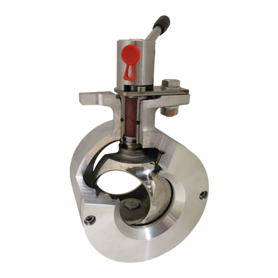
BALL SECTOR VALVE AL 74-KS / KSP
WARNING!
Risk for serious injury when valve with actuator is bench tested.
Avoid handling the valve with hands or fingers inside the valve! Be
very careful when handling a valve which has been in abrasive service.
Worn valve can have sharp edges on ball sector and seat.
GENERAL
AL 74-KS type KS and KSP are developed and used for controlling
gases, fluids, pulp suspensions and slurry. Through its construction
the valve can also be used as a bi-directional shut-off valve. Valve can
be supplied in different material combinations depending on type of
media and service, see table page 4. Valve can be used for temperatu-
res from -400C to +2000C (+2500C). The exact temperature range is
depending on pressure, media and sealing material. Contact your valve
supplier if any uncertainty. See page 5 for tables with pressure and
temperature limits.
FUNCTION
AL 74-KS is made from a half ball, a ball sector, which is journalled in
a valve body via two shafts. One part of the ball sector sphere is used
for shut-off. The other part of the sphere has a hole with a diameter
which is about 80% of the nominal valve size. The ball sector is turned
900 from fully open to fully close. Some smaller valve sizes have a
more reduced orifice and operation angle as follows; DN40/32 (700),
DN40/25 (600), DN25/15 (650), DN25/5 (600),
DN25/A-K (720).
ATTENTION!
Operating angle is max 90° and shall not be exceeded as it may cause
damage to the seat ring. If done so by mistake, the pressure on the
seat ring must be reduced! This is done by loosen the screws (item
11) on seat holding ring (item 2). Restore the ball sector to the right
position. Retighten the screws on the seat holding ring.
IDENTIFICATION
Valve size and material combination can be identified by marking code
on the valve body according to the following example:
PN 16
= Pressure class PN
g
= Standard flow direction
KS
= Type
DN 100
= Valve size DN
1
= Material combination
SS 2343
= Material in body
CHECK OF VALVE SIZE
The valve size can be checked by measuring the outlet port diameter
which is the same as the valve size. The inlet flow bore diameter is
always reduced to about 80% of the outlet port diameter. Sizes DN25
and 40 may be further reduced.
VALVE ACCEPTANCE INSPECTION
Make sure that the valve has not been damaged during transport and
that it is complying to your order. Valve body is marked with type,
pressure class PN, size DN, flow arrow, material code and, where
appropriate, CE-label with category and module according to PED
STORING
Valve shall be stored in a clean and dry area preventing corrosion and
fouling. It shall be operated to fully open position. Protection plates
shall not be removed until the valve shall be mounted.
INSTALLATION
This product shall only be inspected, installed and used by a person
who has relevant training or experience. If any questions or hesita-
tion, contact Axel Larsson AB. If the valve shall be equipped with ac-
tuator this shall be done before installation in the pipe line. Separate
instruction is supplied on request. Before installation of the valve,
check that the valve data is in conformity with actual type of service
with reference to media, pressure and temperature. If the valve shall
be used as shut-off valve against atmosphere at the end of the pipe,
where possible leakage can cause person injury or property damage,
there are special limits for max working pressure and, if necessary,
demands on blocking the actuator. Contact your valve supplier. Piping
shall be thoroughly cleaned. Check that the pipe flanges are parallel
and that the piping system can not be subject to uncontrolled forces
caused by pressure peaks, or pipe forces caused by variations in
temperature.
IMPORTANT!
Install the valve in such position that injury on person, or damage on
property, is avoided in case of leakage from sealing or flange joints.
Also, make sure that, in case of leakage, inflammable media do not
come in contact with electrical components or hot surfaces which
can cause fire or damage on property.
The valve shall be operated into fully open position after installation
and the pipe system be properly flushed before put into service.
4.650B_UK - 1
Advertisement
Table of Contents

Related Manuals for Axel Larsson 74-KS


Summary of Contents for Axel Larsson 74-KS
- Page 1 Separate instruction is supplied on request. Before installation of the valve, AL 74-KS is made from a half ball, a ball sector, which is journalled in check that the valve data is in conformity with actual type of service a valve body via two shafts.
-
Page 2: Flow Direction
Ref. 4.650B_UK - 2015-01-14. www.axel-larsson.se MANUAL BALL SECTOR VALVE AL 74-KS / KSP FLOW DIRECTION Attention! Check that the pipe is depressurized and drained. Great caution must The valve’s performance is equal regardless of flow direction. Alt- be taken when there is a risk for toxic or corrosive media is captured... - Page 3 Ref. 4.650B_UK - 2015-01-14. www.axel-larsson.se MANUAL BALL SECTOR VALVE AL 74-KS / KSP DN 300 DN 300 Part Body Seat holding ring Ball sector Bearing sleeve Saftety ring Shaft Shaft Seat support ring Bearing Seat ring Grub screw O-ring Sliding ring...
-
Page 4: Maintenance
Ref. 4.650B_UK - 2015-01-14. www.axel-larsson.se MANUAL BALL SECTOR VALVE AL 74-KS / KSP MAINTENANCE DN 300 (12") a) Loosen nuts (21), remove bolts (20) and clamping rings (19) Ramén Ball Sector valve requires no lubrication and a minimum of b) Remove inlet cover ring (2) maintenance. -
Page 5: After Reassembly
Ref. 4.650B_UK - 2015-01-14. www.axel-larsson.se MANUAL BALL SECTOR VALVE AL 74-KS / KSP After reassembly j) Mount the nut (12) slightly with fingers. Fasten the flange (1A) into a vice and tighten nut (12) hard with a box-spanner. Pressure test the valve with air from the valves outlet side and with k) Turn ball sector between open and closed a few times to ensure the valve closed. - Page 6 Ref. 4.650B_UK - 2015-01-14. www.axel-larsson.se MANUAL BALL SECTOR VALVE AL 74-KS / KSP Bearing (9) Sliding ring (13A) O-ring (13A) Fig. 3 - Tool for mounting shaft and drive shaft. Ball sector (3) Seat ring (10) Fig. 4 - Ball sector position when valve is closed.
Need help?
Do you have a question about the 74-KS and is the answer not in the manual?
Questions and answers