Table of Contents
Advertisement
Quick Links
V E G A I N D U S T R I E S L I M I T E D
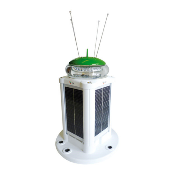
VLB-5X LED Beacon
Installation and Operation Manual
VLB-5X-SA-Stand Alone
Available colour range
Available models
Vertical divergence
Options
Product Version
Software version:
Manual version:
Date released:
AIS-Compatible
STAND ALONE & SELF CONTAINED
• Marine Beacon
• Bridge Light
• Aircraft Hazard Light
VLB-5X-SS-Standard Solar
VLB-5X Product Manual
Red, Green, White, Yellow or Blue
SA-Stand Alone (No Solar panels)
SS-Standard Solar 8W with 12Ah battery
LS1-Large Solar 16W with 12Ah Battery
LS2-Large Solar 16W with 24Ah Battery
7° Marine Beacon, Obstacle Light and
Wreck Light
Internal GPS for synchronising
RS232 Data port (RS485 optional)
Sync and monitor wire
AIS-compatible
1.00
8.11
1.2
Aug 2017
VLB-5X-LS-Large Solar
Advertisement
Table of Contents

Related Manuals for Vega Industries VLB-5X

Summary of Contents for Vega Industries VLB-5X
- Page 1 V E G A I N D U S T R I E S L I M I T E D VLB-5X LED Beacon AIS-Compatible Installation and Operation Manual STAND ALONE & SELF CONTAINED • Marine Beacon • Bridge Light •...
- Page 2 Serial Communications Protocol Compatibility VLB5X beacons with software versions lower than 811 (or 722 for Lead-Acid Battery variants) may not communicate correctly over the serial interface with a Vega AIS device. Please contact Vega Industries to arrange a software update. VLB-5X LED Beacon Page 2 of 53 VLB-5X V1.2...
- Page 3 Legal Notice Information in this document is subject to change without notice. Vega Industries Ltd. makes no warranty of any kind with regards to this material, including but not limited to, the implied warranties of merchantability and fitness for purpose. Vega Industries Ltd. shall not be liable for errors contained herein or for incidental or consequential damages in connection with the use of this material.
-
Page 4: Table Of Contents
Solar Body Breather Vent ....................10 Sealing ..........................10 Electrical ......................... 10 Electrical Connections ....................... 10 Battery Charging on VLB-5X SS and LS Beacons ..........10 SECTION 2 SETTING UP AND USING THE VLB-5X BEACON ......... 10 Getting Started ......................10 Solar Calculations .................... - Page 5 Default Settings ....................... 16 Programming Syntax ....................16 Visual Feedback when using the TVIR Programmer ..........17 The VLB-5X Will Not Enter Programming Mode ..............18 Becoming Familiar with the Syntax and Flash Feedback ........... 18 Deciding what Settings are required .................. 20 4.3.1 Programming or Reading Multiple Settings ................
-
Page 6: Overview Of The Vlb-5X Led Beacon
VLB-5X on www.vega-navigation.com to assist in the correct usage of the VLB-5X. Please note that reducing the range and the duty cycle of the beacon can lower the power requirement. Options Available There are three lens options for the VLB-5X beacon. -
Page 7: Additional Factory Options
The peak candela and peak current of each colour • While the VLB-5X is normally only used at night it is possible to operate the beacon during the day using a different intensity setting than is used at night. Automatic Schmidt Clausen Correction When a light is flashed, the intensity must be increased to maintain the lights visibility at the required distance. - Page 8 The VLB-5X will cap the intensity at the maximum candela allowed, reducing the range of the light.
-
Page 9: Mechanical Description
© Vega Industries Ltd, Aug 2017 Mechanical Description Construction The common parts of the VLB-5X are the beacon head, the base, and the connecting seal. The stand-alone (SA) model consists of these 3 parts and has a 1.5 metre 3 core cable fitted to provide the power connection for the beacon. -
Page 10: Solar Body Breather Vent
Protection is provided to prevent the overcharging of the battery. The solar charger is designed for the lead crystal battery. The battery on the VLB-5X has been specifically designed for the mounting configuration used in the VLB-5X. If a replacement battery is required please obtain the correct battery from Vega or one of Vega’s distributors. -
Page 11: Shipping Of The Vlb-5X
The 4 solar panels on the VLB-5X beacon are mounted 90 degrees apart from each other in azimuth. The inclination of the solar panels is 90 degrees from the horizontal. -
Page 12: Programming
For connecting to VPP-5X Solar Power Power Pack The VLB-5X SA Beacon is a sealed unit. If shortening the power cable the user must tin each cable core and reseal both external sheath and internal cores with heat shrink and marine sealant. -
Page 13: Levelling The Beacon
© Vega Industries Ltd, Aug 2017 The base of the VLB-5X beacon has been designed for 3 or 4 holes mounting on a 200mm diameter PCD. The base has through holes sized to take 316 Stainless steel M12 (1/2” UNC) bolts or rod. -
Page 14: Internal Gps Synchronization
The data port shares common circuitry with the IRDA port that is used for programming the VLB- 5X from a computer. Only one data port can be used by the VLB-5X at any time. Operation of the data ports is selectable using the Vega Remote TVIR programmer. -
Page 15: Changing The Battery On Self Contained Models
If additional O-rings are required, the part number for ordering is Oring130EPDM. When new O-rings are fitted ensure they have a coating of silicon grease before reassembly. To change the battery on the self-contained models of the VLB-5X: Unscrew the four screws holding the lantern head to the solar body. -
Page 16: Using The Vega Remote Tvir Programmer
The VLB-5X has two data ports, IRDA and the RS232/RS485. The RS232/RS485 port is only fitted if requested at time of order. The VLB-5X can only operate with one of the data ports at any time. The port being used is selectable using the programming mode options. The IRDA data port is required to be enabled to allow programming to occur from a computer. -
Page 17: Visual Feedback When Using The Tvir Programmer
FEATURE items represent the features of the light such as flash character and intensity. VALUES are the actual settings or value of the various features. Appendix A of this manual provides a Table for the programming features of the VLB-5X beacon. Please take the time to become familiar with the table before continuing. -
Page 18: The Vlb-5X Will Not Enter Programming Mode
The VLB-5X Will Not Enter Programming Mode If you find the VLB-5X will not enter the programming mode it will be caused by one of 4 reasons: • The battery in the TVIR programmer is missing, or the plastic battery insulator has not been removed, or the battery has low voltage. - Page 19 Press the red standby button for 5 seconds If the VLB-5X has been programmed for Calendar or auto storage mode, the flash response will be different. Enter the programming The light will flash once each time a key on the programmer is operated.
-
Page 20: Deciding What Settings Are Required
However, this can be time consuming to enter multiple settings, as it is necessary to wait for the VLB-5X to flash its response and return to normal operation before entering the programming mode again. -
Page 21: Custom Flash Character
= 000 Appendix C provides a work sheet, and an example, for programming a Custom Character If an error occurs when entering a custom character the VLB-5X will flash the error code of 3 quick flashes. Programming a custom character creates a flash character with code 999. To get the VLB-5X to use the custom character the value of 999 must be entered as the flash character. -
Page 22: Synchronising Options
Each light can be set to be a sync master or sync slave. As a slave the VLB-5X will not operate unless receiving sync pulses, however the slave will still generate a sync pulse when operating. -
Page 23: Operation Mode
N determines how long the VLB-5X has to see daylight before switching from “Storage” to “Normal” mode. N can be set from 0 to 9. Each increment increases the time the VLB-5X has to see daylight before switching by 10 minutes. -
Page 24: Programming Mode
N determines how long the VLB-5X has to see daylight before switching from “Storage” to “Normal” mode. N can be set from 0 to 9. Each increment increases the time the VLB-5X has to see daylight before switching by 10 minutes. -
Page 25: Security Pin Number
If you lose your PIN, please contact Vega. 5.11 Calendar The VLB-5X allows the programming of 5 pairs of calendar dates where the beacon will turn off at the first date, hibernate, and then return to “Normal” operation on the second date. Because the calendar operation continues when the beacon is in hibernation the background power is higher than if the VLB-5X was in storage mode. - Page 26 VLB-5X LED Beacon © Vega Industries Ltd, Aug 2017 The day of the month is a number between 01 and 31. The VLB-5X does not check the days entered against a particular month. The 31 of February for example would be seen by the VLB- 5X as the 3 of March.
- Page 27 Instruction Manual VLB-5X LED Beacon © Vega Industries Ltd, Aug 2017 Feature Value Flash response from VLB-5X Calendar Enable/Disable Disable Disable Enable Enable Enabled and Hibernating Read Enable/Disable Disable Enable Enabled and Hibernating Set Year YYYY (i.e. 2010) YYYY (i.e. 2010) Read Year YYYY (i.e.
-
Page 28: User Notes
Instruction Manual VLB-5X LED Beacon © Vega Industries Ltd, Aug 2017 User Notes VLB-5X LED Beacon Page 28 of 53 VLB-5X V1.2... -
Page 29: Appendix Aprogramming Table
Instruction Manual VLB-5X LED Beacon © Vega Industries Ltd, Aug 2017 APPENDIX A PROGRAMMING TABLE Operation Feature Value 1 = Program Mode 0 = Flash Character 000 – Fixed character 1YY – Isophase (ISO) 9 = Read Settings Default 601 2YY –... - Page 30 Instruction Manual VLB-5X LED Beacon © Vega Industries Ltd, Aug 2017 Operation Feature Value 1 = Program Mode 5 = Operation Mode 000 – Normal, also cancel Auto Storage/ Auto Leave Storage mode. 9 = Read Settings Default 000 007 – Test Alarm signal output (Alarm operates until beacon Normal leaves programming mode).
- Page 31 Instruction Manual VLB-5X LED Beacon © Vega Industries Ltd, Aug 2017 Operation Feature Value 1 = Program Mode 6 = Programming Mode/ RS232/ 000 – Disable IRDA and RS232, No Monitoring IRDA 001 – Enable IRDA, No Monitoring 9 = Read Settings 002 –...
- Page 32 Instruction Manual VLB-5X LED Beacon © Vega Industries Ltd, Aug 2017 Operation Feature Value Response 000 – Disable 000 – Disabled 0-0: Enable/Disable Calendar 001 - Enable 001 – Enabled Control 011 – Enabled and hibernating during off period Default 000 Disabled 000 –...
-
Page 33: Appendix Bvlb-5X Intensity Settings And Currents
Day off current/transport modes/storage mode with calendar disabled (mA) Day off current/transport modes/storage mode with calendar enabled (mA) Current consumption data for VLB-5X Options (add to day and night currents) IRDA enabled current (mA) RS232 enabled & externally connected current (mA) Monitor alarm current excluding external load 0.075... - Page 34 Instruction Manual VLB-5X LED Beacon © Vega Industries Ltd, Aug 2017 Table 2 VLB-5X Obstacle Lens Last update: 14 September 2015 Effective Current (mA) @ 20ºC Range Range Luminous Program (NM @ (NM @ Green White Yellow Blue Intensity Code 0.74T)
- Page 35 Instruction Manual VLB-5X LED Beacon © Vega Industries Ltd, Aug 2017 Table 3 VLB-5X FAA Hazard Light Last update: 13 May 2014 Effective Current (mA) @ Range Range Luminous Program (NM @ (NM @ Intensity Code 0.74T) 0.85T) (cd) 54.0 45.0...
- Page 36 © Vega Industries Ltd, Aug 2017 Using the tables: 1. The VLB-5X beacon is programmed for the effective intensity required. For example; a 4NM light at 0.74T has an effective candela of 37 candelas. Program code 0037 2. The bold numbers in the current tables indicate the effective candela settings that can be programmed for a particular colour.
-
Page 37: Appendix C Worksheet For A Custom Character
Instruction Manual VLB-5X LED Beacon © Vega Industries Ltd, Aug 2017 APPENDIX C WORKSHEET FOR A CUSTOM CHARACTER Fill out the table below for the values required to program a custom character. The steps to program a custom character is as follows Example given for Fl (2) 38.5sec (0.5sec on 2sec off 16sec on 20sec off) -
Page 38: Appendix Dvlb-5X Settings
Instruction Manual VLB-5X LED Beacon © Vega Industries Ltd, Aug 2017 APPENDIX D VLB-5X SETTINGS Complete the table for the required settings. It is only necessary to program the specific settings where they are different to the settings already programmed. -
Page 39: Appendix Evlb-5X Solar Power Calculation Example
Example 1: Calculate the peak intensity and the power consumption for a red VLB-5X operating at night, fitted with an internal GPS pulse sync unit. The calculation is made for the longest night to determine the highest energy needs of the light Night range = 4.0NM at 0.74T... - Page 40 Total energy used by light=T+V 0.16Ah For VLB-5X-SA Stand Alone unit the power source supplying the Beacon must be able to support the load of the beacon as calculated above. For VLB-5X-SS/LS Solar Powered beacons it is necessary to ensure the Solar-energy available and the battery capacity is sufficient to support the load of the Beacon.
- Page 41 Because of the shape of the VLB-5X solar pack it is necessary to have the solar energy figures for each of the solar panels. This means a different azimuth for each panel (90 degrees apart). The inclination of the panels is 90 degrees from the horizontal.
-
Page 42: Appendix Felectrical Connections To Vlb-5X Beacon
Instruction Manual VLB-5X LED Beacon © Vega Industries Ltd, Aug 2017 APPENDIX F ELECTRICAL CONNECTIONS TO VLB-5X BEACON Connections will vary with VLB-5X Model and Options ordered VLB-5X LED Beacon Page 42 of 53 VLB-5X V1.2... - Page 43 Instruction Manual VLB-5X LED Beacon © Vega Industries Ltd, Aug 2017 VLB-5X LED Beacon Page 43 of 53 VLB-5X V1.2...
-
Page 44: Appendix Gvlb-5X Beacon Dimensions
Instruction Manual VLB-5X LED Beacon © Vega Industries Ltd, Aug 2017 APPENDIX G VLB-5X BEACON DIMENSIONS Standalone Beacon Standard Self Contained Beacon VLB-5X LED Beacon Page 44 of 53 VLB-5X V1.2... - Page 45 Instruction Manual VLB-5X LED Beacon © Vega Industries Ltd, Aug 2017 Large Self Contained Beacon VPP-67 SS VPP-67 LS VLB-5X LED Beacon Page 45 of 53 VLB-5X V1.2...
-
Page 46: Appendix H 7° Marine Light Vertical Divergence Profiles
Instruction Manual VLB-5X LED Beacon © Vega Industries Ltd, Aug 2017 APPENDIX H 7° MARINE LIGHT VERTICAL DIVERGENCE PROFILES 1.00E+02 8.00E+01 6.00E+01 Green White Yellow 4.00E+01 Blue 2.00E+01 0.00E+00 -7.00 -5.00 -3.00 -1.00 1.00 3.00 5.00 7.00 VLB-5X LED Beacon Page 46 of 53 VLB-5X V1.2... -
Page 47: Appendix I Specifications Of Vlb-5X Beacon
Negative transition signal at start of flash character Max sink-current 1.6mA @18V positive supply GPS Synchronisation Factory option internal GPS module. Operates only when VLB-5X beacon is running. Synchronising Delay Synch pulse delay settable from 0 to 9.9 seconds Electrical Voltage 9 to 18 VDC, nominal 12.0 VDC... - Page 48 Instruction Manual VLB-5X LED Beacon © Vega Industries Ltd, Aug 2017 RS485 2-wire differential, bidirectional half-duplex serial interface, custom protocol. Materials for Beacon Lens Moulded acrylic (PMMA) Moulded UV stabilised ASA plastic with central bird spike Body Injection Moulded UV Stabilised Nylon 6/6 with 30% glass fill Additional Bird Spikes 4 spikes, 316 Stainless steel.
- Page 49 Instruction Manual VLB-5X LED Beacon © Vega Industries Ltd, Aug 2017 TVIR Programmer Coding Scheme: RC5 code with centre frequency 36.7 kHz Dimensions: 87mm x 41mm x 6.5mm Weight: 18gms Power Supply: 1 x 3V lithium coin cell battery, CR2025 type...
-
Page 50: Appendix Jflash Character Table With Programming Codes
Instruction Manual VLB-5X LED Beacon © Vega Industries Ltd, Aug 2017 APPENDIX J FLASH CHARACTER TABLE WITH PROGRAMMING CODES FIXED DETAIL FLASH DETAIL 000 Fixed 306 FL 2s 0.4 0.4s, 1.6s 307 FL 2s 0.5 0.5s, 1.5s DETAIL 308 FL 2s 0.7 0.7s, 1.3s... - Page 51 Instruction Manual VLB-5X LED Beacon © Vega Industries Ltd, Aug 2017 FLASH DETAIL DETAIL MULTI FLASH 436 Fl(2) 20s 1.0 3.0 1s, 3s, 1s, 15s 349 FL 10s 0.8 0.8s, 9.2s 350 FL 10s 1.0 1s, 9s 437 Fl(2) 25s 1.0 1.0 1s, 1s, 1s, 22s 351 FL 10s 1.5...
- Page 52 Instruction Manual VLB-5X LED Beacon © Vega Industries Ltd, Aug 2017 DETAIL DETAIL VERY QUICK QUICK 0.2s, 0.3s 0.5s, 0.5s, 0.5s, 0.5s, 0.5s, 0.5s, 0.5s, 16.5s 501 VQ 0.5s 0.20 626 Q(4) 20s 0.5 0.2s, 0.4s 0.3s, 0.7s, [x 8], 0.3s, 6.7s 502 VQ 0.6s 0.20...
-
Page 53: Appendix Kvlb-5X Beacon Product Codes
Instruction Manual VLB-5X LED Beacon © Vega Industries Ltd, Aug 2017 DETAIL SPECIAL DETAIL MORSE 823 MO(U) 15s 1.30 1.3s, 0.7s, 1.3s, 0.7s, 3.3s, 7.7s 914 Fl (4) 10s 3 x (0.4s, 1.2s), 0.4s, 4.8s 915 LFl 10s 2.15s, 7.85s 916 MO (A) 5s 0.45s, 0.25s, 1.45s, 2.85s...
Need help?
Do you have a question about the VLB-5X and is the answer not in the manual?
Questions and answers