Table of Contents
Advertisement
V E G A I N D U S T R I E S L I M I T E D
VLB-67 LED Beacon
Installation and Operation Manual
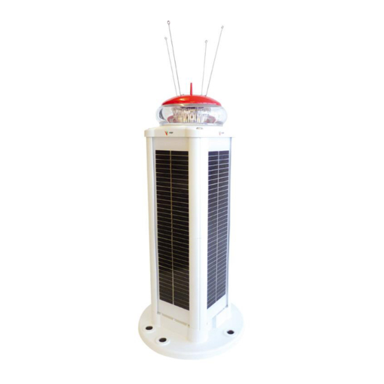
VLB-67-SA-Stand Alone
Available colour range
Available models
Vertical divergence
Options
Product Version
Software version:
Manual version:
Date released:
Status:
STAND ALONE & SELF CONTAINED
Marine Beacon
Bridge Light
Aircraft Hazard Light
VLB-67-SS-Standard Solar
VLB-67 Product Manual
Red, Green, White, Yellow or Blue
SA-Stand Alone (No Solar panels)
SS-Standard Solar 8W with 12Ah battery
LS1-Large Solar 16W with 12Ah Battery
LS2-Large Solar 16W with 24Ah Battery
7° Marine Beacon and Obstacle Light
Internal GPS for synchronising
RS232 Data port (RS485 optional)
Sync and monitor wire
SA and SS version: 4.00
LS1 and LS2 version: 5.00
7.11
1.0.17
24 July 2014
AHT Released
VLB-67-LS-Large Solar
Advertisement
Table of Contents

Related Manuals for Vega Industries VLB-67-SA

Summary of Contents for Vega Industries VLB-67-SA
- Page 1 VLB-67 LED Beacon Installation and Operation Manual STAND ALONE & SELF CONTAINED Marine Beacon Bridge Light Aircraft Hazard Light VLB-67-SA-Stand Alone VLB-67-SS-Standard Solar VLB-67-LS-Large Solar VLB-67 Product Manual Red, Green, White, Yellow or Blue Available colour range SA-Stand Alone (No Solar panels)
- Page 2 Instruction Manual VLB-67 LED Beacon © Vega Industries Ltd, July 2014 Manual revision history Manual Version Released Description of Change Software version VLB-67 Serial number Dec 2009 First issue. 1.0.1 8 Mar 2010 (Not affected) Applicable to all Correction to Yellow Appendix A currents for intensities below 37cd.
- Page 3 Legal Notice Information in this document is subject to change without notice. Vega Industries Ltd. makes no warranty of any kind with regards to this material, including but not limited to, the implied warranties of merchantability and fitness for purpose. Vega Industries Ltd. shall not be liable for errors contained herein or for incidental or consequential damages in connection with the use of this material.
-
Page 4: Table Of Contents
Self Contained Model ......................10 6.0 Programming ......................11 7.0 Installing the VLB-67 Beacon ..................11 Bird Spikes ........................... 11 Wiring from VLB-67-SA & SAP Stand Alone Beacon ............11 7.2.1 VLB-67 Base Compartment ....................11 Mounting the VLB-67 Beacon....................12 7.3.1... - Page 5 Instruction Manual VLB-67 LED Beacon © Vega Industries Ltd, July 2014 SECTION 4 PROGRAMMING ..................14 1.0 Programming Methods ....................14 Using the Vega Remote TVIR Programmer ................15 Using a Computer ........................ 15 2.0 Default Settings ......................15 3.0 Programming Syntax ....................15 4.0 Visual Feedback when using the TVIR Programmer ..........
-
Page 6: Section 1 Overview Of The Vlb-67 Led Beacon
Instruction Manual VLB-67 LED Beacon © Vega Industries Ltd, July 2014 SECTION 1 OVERVIEW OF THE VLB-67 LED BEACON Introduction to the VLB-67 LED Beacon The VLB-67 is a feature rich product allowing the user to program many advanced features not normally required for standard navigation applications. -
Page 7: Additional Factory Options
Instruction Manual VLB-67 LED Beacon © Vega Industries Ltd, July 2014 the Stand Alone (SAP) light head and VPP-67 solar body. Note that the solar power regulator is located in the lantern and not in the VPP-67 Solar Power Pack. In applications requiring more solar power the solar power pack can be substituted with the larger capacity VPP-66. -
Page 8: Mechanical Description
Instruction Manual VLB-67 LED Beacon © Vega Industries Ltd, July 2014 Mechanical Description Construction The common parts of the VLB-67 are the beacon head, the base, and the connecting seal. The SA-Stand Alone model consists of these 3 parts and has a 1.5metre 3 core cable fitted to provide the power... -
Page 9: Solar Body Breather Vent
Instruction Manual VLB-67 LED Beacon © Vega Industries Ltd, July 2014 Solar Body Breather Vent The solar body has been fitted with a membrane vent to allow pressure equalization, and to release any hydrogen gas that may build up from the battery. The membrane vent is located at the top of the body behind one of the solar panels. -
Page 10: Solar Calculations
Instruction Manual VLB-67 LED Beacon © Vega Industries Ltd, July 2014 Solar Calculations If the solar calculations are being done manualy it is necessary to determine the energy contribution for each solar panel taking into account the azimuth and inclination angles. Examples for the solar calculations are provided in Appendix E. -
Page 11: Programming
7.2.1 VLB-67 Base Compartment The base of the VLB-67 Beacon is designed to provide space to fit a AC to DC switch-mode power supply to allow the VLB-67-SA Stand Alone model to be mains powered. Vega will only supply the Stand Alone model as a 12VDC unit and if a mains supply is required the needs to be done by the user. -
Page 12: Mounting The Vlb-67 Beacon
VLB-67 beacon has been manufactured. Hardwire Synchronization The VLB-67-SA Stand Alone beacon comes with the hardwire sync wire included in the power cable. Because of the nature of the self-contained beacon no external wiring is supplied with the standard option. -
Page 13: Internal Gps Synchronization
Instruction Manual VLB-67 LED Beacon © Vega Industries Ltd, July 2014 Internal GPS Synchronization It is necessary to take into account the power consumption of the GPS unit in any power calculations. The GPS sync unit only operates when the beacon is programmed to run (night or day/night). -
Page 14: Changing The Battery On Self Contained Models
Instruction Manual VLB-67 LED Beacon © Vega Industries Ltd, July 2014 Changing the Battery on Self Contained Models Ensure the correct replacement battery is being used. This should be an EBAT-VGA-SL12-12U available from Vega or a Vega Distributor. It is recommended that the O-rings on the solar body seals be replaced at the same time as the battery. -
Page 15: Using The Vega Remote Tvir Programmer
Instruction Manual VLB-67 LED Beacon © Vega Industries Ltd, July 2014 The Beacon will be shipped with a default setting for programming with the Remote TVIR Programmer. The programming mode will have to be changed to allow computer programming. Using the Vega Remote TVIR Programmer During programming the VLB-67 the beacon will provide visual feedback by flashing as the keys are operated on the IR programmer. -
Page 16: Visual Feedback When Using The Tvir Programmer
Instruction Manual VLB-67 LED Beacon © Vega Industries Ltd, July 2014 System Information Operation 3 Calendar Control Operation 4 Optional PIN code Operation 7 Read settings Operation 9 FEATURE items represent the features of the light such as flash character and intensity. -
Page 17: The Vlb-67 Will Not Enter Programming Mode
Instruction Manual VLB-67 LED Beacon © Vega Industries Ltd, July 2014 The flash sequence for entering and exiting the programming mode is adjusted if the VLB-67 has been programmed to use Calendar or Auto Storage. This has been done in order to provide an indication that the VLB-67 has been programmed in either of these modes. - Page 18 Instruction Manual VLB-67 LED Beacon © Vega Industries Ltd, July 2014 The programming sequence to enter this flash character is 10602 The light will give 4 quick flashes to indicate it has entered programming Enter programming mode mode Press the red standby button...
-
Page 19: Deciding What Settings Are Required
Instruction Manual VLB-67 LED Beacon © Vega Industries Ltd, July 2014 Read System Information To read the current level of the battery or 12VDC supply, determine the Syntax from Appendix A: Operation =System Checks Feature =Battery Voltage The programming sequence to get the information is... -
Page 20: Custom Flash Character
Instruction Manual VLB-67 LED Beacon © Vega Industries Ltd, July 2014 set if advised to Vega at the time of order. These would then be available for programming under Custom character type 9YY. Operation =Program (or read) =1 (or 9) -
Page 21: Synchronising Options
Instruction Manual VLB-67 LED Beacon © Vega Industries Ltd, July 2014 It is the effective intensity of the VLB-67 that is programmed. The peak intensity is controlled automatically according to the flash character (Schmidt-Clausen correction) to maintain the required effective intensity. -
Page 22: Operation Mode
Instruction Manual VLB-67 LED Beacon © Vega Industries Ltd, July 2014 Operation Mode The Operation Mode provides control of how the VLB-67 will operate. Normal (000) Allows General Operation with no advanced options Storage (009) Allows Operation in low power mode (Asleep). A TVIR programmer is required to put the VLB-67 in and out of this mode. -
Page 23: Programming Mode
Instruction Manual VLB-67 LED Beacon © Vega Industries Ltd, July 2014 Switch time is 2 minutes of daylight Switch time is 12 minutes of daylight Switch time is 22 minutes of daylight etc. Y determines how the VLB will activate the Auto Store mode. -
Page 24: Security Pin Number
Instruction Manual VLB-67 LED Beacon © Vega Industries Ltd, July 2014 All information is in numeric format and represented by a series of flashes 0.1 sec on, 0.1 sec off, separated by 0.5 sec gap between numbers. The Voltage level is provided in tenths of a volt. - Page 25 Instruction Manual VLB-67 LED Beacon © Vega Industries Ltd, July 2014 Feature Value Flash response from VLB-67 Calendar Enable/Disable Disable Disable Enable Enable Enabled and Hibernating Read Enable/Disable Disable Enable Enabled and Hibernating Set Year YYYY (i.e. 2010) YYYY (i.e. 2010) Read Year YYYY (i.e.
-
Page 26: User Notes
Instruction Manual VLB-67 LED Beacon © Vega Industries Ltd, July 2014 User Notes VLB-67 LED Beacon Page 26 of 52 VLB-67 V1.0.17... -
Page 27: Appendix Aprogramming Table
Instruction Manual VLB-67 LED Beacon © Vega Industries Ltd, July 2014 APPENDIX A PROGRAMMING TABLE Operation Feature Value 1 = Program Mode 0 = Flash Character 000 – Fixed character 1YY – Isophase (ISO) 9 = Read Settings Default 601 2YY –... - Page 28 Instruction Manual VLB-67 LED Beacon © Vega Industries Ltd, July 2014 Operation Feature Value 1 = Program Mode 5 = Operation Mode 000 – Normal, also cancel Auto Storage/ Auto Leave Storage mode. 9 = Read Settings Default 000 007 – Test Alarm signal output (Alarm operates until Normal beacon leaves programming mode).
- Page 29 Instruction Manual VLB-67 LED Beacon © Vega Industries Ltd, July 2014 Operation Feature Value 1 = Program Mode 6 = Programming Mode/ RS232/ 000 – Disable IRDA and RS232, No Monitoring IRDA 001 – Enable IRDA, No Monitoring 9 = Read Settings 002 –...
- Page 30 Instruction Manual VLB-67 LED Beacon © Vega Industries Ltd, July 2014 Operation Feature Value Response 000 – Disable 000 – Disabled 0-0: Enable/Disable Calendar 001 - Enable 001 – Enabled Control 011 – Enabled and hibernating during off period Default 000 Disabled 000 –...
-
Page 31: Appendix B Vlb-67 Intensity Settings And Currents
Instruction Manual VLB-67 LED Beacon © Vega Industries Ltd, July 2014 APPENDIX B VLB-67 INTENSITY SETTINGS AND CURRENTS Table 1 7° (±3.5°) Divergence Marine Lens Last update: 1/04/2011 Effective Current (mA) @ 20ºC Range Range Luminous Program (NM @ (NM @... - Page 32 Instruction Manual VLB-67 LED Beacon © Vega Industries Ltd, July 2014 Table 2 VLB-67 Obstacle Lens Last update: 13 August 2013 Effective Current (mA) @ 20ºC Range Range Luminous Program (NM @ (NM @ Green White Yellow Blue Intensity Code 0.74T)
- Page 33 Instruction Manual VLB-67 LED Beacon © Vega Industries Ltd, July 2014 Using the tables: 1. The VLB-67 beacon is programmed for the effective intensity required. For example a 4NM light at 0.74T has an effective candela of 37 Candela. Program code 0037 2.
-
Page 34: Appendix C Worksheet For A Custom Character
Instruction Manual VLB-67 LED Beacon © Vega Industries Ltd, July 2014 APPENDIX C WORKSHEET FOR A CUSTOM CHARACTER Fill out the table below for the values required to program a custom character. The steps to program a custom character is as follows Example given for Fl (2) 38.5sec (0.5sec on 2sec off 16sec on 20sec off) -
Page 35: Appendix Dvlb-67 Settings
Instruction Manual VLB-67 LED Beacon © Vega Industries Ltd, July 2014 APPENDIX D VLB-67 SETTINGS Complete the table for the required settings required. It is only necessary to program the specific settings where they are different to the settings already programmed. -
Page 36: Appendix E Vlb-67 Solar Power Calculation Example
Instruction Manual VLB-67 LED Beacon © Vega Industries Ltd, July 2014 APPENDIX E VLB-67 SOLAR POWER CALCULATION EXAMPLE DETERMINE THE POWER CONSUMPTION FOR A VLB-67 FOR A SPECIFIED RANGE AND FLASH CHARACTER To determine the power requirement of the VLB-67 the following information is required. - Page 37 Total energy used by light=T+V 0.16Ah For VLB-67-SA Stand Alone unit the power source supplying the Beacon must be able to support the load of the beacon as calculated above. For VLB-67-SS/LS Solar Powered beacons it is necessary to ensure the Solar-energy available and the battery capacity is sufficient to support the load of the Beacon.
- Page 38 Instruction Manual VLB-67 LED Beacon © Vega Industries Ltd, July 2014 Step 2 Determine the energy available from the solar panels at the location the beacon Now that the worst-case load is determined for the beacon it is necessary to determine what size solar body is required to support the beacon.
-
Page 39: Appendix Felectrical Connections To Vlb-67 Beacon
Instruction Manual VLB-67 LED Beacon © Vega Industries Ltd, July 2014 APPENDIX F ELECTRICAL CONNECTIONS TO VLB-67 BEACON Connections will vary with VLB-67 Model and Options ordered VLB-67 LED Beacon Page 39 of 52 VLB-67 V1.0.17... - Page 40 Instruction Manual VLB-67 LED Beacon © Vega Industries Ltd, July 2014 VLB-67 LED Beacon Page 40 of 52 VLB-67 V1.0.17...
-
Page 41: Appendix Gvlb-67 Data Port Protocol
The VLB-67 Monitoring protocol provides a human and machine-readable format for status information generated by the VLB-67 beacon. The primary purpose is to provide data compatible with Vega Industries VegaWeb monitoring devices. The data is also suitable for monitoring beacon status through third party applications. - Page 42 Instruction Manual VLB-67 LED Beacon © Vega Industries Ltd, July 2014 Outgoing Data: Each data package uses a pseudo XML format consisting of a tag followed by data then a terminator. Tags are always three characters surrounded by the ‘<’ and ‘>’ symbols.
-
Page 43: Appendix Hvlb-67 Beacon Dimensions
Instruction Manual VLB-67 LED Beacon © Vega Industries Ltd, July 2014 Current = LDI * 0. 64453 milliamps Current = LOI * 0. 64453 milliamps Internal diagnostic variable 1 – Beacon is Good ( no alarm ) 1 – Day is indicated Example Data: <BAT>424/<LIT>0/<TMP>376/<SLR>0/<BCI>-... - Page 44 Instruction Manual VLB-67 LED Beacon © Vega Industries Ltd, July 2014 Large Self Contained Beacon VPP-67 SS VPP-67 LS VLB-67 LED Beacon Page 44 of 52 VLB-67 V1.0.17...
-
Page 45: Appendix I 7° Marine Light Vertical Divergence Profiles
Instruction Manual VLB-67 LED Beacon © Vega Industries Ltd, July 2014 APPENDIX I 7° MARINE LIGHT VERTICAL DIVERGENCE PROFILES VLB-67 LED Beacon Page 45 of 52 VLB-67 V1.0.17... -
Page 46: Appendix J Specifications Of Vlb-67 Beacon
Instruction Manual VLB-67 LED Beacon © Vega Industries Ltd, July 2014 APPENDIX J SPECIFICATIONS OF VLB-67 BEACON Optical Light Source High-Intensity Light-Emitting Diodes Operating temperature controlled to protect LEDs Colours Available Red, Green, White, Yellow, Blue IALA Recommendation E-200-1 part1... - Page 47 Instruction Manual VLB-67 LED Beacon © Vega Industries Ltd, July 2014 RS485 2-wire differential, bidirectional half-duplex serial interface, custom protocol. Materials for Beacon Lens Moulded acrylic (PMMA) Moulded UV stabilised ASA plastic with central bird spike Body Injection Moulded UV Stabilised Nylon 6/6 with 30% glass fill Additional Bird Spikes 4 spikes, 316 Stainless steel.
- Page 48 Instruction Manual VLB-67 LED Beacon © Vega Industries Ltd, July 2014 TVIR Programmer Coding Scheme: RC5 code with centre frequency 36.7 kHz Dimensions: 87mm x 41mm x 6.5mm Weight: 18gms Power Supply: 1 x 3V lithium coin cell battery, CR2025 type...
-
Page 49: Appendix Kflash Character Table With Programming Codes
Instruction Manual VLB-67 LED Beacon © Vega Industries Ltd, July 2014 APPENDIX K FLASH CHARACTER TABLE WITH PROGRAMMING CODES FIXED DETAIL FLASH DETAIL 000 Fixed 306 FL 2s 0.4 0.4s, 1.6s 307 FL 2s 0.5 0.5s, 1.5s 308 FL 2s 0.7 0.7s, 1.3s... - Page 50 Instruction Manual VLB-67 LED Beacon © Vega Industries Ltd, July 2014 FLASH DETAIL DETAIL MULTI FLASH 436 Fl(2) 20s 1.0 3.0 1s, 3s, 1s, 15s 349 FL 10s 0.8 0.8s, 9.2s 350 FL 10s 1.0 1s, 9s 437 Fl(2) 25s 1.0 1.0 1s, 1s, 1s, 22s 351 FL 10s 1.5...
- Page 51 Instruction Manual VLB-67 LED Beacon © Vega Industries Ltd, July 2014 DETAIL DETAIL VERY QUICK QUICK 0.2s, 0.3s 0.5s, 0.5s, 0.5s, 0.5s, 0.5s, 0.5s, 0.5s, 16.5s 501 VQ 0.5s 0.20 626 Q(4) 20s 0.5 0.2s, 0.4s 0.3s, 0.7s, [x 8], 0.3s, 6.7s 502 VQ 0.6s 0.20...
-
Page 52: Appendix Lvlb-67 Beacon Product Codes
Instruction Manual VLB-67 LED Beacon © Vega Industries Ltd, July 2014 SPECIAL DETAIL DETAIL MORSE 914 Fl (4) 10s 3 x (0.4s, 1.2s), 0.4s, 4.8s 823 MO(U) 15s 1.30 1.3s, 0.7s, 1.3s, 0.7s, 3.3s, 7.7s 915 LFl 10s 2.15s, 7.85s 916 MO (A) 5s 0.45s, 0.25s, 1.45s, 2.85s...
Need help?
Do you have a question about the VLB-67-SA and is the answer not in the manual?
Questions and answers