Table of Contents
Advertisement
Quick Links
DKG-117 User Manual
FEATURES
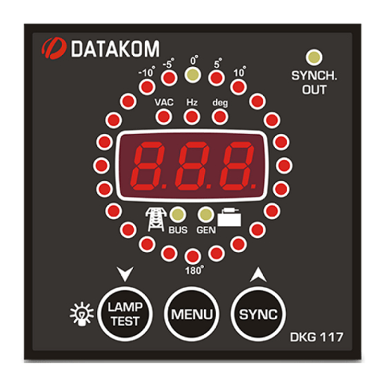
24 led circular synchroscope
Programmable ΔV, Δf, Δθ for check synch
relay
1 phase genset voltage input
1 phase busbar voltage input
Synch Check Enable input
Dead Bus Enable input
Auto power off
Adjustable parameters
Front panel configurable
Survives cranking dropouts
LED displays
Sealed front panel
Plug-in connection system for easy
replacement
Small dimensions (72x72x52mm)
Low cost
DKG-117
SYNCHROSCOPE AND
CHECK SYNCH RELAY
MEASUREMENTS
Generator Volt: U-N
Generator Frequency
Busbar Volts: R-N
Busbar Frequency
Frequency difference busbar-generator
Voltage difference busbar-generator
Phase angle busbar-phase U
V-01
(24.03.2014)
- 1 -
Advertisement
Table of Contents

Subscribe to Our Youtube Channel
Related Manuals for Datakom DKG-117


Summary of Contents for Datakom DKG-117
- Page 1 DKG-117 User Manual V-01 (24.03.2014) DKG-117 SYNCHROSCOPE AND CHECK SYNCH RELAY FEATURES MEASUREMENTS Generator Volt: U-N 24 led circular synchroscope Programmable ΔV, Δf, Δθ for check synch Generator Frequency Busbar Volts: R-N relay 1 phase genset voltage input Busbar Frequency...
-
Page 2: Table Of Contents
DKG-117 User Manual V-01 (24.03.2014) TABLE OF CONTENTS Section 1. INSTALLATION 1.1. Introduction to the Control Panel 1.2. Mounting the Unit 1.3. Wiring the Unit 2. INPUTS AND OUTPUTS 3. DISPLAYS 3.1. Led Displays 3.2. Digital Display 4. OPERATION 5. OTHER FEATURES 5.1. -
Page 3: Installation
DKG-117 User Manual V-01 (24.03.2014) 1. INSTALLATION 1.1 Introduction to the Control Panel The unit is a display and control module used in manual synchronization and protection panels. It monitors the voltage and frequency of 2 independent power networks and shows the measured values on its 3-digit digital display. -
Page 4: Wiring The Unit
DKG-117 User Manual V-01 (24.03.2014) 1.3 Wiring the Unit WARNING: THE UNIT IS NOT FUSED. Use external fuses for Busbar phase: R, Generator phase: U, Battery positive: BAT(+). Install the fuses as nearly as possible to the unit in a place easily accessible for the user. -
Page 5: Inputs And Outputs
DKG-117 User Manual V-01 (24.03.2014) 2. INPUTS AND OUTPUTS Term Function Technical data Description GENSET PHASE-L1 Generator phase Connect the generator phase to this input. The input, 0-300V-AC generator phase voltage upper and lower limits are programmable. GENERATOR NEUTRAL Input, 0-300V-AC Neutral terminal for the generator phase. -
Page 6: Displays
DKG-117 User Manual V-01 (24.03.2014) 3. DISPLAYS 3.1 Led Displays The unit has 30 LEDs, divided in 4 groups: -Group_1: Synchronoscope: this group indicates the instantenous phase angle of the genset voltage with reference to the busbar voltage. When both networks are in synchronization, the upper center yellow led with 0º... -
Page 7: Digital Display
DKG-117 User Manual V-01 (24.03.2014) 3.2 Digital Display The unit has a three digit seven segment display. It shows: -Measured parameters, -Parameter names, -Program parameters. The navigation between different parameters is made with the MENU pushbutton. When the MENU key is hold pressed, the parameter name will be displayed. -
Page 8: Other Features
DKG-117 User Manual V-01 (24.03.2014) 5. OTHER FEATURES 5.1 Synchronization Checking The unit will check the synchronization only when both genset and busbar phase voltages are within programmed limits and the synchronization is enabled either with the SYNCHRONIZATION CHECK ENABLE signal or the SYNCH pushbutton. -
Page 9: Programming
DKG-117 User Manual V-01 (24.03.2014) 6. PROGRAMMING The program mode is used to program the timers and operational limits of the unit. To enter the program mode, press the MENU button for 5 seconds. The program mode will not affect the operation of the unit. Thus programs may be modified anytime, even while the genset is running. -
Page 10: Troubleshooting
DKG-117 User Manual V-01 (24.03.2014) 7. TROUBLESHOOTING AC voltages or frequency displayed on the unit are not correct: -Check engine body grounding, it is necessary. -The error margin of the unit is +/- 3 volts. -If there are faulty measurements only when the engine is running, there may be a faulty charging alternator or voltage regulator on the engine. -
Page 11: Technical Specifications
DKG-117 User Manual V-01 (24.03.2014) 9. TECHNICAL SPECIFICATIONS Generator voltage: 300 V-AC max. (Ph-N) Generator frequency: 0-100 Hz. Busbar voltage: 300 V-AC max. (Ph-N) Busbar frequency: 50/60 Hz. Digital inputs: 0 - 30 V-DC. Internally connected to battery positive via 4700 ohm resistor. -
Page 12: Connection Diagram
DKG-117 User Manual V-01 (24.03.2014) 10. CONNECTION DIAGRAM DATAKOM Electronics Ltd. Tel: +90-216-466 84 60 Fax: +90-216-364 65 65 e-mail: datakom@datakom.com.tr http: www.datakom.com.tr - 12 -...
Need help?
Do you have a question about the DKG-117 and is the answer not in the manual?
Questions and answers