
Related Manuals for ELECTROTEK AW200SG MINI MICRO


Summary of Contents for ELECTROTEK AW200SG MINI MICRO
- Page 1 ANAEROBIC WORKSTATION (AW200SG (MINI MICRO MANUAL PLEASE READ THIS MANUAL CAREFULLY BEFORE OPERATION Burnt Mill, Elizabeth Way Harlow, Essex, CM20 2HU UK 44-45 met@munro-group.co.uk MUNRO.6.22...
-
Page 2: Table Of Contents
CONTENTS GENERAL ARRANGEMENT DRAWING OF ANAEROBIC WORKSTATION GENERAL SPECIFICATION GAS SUPPLIES ELECTRICAL SUPPLES INSTALLATION OF GAS AND ELECTRIC DRAWING ASSEMBLY INSTRUCTIONS DRAWING CHECKING THE INCUBATOR ATMOSPHERE FOR OXYGEN PREPARING THE ANAEROBIC INDICATOR SOLUTION COMMISSIONING THE CABINET 10. CHECKING THE GAS FLOW 11. -
Page 3: General Arrangement Drawing Of Anaerobic Workstation
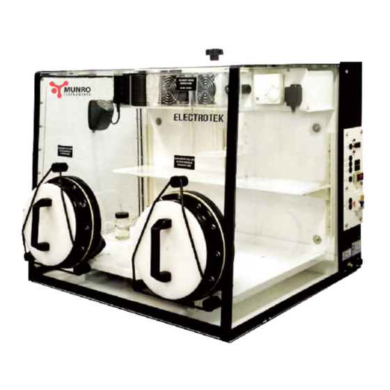
GENERAL ARRANGEMENT OF AW200SG ANAEROBIC CABINET Removable lock lid Fans Humidistat Spotlight Power socket Removable exterior port covers complete with retaining clips 22 1/2" (572mm) Condensation drain bottle 1 1/2" 27" (686mm) (38mm) Heating chamber Petri dish entry lock Bare hand operation ports Shelf Bottom door of lock... -
Page 4: General Specification
GENERAL SPECIFICATION MODEL AW200SG (MINI MICRO) MAIN CHAMBER INCUBATION CAPACITY 200 Petri Dishes DOOR SEALING Manual Mixed Gas (10% H2 + 10% CO2 + 80% N2) OXYGEN REMOVAL FROM AIRLOCK Positive Pressure flushing FABRICATION MATERIAL Acrylic OVERALL DIMENSIONS Length 27" 686mm Depth 25"... -
Page 5: Gas Supplies
GAS SUPPLIES This Anaerobic Cabinet requires one gas cylinders fitted with a two stage regulator. The output side of the regulator should have a range of 0 - 50 p.s.i. (3.3 bar). The gas cylinder should contain: 10% Hydrogen + 10% Carbon Dioxide + 80% Nitrogen CAUTION: GAS CONTAINING MORE THAN 10% HYDROGEN SHOULD NOT BE USED UNDER ANY CIRCUMSTANCES... -
Page 6: Installation Of Gas And Electric Drawing
INSTALLING THE GAS AND ELECTRICAL SUPPLY TO THE AW200SG WORKSTATION 2 stage pressure regulator Set outlet pressure sufficient to maintain pressure at inlet to cabinet Primary gauge showing pressure in bottle Pressure regulator setting 30 psi On/Off tap (2.0 bar) with gas flowing Electrical supply 220/240V AC 6mm diameter flexible 50Hz... -
Page 7: Assembly Instructions Drawing
AW200SG ASSEMBLY INSTRUCTIONS DRAWING Fit the indicator pump on hook provided and plug into this socket Air Exhaust Indicator solution bottle fits here Air Inlet Powder Bung Sleeve assy. 'O' ring Port Cover Conditioner Catalyst Place the conditioning sachet then the catalyst in the channels under the tray in the order shown. -
Page 8: Checking The Incubator Atmosphere For Oxygen
CHECKING THE INCUBATOR ATMOSPHERE FOR OXYGEN The Anaerobic Indicator Solution will indicate traces of Oxygen in the incubator atmosphere by changing colour from being clear when the atmosphere is anaerobic to being blue when oxygen is present. The Indicator Solution is held in a small bottle located in the bottom of the incubator and is held in position by a plastic holder. -
Page 9: Commissioning The Cabinet
COMMISSIONING THE CABINET Check all the following points before starting to commission the workstation. Switch "OFF" the cabinet at the Mains ELCB switch. The gas flow has been set at the factory to 35 litres per minute. Open the mixed gas pressure regulator fitted to the gas bottle sufficiently high to maintain an inlet pressure to the cabinet of approximately 30 psi (2.0 Bar) with the gas flowing. -
Page 10: Checking The Gas Flow
CHECKING THE GAS FLOW To check the Gas Flow into the Workstation the following equipment is required: 1. Gas Flow Meter (0 – 35 Litres per minute) 2. Pressure Gauge (0 – 3.3 Bar) Connect up the equipment as shown and lift lid as shown. Gas Out Flow Meter Pressure Gauge... -
Page 11: Working Inside The Cabinet With Bare Hands
WORKING INSIDE THE CABINET WITH BARE HANDS The inside of the sleeve is always held at positive pressure by the Gas Pressure Switch, therefore if the Bung is removed from the Cuff, gas will flow out of the cabinet and no oxygen will enter. To insert the hand into the cabinet, first remove the port cover by placing the neoprene retainer on each side of the port as shown and put the covers in a safe place. -
Page 12: Sleeve Assembly
SLEEVE ASSEMBLY The Most likely part of the sleeve assembly to suffer damage is the cuff. This can be replaced by following the diagrams shown below. The assembly consists of four parts:- 1. The sleeve 2. The rigid cuff 3. The wrist cuff 4. -
Page 13: Removal Of Condensation From Inside The Incubator
THE REMOVAL OF CONDENSATION FROM INSIDE THE INCUBATOR Water vapour accumulates inside the incubator atmosphere from two sources, firstly from the evaporation of the media in the Petri dishes and secondly by the hydrogen and the traces of oxygen being linked together by the palladium catalyst. -
Page 14: Transferring Items Into The Incubator
TRANSFERRING ITEMS INTO THE INCUBATOR The workstation is supplied with four stainless steel petri dish holders, each capable of holding ten dishes. These are used for transferring dishes into and out of the cabinet and for stacking them whilst they are being incubated. -
Page 15: The Gas Circulation System
THE GAS CIRCULATION SYSTEM The fan units pick up the cooler incubator atmosphere which has been forced to the top of the incubator and first passes it over the warm heater. This warmer gas is now forced down the channel at the back of the cabinet then it passes under the bottom shelf of the incubator where it first meets the sachets of Conditioner and then the sachets of Catalyst. -
Page 16: Test Record Sheet
TEST RECORD SHEET MODEL AW200SG SERIAL NO CUSTOMER MIXED GAS FLOW 35 L / MIN MIXED GAS INPUT PIPE SIZE 6 mm DIA INCUBATOR POSITIVE PRESSURE SETTING 6 mm WG INCUBATOR LEAK NOT DETECTED 1 HOUR TEMPERATURE SETTING 36.5 deg C OVER TEMP SETTING OF THERMAL FUSE 98 deg C SPOTLIGHT... -
Page 17: Declaration Of Conformity
Declaration of Conformity Equipment Anaerobic Incubator type AW200SG MUNRO Manufacturer Burnt Mill, Elizabeth Way Harlow, Essex, CM20 2HU Address UK 44-45, United Kingdom Incubator for the environmentally controlled incubation Description of Equipment of anaerobic bacteria I certify that the apparatus identified above conforms to the requirements of Council Directive 89/336/EEC Signed Date...
Need help?
Do you have a question about the AW200SG MINI MICRO and is the answer not in the manual?
Questions and answers