Table of Contents
Advertisement
Available languages
Available languages
Quick Links
Advertisement
Chapters
Table of Contents

Subscribe to Our Youtube Channel
Related Manuals for Knick BL590


Summary of Contents for Knick BL590
- Page 1 BL590/BL591 User Manual Universal Isolated Signal Conditioner English....... 3 Deutsch..... 33 Français ..... 65 Read before installation. www.knick.de Keep for future use.
- Page 2 Table of Contents English........................Deutsch........................Français ........................
- Page 3 BL590/BL591 User Manual Universal Isolated Signal Conditioner Read before installation. Keep for future use. Copyright 2021 • Subject to change www.knick.de Version: 1 • Published on July 14, 2021...
- Page 4 BL590/BL591 Supplemental Directives These supplemental directives explain how safety information is laid out in this document and what content it covers. Safety Chapter This document's safety chapter is designed to give the reader a basic understanding of safety. It illustrates general hazards and gives strategies on how to avoid them.
-
Page 5: Table Of Contents
BL590/BL591 Table of Contents 1 Safety..................Intended Use ................Residual Risks ................Electrostatic Discharge ............. 2 Product ................. 10 Package Contents and Product Identification....10 2.1.1 Nameplates..............10 Symbols and Markings.............. 11 Functional Description.............. 12 3 Commissioning ..............14 Mounting and Electrical Connection........14 Terminal Assignment and Dimensions ....... - Page 6 BL590/BL591 9 Specifications............... 29 Voltage Input Data..............29 Output Data .................. 29 Transmission Behavior .............. 30 Power Supply (Power) ............... 30 Isolation ..................31 Conformity..................31 Product ................... 32 Ambient Conditions..............32...
-
Page 7: Safety
1.1 Intended Use The BL590 / BL591 (also referred to below as the “product”) are universal isolated signal conditioners for galvanic 3-port isolation between the input, output, and power supply. The product is used for the direct measurement of voltage and the measurement of current via a shunt resistor. - Page 8 BL590/BL591 The input signal is reproduced at the output as a 0 … 2 0 mA, 4 … 2 0 mA, or 0 … 1 0 V standard signal, or as a bipolar -20 … 2 0 mA or -10 … 1 0 V output signal. The zero point can be adjusted using a connectable potentiometer.
-
Page 9: Residual Risks
BL590/BL591 1.2 Residual Risks The product has been developed and manufactured in accordance with generally accepted safety rules and regulations, as well as an internal risk assessment. Despite the foregoing, the product may among others bear the following risks: Shock potential. -
Page 10: Product
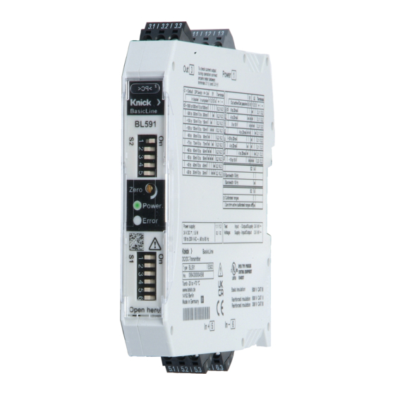
BL590/BL591 2 Product 2.1 Package Contents and Product Identification • Product BL590 / BL591 • Sales packaging (brown folding cardboard box with window over device nameplates) • User manual in three languages (German, English, French) 2.1.1 Nameplates Illustrative example 1 Power supply... -
Page 11: Symbols And Markings
BL590/BL591 2.2 Symbols and Markings Safety Alert Symbols on the BL590 / BL591 and in the User Manual Electric shock hazard! DO NOT touch electrical components! Special conditions and the product’s possible danger points. Read the user manual, observe the specifications, and follow the instructions in the Safety chapter. -
Page 12: Functional Description
BL590/BL591 2.3 Functional Description The input signal is converted into a pulse-width modulated signal and fed into the primary side of a transformer. On the secondary side, the pulse-width signal is converted back into load-indepen- dent current or impressed voltage. - Page 13 BL590/BL591 Block Diagram 1 Input 3 Power supply (reverse polarity protected; polarity is random for supply with direct voltage) 2 Output...
-
Page 14: Commissioning
BL590/BL591 3 Commissioning 3.1 Mounting and Electrical Connection WARNING! Shock potential. For applications with high work- ing voltages, take measures to prevent accidental contact and en- sure sufficient clearance or insulation between adjacent devices. Do not connect the product power supply or apply measuring volt- age until it has been professionally installed. -
Page 15: Terminal Assignment And Dimensions
BL590/BL591 3.2 Terminal Assignment and Dimensions 1.1 Power supply 5.1 Not used 1.2 Power supply 5.2 Positive input 1.3 Not used 5.3 Not used 3.1 Current output (passive/ac- 6.1 Not used tive) 3.2 GND output 6.2 Negative input 3.3 Voltage output 6.3 Not used... -
Page 16: Input Ranges
BL590/BL591 3.3 Input Ranges BL590 Bipolar input Unipolar input Switch Input Input range range resistance terminals S1: 1 … 4 0000 2 MΩ 5.2 / 6.2 –500 … 5 00 V 0 … 5 00 V 0010 2 MΩ 5.2 / 6.2 -450 … 4 50 V 0 … ... -
Page 17: Output Ranges
BL590/BL591 3.4 Output Ranges BL590 / BL591 Input Active out- Passive Output termi- S2: 1 … 3 output nals 5 … 6 Unipolar 0-20 mA 3.1 / 3.2 Unipolar 3.1 / 3.2 4 … 2 0 mA Unipolar 3.3 / 3.2 0 … 1 0 V Unipolar 3.1 / 3.2... -
Page 18: Installation
BL590/BL591 4 Installation 4.1 Input Wiring BL590 BL591 1 Terminal 2 Voltage source... -
Page 19: Output Wiring
BL590/BL591 4.2 Output Wiring The current measurement shown here (3) is for verifying the out- put current without opening the output circuit. Terminals 3.1 and 3.3 are the monitor output. The monitor output can be used for non-disruptive testing of the output current by temporarily connecting a multimeter (to the test jacks), or permanently connecting an isolated display unit. - Page 20 BL590/BL591 Active Current Output with Optional Measurement 1 Test jack 3 Optional current measurement (only DC currents can be correctly measured) 2 Terminal 4 Optional voltage measurement: V is used to verify whether the connected load is within the specified range. The voltage...
- Page 21 BL590/BL591 Voltage Output with Optional Measurement 1 Test jack 3 Optional voltage measurement 2 Terminal...
- Page 22 BL590/BL591 Passive Current Output with Optional Measurement The device is configured for “passive output” (unipolar/bipolar): 0 ... 14 V 1 Test jack 3 Optional current measurement (only DC currents can be cor- rectly measured) 2 Terminal 4 Voltage measurement...
-
Page 23: Operation
BL590/BL591 5 Operation NOTICE! Do not change the measuring range during operation. 5.1 Control Elements (Head Plate) Switch S1 Function (factory setting in bold) Input range 1 … 4 Output range 5 … 6 Switch S2 Active output Passive output... -
Page 24: Test Jacks
BL590/BL591 5.2 Test Jacks WARNING! Shock potential. For applications with high work- ing voltages, take measures to prevent accidental contact and en- sure sufficient clearance or insulation between adjacent devices. Use high-voltage test prods with protection against shock hazards. The test jacks (1) located at the signal terminals above the connect-... -
Page 25: Characteristic Curves
BL590/BL591 5.3 Characteristic Curves Transmission curve with display of the adjustable offset. The device functions linearly with 100 % precision up to 105 % input signal. -
Page 26: Troubleshooting
BL590/BL591 6 Troubleshooting USE CAUTION WHEN CONDUCTING ANY TROUBLESHOOTING. FAIL- URE TO ABIDE BY THE REQUIREMENTS SET FORTH HEREIN MAY RE- SULT IN SERIOUS INJURY OR DEATH, AS WELL AS DAMAGE TO PROP- ERTY. Possible er- Possible causes Notes/solution rors... -
Page 27: Maintenance
BL590/BL591 7 Maintenance The product does not require maintenance. It must not be opened. Cleaning NOTICE! Always de-energize the input and power supply of the device before cleaning it. The product may be cleaned with oil-free compressed air. Storage Observe the specifications for storage temperature and relative... -
Page 28: Decommissioning
If required, send the product in a clean condition and securely packed to your local contact. knick.de ➜ Further information can be found at www.knick.de. 8.2 Disposal The local codes and regulations must be observed when disposing of the product. -
Page 29: Specifications
BL590/BL591 9 Specifications 9.1 Voltage Input Data Input ranges BL590 0 … ( ±)50 V to 0 … ( ±)500 V DC BL591 0 … ( ±)30 mV to 0 … ( ±)1000 mV DC Overload capacity (permanent) BL590 max. ±600 V BL591 max. ±30 V Input resistance 10 kΩ... -
Page 30: Transmission Behavior
5 kHz or 10 kHz, switchable Common-mode rejection ratio BL591 CMRR approx. 150 dB (DC/AC: 50 Hz) T-CMRR approx. 100 dB (1000 V, t = 1 μs) Common-mode rejection ratio BL590 CMRR DC: approx. 150 dB AC 50 Hz: approx. 120 dB Temperature influence BL591 < 50 ppm/K full scale BL590 <... -
Page 31: Isolation
BL590/BL591 9.5 Isolation Galvanic isolation 3-port isolation between input, output, and power supply Test voltage 3.6 kV AC across input and output / power supply 3.6 kV AC across power supply and input / out- Working voltage (basic insu- Pollution degree PD2 lation) in accordance with 500 V... -
Page 32: Product
BL590/BL591 9.7 Product Product name BL590 / BL591 Design Modular housing with screw terminals Housing width 17.5 mm Installation Position Vertical or horizontal Installation Conditions Install the product in a suitable housing (enclosure/distribution box) that ensures pollution degree PD 2 or higher and protects from mechanical impact. - Page 33 BL590/BL591 Betriebsanleitung Universal-Trennverstärker Vor Installation lesen. Für künftige Verwendung aufbewahren. Copyright 2021 • Änderungen vorbehalten www.knick.de Version: 1 • Veröffentlicht am 14.07.2021...
- Page 34 BL590/BL591 Ergänzende Hinweise Die folgenden ergänzenden Hinweise erläutern die Inhalte und den Aufbau von sicherheitsrelevanten Informationen in diesem Dokument. Sicherheitskapitel Im Sicherheitskapitel dieses Dokuments wird ein grundlegendes Sicherheitsverständnis aufgebaut. Es werden allgemeine Gefährdungen aufgezeigt und Strategien zu deren Vermeidung gegeben.
- Page 35 BL590/BL591 Inhaltsverzeichnis 1 Sicherheit ................37 Bestimmungsgemäßer Gebrauch......... 37 Restrisiken..................39 Elektrostatische Entladung............39 2 Produkt................. 40 Lieferumfang und Produktidentifikation ......40 2.1.1 Typschilder ..............40 Symbole und Kennzeichnungen........... 41 Funktionsbeschreibung............42 3 Inbetriebnahme..............44 Montage und elektrischer Anschluss........44 Klemmenbelegung und Abmessungen ......
- Page 36 BL590/BL591 9 Technische Daten..............60 Eingangsdaten Spannung ............60 Ausgangsdaten................60 Übertragungsverhalten ............61 Hilfsenergie (Power)..............61 Isolation ..................62 Konformität ................... 62 Produkt ................... 63 Umgebungsbedingungen............63...
-
Page 37: Sicherheit
Messung von Spannungen und der Messung von Strömen via Shunt-Widerstand. Die Umschaltung der Messberei- che erfolgt kalibriert über DIP-Schalter. • BL590 zur Spannungsmessung bis (±)50 … ( ±)500 V DC • BL591 zur Strommessung via Shunt-Widerstand mit einem Spannungseingang (DC) von (±)30 … ( ±)1000 mV DC... - Page 38 BL590/BL591 Das jeweilige Eingangssignal wird am Ausgang als Normsignal 0 … 2 0 mA, 4 … 2 0 mA bzw. 0 … 1 0 V oder als bipolares Ausgangssi- gnal -20 … 2 0 mA bzw. -10 … 1 0 V abgebildet. Der Nullpunkt kann über ein zuschaltbares Potentiometer angepasst werden.
-
Page 39: Restrisiken
BL590/BL591 1.2 Restrisiken Das Produkt ist nach den anerkannten sicherheitstechnischen Regeln der Technik entwickelt und gefertigt. BL590 / BL591 wurde einer internen Risikobeurteilung unterzogen. Dennoch können nicht alle Risiken hinreichend vermindert werden und es bestehen folgende Restrisiken. Berührungsgefährliche Spannungen. Bei Anwendungen mit hohen Arbeitsspannungen genügend Abstand bzw. -
Page 40: Produkt
BL590/BL591 2 Produkt 2.1 Lieferumfang und Produktidentifikation • Produkt BL590 / BL591 • Verkaufsverpackung (Faltschachtel braun mit Sichtfenster auf Gerätetypenschilder) • 3-sprachige Betriebsanleitung (deutsch, englisch, französisch) 2.1.1 Typschilder Beispieldarstellung 1 Hilfsenergie 6 UKCA-Kennzeichnung 2 Prüfspannung 7 UL-Kennzeichnung 3 Herstellername 8 Isolation... -
Page 41: Symbole Und Kennzeichnungen
BL590/BL591 2.2 Symbole und Kennzeichnungen Warnsymbole auf dem BL590 / BL591 und in der Betriebsanleitung Warnung vor gefährlicher elektrischer Spannung bei Berührung elektrischer Bauteile! Besondere Bedingungen und mögliche Gefahrenstellen des Produkts! Lesen Sie die Betriebsanleitung, beachten Sie die technischen Daten und befolgen Sie die Hinweise im Kapitel Sicherheit. -
Page 42: Funktionsbeschreibung
BL590/BL591 2.3 Funktionsbeschreibung Das Eingangssignal wird in ein pulsweitenmoduliertes Signal umgesetzt und der Primärseite eines Transformators zugeführt. Auf der Sekundärseite wird das Pulsweitensignal in eingeprägten Strom bzw. aufgeprägte Spannung rückgewandelt. Die 3-Port-Trennung trägt zu einer unverfälschten Übertragung der Messsignale bei. Durch die verstärkte Isolation nach EN 61140 sorgt die sichere Trennung für den Schutz von Personen vor elektrischem... - Page 43 BL590/BL591 Prinzipschaltbild 1 Eingang 3 Hilfsenergie (verpolungssicher; bei Versorgung mit Gleichspan- nung ist die Polarität beliebig) 2 Ausgang...
-
Page 44: Inbetriebnahme
BL590/BL591 3 Inbetriebnahme 3.1 Montage und elektrischer Anschluss WARNUNG! Berührungsgefährliche Spannungen. Bei Anwen- dungen mit hohen Arbeitsspannungen auf genügend Abstand bzw. Isolation zu Nebengeräten und Berührungsschutz achten. Erst nach der fachgerechten Installation das Produkt mit Hilfsenergie versorgen und mit Messspannung beaufschlagen. -
Page 45: Klemmenbelegung Und Abmessungen
BL590/BL591 3.2 Klemmenbelegung und Abmessungen 1.1 Hilfsenergie 5.1 Nicht belegt 1.2 Hilfsenergie 5.2 Eingang positiv 1.3 Nicht belegt 5.3 Nicht belegt 3.1 Ausgang Strom (passiv/aktiv) 6.1 Nicht belegt 3.2 Ausgang GND 6.2 Eingang negativ 3.3 Ausgang Spannung 6.3 Nicht belegt Bei Versorgung mit Gleichspannung ist die Polarität beliebig. -
Page 46: Eingangsbereiche
BL590/BL591 3.3 Eingangsbereiche BL590 Nr. Eingangsbereich Eingangsbereich Schalter Eingangs- Eingangs- bipolar unipolar widerstand klemmen S1: 1 … 4 0000 2 MΩ 5.2 / 6.2 –500 … 5 00 V 0 … 5 00 V 0010 2 MΩ 5.2 / 6.2 –450 … 4 50 V 0 … ... -
Page 47: Ausgangsbereiche
BL590/BL591 3.4 Ausgangsbereiche BL590 / BL591 Nr. Eingang Ausgang Ausgang Ausgangs- S1: 5 … 6 S2: 1 … 3 aktiv passiv klemmen Unipolar 0-20 mA 3.1 / 3.2 Unipolar 3.1 / 3.2 4 … 2 0 mA Unipolar 3.3 / 3.2 0 … 1 0 V Unipolar 3.1 / 3.2... -
Page 48: Installation
BL590/BL591 4 Installation 4.1 Eingangsbeschaltung BL590 BL591 1 Klemme 2 Spannungsquelle... -
Page 49: Ausgangsbeschaltungen
BL590/BL591 4.2 Ausgangsbeschaltungen Die hier dargestellte Strommessung (3) dient der Überprüfung des Ausgangsstroms ohne Öffnen des Ausgangskreises. Die Klemmen 3.1 und 3.3 stellen den Monitorausgang dar. Am Monitorausgang kann der Ausgangsstrom unterbrechungsfrei mit einem Multimeter (an den Prüfbuchsen) temporär kontrolliert oder ein potentialfreies Anzeigegerät dauerhaft angeschlossen... - Page 50 BL590/BL591 Stromausgang aktiv mit optionaler Messung 1 Prüfbuchse 3 Optionale Strommessung (nur DC-Ströme können korrekt gemessen werden) 2 Klemme 4 Optionale Spannungsmessung: V dient der Prüfung, ob die angeschlossene Bürde im spezifizierten Bereich liegt. Die Spannung muss ≤ 12 V sein.
- Page 51 BL590/BL591 Spannungsausgang mit optionaler Messung 1 Prüfbuchse 3 Optionale Spannungsmessung 2 Klemme...
- Page 52 BL590/BL591 Stromausgang passiv mit optionaler Messung Das Gerät ist für „Ausgang passiv“ konfiguriert (unipolar/bipolar). 0 ... 14 V 1 Prüfbuchse 3 Optionale Strommessung (nur DC-Ströme können korrekt ge- messen werden) 2 Klemme 4 Spannungsmessung...
-
Page 53: Betrieb
BL590/BL591 5 Betrieb ACHTUNG! Während des Betriebs keine Bereichsumschaltung vornehmen. 5.1 Bedienelemente (Kopfplatte) Schalter S1 Funktion (Werkseinstellung fett gedruckt) Eingangsbereich 1 … 4 Ausgangsbereich 5 … 6 Schalter S2 Ausgang aktiv Ausgang passiv Spannungsausgang Stromausgang Nicht unterstützt Nicht unterstützt Grenzfrequenz 10 Hz Grenzfrequenz 5 kHz... -
Page 54: Prüfbuchsen
BL590/BL591 5.2 Prüfbuchsen WARNUNG! Berührungsgefährliche Spannungen. Bei An- wendungen mit hohen Arbeitsspannungen auf genügend Abstand bzw. Isolation zu Nebengeräten und auf Berührungsschutz achten. Hochspannungssichere Prüfspitzen mit Berührungsschutz verwen- den. Die Prüfbuchsen (1), die sich jeweils oberhalb der Anschlussdrähte an der entsprechenden Signalklemme befinden, dienen der... -
Page 55: Kennlinienverläufe
BL590/BL591 5.3 Kennlinienverläufe Übertragungskennlinie mit Darstellung des einstellbaren Offsets. Bis 105 % Aussteuerung arbeitet das Gerät linear mit voller Genauigkeit. -
Page 56: Störungsbehebung
BL590/BL591 6 Störungsbehebung Bei der Störungsbehebung ist stets Sorgfalt geboten. Die Nichtein- haltung der hier beschriebenen Anforderungen kann schwere Ver- letzungen von Personen und/oder Sachschäden zur Folge haben. - Page 57 BL590/BL591 Möglicher Mögliche Ursache Hinweise/Abhilfe Fehler LED-Anzeige Anschluss der Den korrekten Anschluss aller Leitungen Error Rot Leitungen prüfen. Hilfsenergie Die Hilfsenergie prüfen. Wenn die Power- LED grün leuchtet, ist Hilfsenergie vorhan- den. Eingangssignal Prüfen, ob das Eingangssignal tatsächlich anliegt. Ausgangssignal Den Spannungsausgang z.
-
Page 58: Wartung
BL590/BL591 7 Wartung Das Produkt ist wartungsfrei. Es darf nicht geöffnet werden. Reinigung ACHTUNG! Vor der Reinigung den Eingang und die Hilfsenergie des Geräts spannungsfrei schalten. Das Produkt kann mit ölfreier Druckluft gereinigt werden. Lagerung Die Angaben zu den Lagertemperaturen und der relativen Feuchte... -
Page 59: Außerbetriebnahme
8.1 Rücksendung Das Produkt bei Bedarf in gereinigtem Zustand und sicher verpackt an die zuständige lokale Vertretung senden. knick.de ➜ Weitere Informationen sind auf www.knick.de verfügbar. 8.2 Entsorgung Zur sachgemäßen Entsorgung des Produkts sind die lokalen Vorschriften und Gesetze zu befolgen. -
Page 60: Technische Daten
BL590/BL591 9 Technische Daten 9.1 Eingangsdaten Spannung Eingangsbereiche BL590 0 … ( ±)50 V bis 0 … ( ±)500 V DC BL591 0 … ( ±)30 mV bis 0 … ( ±)1000 mV DC Überlastbarkeit (dauernd) BL590 max. ±600 V BL591 max. ±30 V Eingangswiderstand 10 kΩ... -
Page 61: Übertragungsverhalten
Grenzfrequenz 10 Hz: 200 ms Grenzfrequenz 5 kHz oder 10 kHz, umschaltbar Gleichtaktunterdrückung BL591 CMRR ca. 150 dB (DC/AC: 50 Hz) T-CMRR ca. 100 dB (1000 V, t = 1 µs) Gleichtaktunterdrückung BL590 CMRR DC: ca. 150 dB AC 50 Hz: ca. 120 dB Temperatureinfluss BL591 < 50 ppm/K vom Endwert BL590 < 80 ppm/K vom Endwert 9.4 Hilfsenergie (Power) -
Page 62: Isolation
BL590/BL591 9.5 Isolation Galvanische Trennung 3-Port-Trennung zwischen Eingang, Ausgang und Hilfsenergie Prüfspannung 3,6 kV AC Eingang gegen Ausgang und Hilfsenergie 3,6 kV AC Hilfsenergie gegen Eingang und Ausgang Arbeitsspannung Verschmutzungsgrad PD2 (Basisisolierung) gemäß 500 V IEC 61010-1, EN 61010-1 und Überspannungskategorie CAT II (OV II) UL 61010-1 zwischen allen 500 V... -
Page 63: Produkt
BL590/BL591 9.7 Produkt Produktname BL590 / BL591 Bauform Anreihgehäuse mit Schraubklemmen Gehäusebreite 17,5 mm Einbaulage Senkrecht oder waagerecht Einbaubedingung Das Produkt in ein geeignetes Gehäuse (Schaltschrank / Verteilerkasten) einbauen, das den Verschmutzungsgrad PD 2 oder besser gewährleistet und vor mechanischer Einwirkung durch Schlag schützt. Das Gehäuse darf nur mit einem Werkzeug (Schlüssel) - Page 65 BL590/BL591 Manuel utilisateur Convertisseurs universels Lire avant l'installation. Conserver pour une utilisation ultérieure. Copyright 2021 • Sous réserve de modifications www.knick.de Version: 1 • Publié le 14/07/2021...
- Page 66 BL590/BL591 Remarques complémentaires Les remarques complémentaires suivantes détaillent le contenu et la structure des informations relatives à la sécurité contenues dans ce document. Chapitre Sécurité Les connaissances fondamentales relatives à la sécurité sont déve- loppées dans le chapitre Sécurité de ce document. Il contient l'identification des dangers généraux et le détail des stratégies per-...
- Page 67 BL590/BL591 Table des matières 1 Sécurité................. 69 Utilisation conforme ..............69 Risques résiduels ................. 70 Décharge électrostatique ............71 2 Produit.................. 72 Fourniture et identification du produit....... 72 2.1.1 Plaques signalétiques..........72 Symboles et marquages ............73 Description fonctionnelle ............73 3 Mise en service..............
- Page 68 BL590/BL591 9 Caractéristiques techniques ..........91 Données d'entrée tension............91 Données de sortie............... 91 Caractéristique de transmission ..........92 Alimentation auxiliaire (Power)..........92 Isolation ..................93 Conformité ..................93 Produit .................... 94 Conditions ambiantes ............... 94...
-
Page 69: Sécurité
Le changement de la plage de mesure se fait sous cali- brage par switch DIP. • BL590 pour la mesure de tensions jusqu'à (±)50 … ( ±)500 V DC • BL591 pour la mesure de courants via une résistance shunt avec une entrée de tension (DC) de (±)30 … ... -
Page 70: Risques Résiduels
1.2 Risques résiduels Le produit est conçu et fabriqué selon les règles techniques de sé- curité reconnues. BL590 / BL591 a fait l'objet d'une évaluation in- terne des risques. Il est néanmoins impossible de minimiser tous les risques et les risques résiduels suivants subsistent. -
Page 71: Décharge Électrostatique
BL590/BL591 Tensions dangereuses en cas de contact. Dans le cas d'applications avec des tensions de service élevées, ob- server une distance suffisante ou assurer une isolation avec les ap- pareils voisins et veiller à la protection contre les contacts ! Le produit doit toujours être utilisé dans une armoire fermée. Ne ja- mais toucher le produit pendant son fonctionnement. -
Page 72: Produit
BL590/BL591 2 Produit 2.1 Fourniture et identification du produit • Produit BL590 / BL591 • Emballage de vente (boîte pliante marron laissant apparaître la plaque signalétique de l'appareil) • Manuel utilisateur rédigé en 3 langues (allemand, anglais, fran- çais) 2.1.1 Plaques signalétiques... -
Page 73: Symboles Et Marquages
BL590/BL591 2.2 Symboles et marquages Symboles d'avertissement sur le BL590 / BL591 et dans le manuel utilisateur Tension électrique dangereuse en cas de contact avec les composants électriques ! Conditions particulières et endroits dangereux éventuels du produit ! Lire le manuel utilisateur, tenir compte des caractéristiques techniques et respecter les consignes contenues dans le chapitre Sécurité ! - Page 74 BL590/BL591 Séparation 3 ports des trois circuits : entrées, sorties et alimentation 1 Entrées 3 Alimentation 2 Sorties...
- Page 75 BL590/BL591 Schéma de principe 1 Entrée 3 Alimentation (protégée contre l'inversion de la polarité ; dans le cas d'une alimentation à ten- sion continue, la polarité n'a pas d'importance) 2 Sortie...
-
Page 76: Mise En Service
BL590/BL591 3 Mise en service 3.1 Montage et raccordement électrique AVERTISSEMENT ! Tensions dangereuses en cas de contact. Dans le cas d'applications avec des tensions de service élevées, ob- server une distance suffisante ou assurer une isolation avec les ap- pareils voisins et veiller à... -
Page 77: Correspondance Des Bornes Et Dimensions
BL590/BL591 3.2 Correspondance des bornes et dimensions 1.1 Alimentation 5.1 Libre 1.2 Alimentation 5.2 Entrée positive 1.3 Libre 5.3 Libre 3.1 Sortie courant (passive/active) 6.1 Libre 3.2 Sortie GND 6.2 Entrée négative 3.3 Sortie tension 6.3 Libre Dans le cas d'une alimentation à tension continue, la polarité n'a pas d'impor- tance. -
Page 78: Plages D'entrée
BL590/BL591 3.3 Plages d'entrée BL590 N° Plage d'entrée Plage d'entrée Commu- Résistance Bornes bipolaire unipolaire tateur d'entrée d'entrée S1 : 1 … 4 0.000 2 MΩ 5.2 / 6.2 –500 … 5 00 V 0 … 5 00 V 0.010 2 MΩ 5.2 / 6.2 –450 … 4 50 V 0 … ... -
Page 79: Plages De Sortie
BL590/BL591 3.4 Plages de sortie BL590 / BL591 N° Entrée Sortie Sortie Bornes S1 : 5 … 6 S2 : 1 … 3 active passive de sortie 1 Unipolaire 0-20 mA 3.1 / 3.2 2 Unipolaire 3.1 / 3.2 4 … 2 0 mA 3 Unipolaire 3.3 / 3.2 0 … 1 0 V 4 Unipolaire 3.1 / 3.2... -
Page 80: Installation
BL590/BL591 4 Installation 4.1 Circuit d'entrée BL590 BL591 1 Borne 2 Source de tension 4.2 Circuits de sortie La mesure de courant (3) représentée ici sert à vérifier le courant de sortie sans ouvrir le circuit de sortie. Les bornes 3.1 et 3.3 repré- sentent la sortie Monitor. - Page 81 BL590/BL591 Sortie de courant active avec mesure en option 1 Prise d'essai 3 Mesure de courant en option (seuls les courants DC peuvent être mesurés correctement) 2 Borne 4 Mesure de tension en option : V permet de vérifier si la charge connectée se trouve dans la...
- Page 82 BL590/BL591 Sortie de tension avec mesure en option 1 Prise d'essai 3 Mesure de tension en option 2 Borne...
- Page 83 BL590/BL591 Sortie de courant passive avec mesure en option L'appareil est configuré pour une « sortie passive » (unipolaire/bipo- laire). 0 ... 14 V 1 Prise d'essai 3 Mesure de courant en option (seuls les courants DC peuvent être mesurés correctement) 2 Borne...
-
Page 84: Fonctionnement
BL590/BL591 5 Fonctionnement AVIS ! Veiller à n'effectuer aucun changement de plage en cours de fonctionnement. 5.1 Éléments de commande (plaque supérieure) Commutateur S1 Fonction (réglage d'origine en gras) Plage d'entrée 1 … 4 Plage de sortie 5 … 6... -
Page 85: Prises D'essai
BL590/BL591 5.2 Prises d'essai AVERTISSEMENT ! Tensions dangereuses en cas de contact. Dans le cas d'applications avec des tensions de service élevées, ob- server une distance suffisante ou assurer une isolation avec les ap- pareils voisins et veiller à la protection contre les contacts. Utiliser des pointes pourvues d'un coupe-circuit à... -
Page 86: Caractéristiques
BL590/BL591 5.3 Caractéristiques Caractéristique de transmission avec représentation de l'offset ré- glable. Jusqu'à une modulation de 105 %, l'appareil fonctionne de manière linéaire avec une précision optimale. -
Page 87: Dépannage
BL590/BL591 6 Dépannage Il convient toujours de faire preuve de prudence lors de l’élimina- tion des défauts. Le non-respect des exigences décrites dans le pré- sent document peut entraîner des blessures corporelles graves et/ ou des dommages matériels. - Page 88 BL590/BL591 Défaut possible Cause pos- Remarques/remède sible Affichage LED Er- Raccordement Contrôler le raccordement correct de tous ror rouge des câbles les câbles. Alimentation Contrôler l'alimentation auxiliaire. Quand la LED Power est allumée, le convertisseur est alimenté. Entrée de si- Contrôler la présence réelle du signal...
-
Page 89: Entretien
BL590/BL591 7 Entretien Le produit ne nécessite pas d'entretien. Il ne doit pas être ouvert. Nettoyage AVIS ! Avant le nettoyage, mettre hors tension l'entrée et l'alimen- tation du produit. Le produit peut être nettoyé avec de l'air comprimé sans huile. -
Page 90: Mise Hors Service
BL590/BL591 8 Mise hors service Le produit doit être mis hors service et protégé contre toute remise en service dans les cas suivants : • Endommagement visible du produit • Défaillance du fonctionnement électrique • Stockage de longue durée à des températures non comprises dans la plage de température spécifiée... -
Page 91: Caractéristiques Techniques
BL590/BL591 9 Caractéristiques techniques 9.1 Données d'entrée tension Plages d'entrée BL590 De 0 … ( ±)50 V à 0 … ( ±)500 V DC BL591 De 0 … ( ±)30 mV à 0 … ( ±)1000 mV DC Capacité de surcharge (continue) BL590 max. ±600 V BL591 max. -
Page 92: Caractéristique De Transmission
Réjection en mode commun BL591 CMRR env. 150 dB (DC/AC : 50 Hz) T-CMRR env. 100 dB (1000 V, t = 1 µs) Réjection en mode commun BL590 CMRR DC : env. 150 dB AC 50 Hz : env. 120 dB Influence de la température BL591 < 50 ppm/K de la valeur finale BL590 < 80 ppm/K de la valeur finale... -
Page 93: Isolation
BL590/BL591 9.5 Isolation Isolation galvanique Isolation 3 ports entre entrée, sortie et alimentation Tension d'essai 3,6 kV AC entre entrée et sortie/ali- mentation 3,6 kV AC entre entrée et sortie et ali- mentation Tension de service (isolation de base) Degré de pollution PD2 selon la norme IEC 61010-1, EN 500 V... -
Page 94: Produit
BL590/BL591 9.7 Produit Nom du produit BL590 / BL591 Modèle Boîtier série avec bornes à vis Largeur du boîtier 17,5 mm Position de montage Vertical ou horizontal Conditions d'installation Installer le produit dans un boîtier adapté (armoire électrique/coffret de raccorde- ment) qui garantit un degré de pollution PD 2 ou supérieur et le protège des chocs... - Page 95 BL590/BL591 Notes...
- Page 96 Knick Elektronische Messgeräte GmbH & Co. KG Headquarters Beuckestraße 22 • 14163 Berlin Germany Phone: +49 30 80191-0 Fax: +49 30 80191-200 info@knick.de www.knick.de Local Contacts www.knick-international.com Copyright 2021 • Subject to change Version 1 • This document was published on July 14, 2021.
Need help?
Do you have a question about the BL590 and is the answer not in the manual?
Questions and answers