Table of Contents
Advertisement
Available languages
Available languages
Quick Links
Advertisement
Table of Contents

Related Manuals for cias PYTHAGORAS3

Summary of Contents for cias PYTHAGORAS3
- Page 1 PYTHAGORAS3 Barriera Multi-tecnologia Microonde e infrarosso per protezioni esterne Manuale di Installazione Multi-technology Barrier Microwave and Infrared Installation Manual Edizione / Edition 1.0 20MACIE0197...
-
Page 2: Table Of Contents
CIAS Elettronica S.r.l. Ed. 1.0 INDICE DESCRIZIONE ..................................... 3 ...................................... 3 ESCRIZIONE INSTALLAZIONE ....................................4 .................................. 4 ONTAGGIO DELLE UNITÀ .................................... 6 UMERO DI RATTE ’I ..............................7 VVERTENZE PER L NSTALLAZIONE .................................. 7 ONDIZIONI DEL ERRENO ..................................7... - Page 3 CIAS Elettronica S.r.l. Ed. 1.0 INDEX DESCRIPTION ....................................40 ....................................40 ESCRIPTION INSTALLATION ....................................41 ................................... 41 OUNTING OF THE ................................... 43 UMBER OF ONES ..................................44 NSTALLATION DVICE ..................................44 ROUND ONDITIONS ....................................... 44 BSTACLES MW S ............................45...
-
Page 4: Descrizione
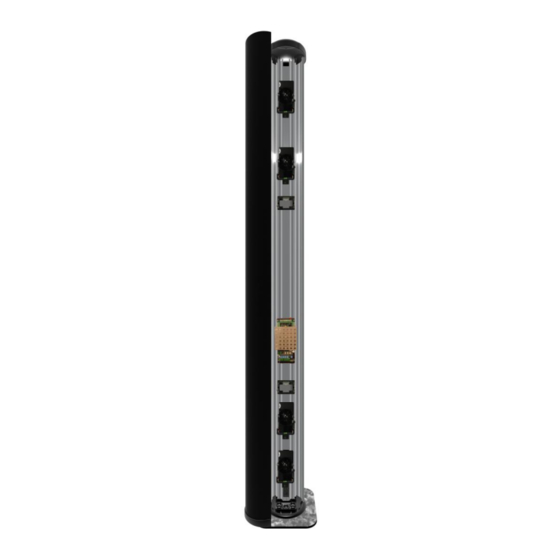
1 DESCRIZIONE 1.1 Descrizione PYTHAGORAS3 è una barriera multi tecnologia per protezioni volumetriche perimetrali esterne. La barriera è in grado di rilevare la presenza di un corpo che si muove all’interno di un campo sensibile instauratosi tra il Trasmettitore (TX) e il Ricevitore (RX). -
Page 5: Installazione
CIAS Elettronica S.r.l. Ed. 1.0 2 INSTALLAZIONE 2.1 Montaggio delle unità Per il montaggio delle due unità (TX e RX) fissare la base di sostegno a terra. Aprire ogni singola colonna partendo dal coperchio superiore. Rimuovere le viti con l’aiuto di un cacciavite. - Page 6 CIAS Elettronica S.r.l. Ed. 1.0 Nella parte superiore di ciascuna colonna sono presenti due interruttori (tamper) in serie. Quello laterale segnala la rimozione del coperchio superiore. Quello centrale segnala invece la pressione sul coperchio ed è quindi indicato per rivelare tentativi di scavalcamento.
-
Page 7: Numero Di Tratte
CIAS Elettronica S.r.l. Ed. 1.0 2.2 Numero di Tratte Dovendo progettare la protezione con barriere volumetriche di un perimetro chiuso, oltre alle normali considerazioni di suddivisione del perimetro in un certo numero di tratte che tengano conto delle necessità gestionali dell'intero impianto, occorre ricordare che è sempre preferibile installare un numero di tratte pari. -
Page 8: Avvertenze Per L'installazione
è consigliabile che il corridoio tra esse non sia inferiore ai 5 m. in quanto il loro movimento potrebbe creare dei disturbi. Occorre notare che utilizzando uno degli scenari “AND” successivamente descritti al capitolo 4, Pythagoras3 può essere installato anche in corridoi di dimensioni inferiori a 5 m. -
Page 9: Ampiezza Dei Fasci Sensibili Amw
[m] Figura 3 Larghezza della zona sensibile a metà tratta per PYTHAGORAS3 100-160 (campo libero) 2.7 Lunghezza delle Zone Morte in prossimità degli apparati La lunghezza delle Zone Morte in prossimità degli apparati è in funzione sia della distanza dell'apparato stesso dal suolo, sia della sensibilità... -
Page 10: Collegamenti
CIAS Elettronica S.r.l. Ed. 1.0 3 COLLEGAMENTI 3.1 Morsettiere, connettori e Funzionalità dei Circuiti 3.1.1 Circuito di controllo Trasmettitore TERMINAZIONE DI LINEA RS 485 JP2 LED GUASTO TAMPER SYNC Figura 5 Disposizione topografica dei componenti nel circuito di controllo Tx... - Page 11 CIAS Elettronica S.r.l. Ed. 1.0 CONNETTORE J2 TRASMETTITORE Simbolo Funzione Massa per Oscillatore a MW Collegamento per Oscillatore a MW Massa per Oscillatore a MW CONNETTORE J3 TRASMETTITORE Simbolo Funzione 1-2-3-5-8-9-10-11- N.C. Non Connesso 14-15 Massa +13,8 Tensione di Alimentazione (13,8 V )
-
Page 12: Circuito Di Controllo Ricevitore
CIAS Elettronica S.r.l. Ed. 1.0 3.1.2 Circuito di controllo Ricevitore ALLARME GUASTO TAMPER Figura 6 Disposizione topografica dei componenti nel circuito di elaborazione Rx Nelle seguenti tabelle sono indicate le funzioni delle morsettiere presenti sulla scheda PYTHAGORAS3 RX: MORSETTIERA MS2... - Page 13 CIAS Elettronica S.r.l. Ed. 1.0 CONNETTORE J2 RICEVITORE Simbolo Funzione Massa per Rivelatore a Microonde Collegamento per Rivelatore a Microonde (Detector) Massa per Rivelatore a Microonde CONNETTORE J3 RICEVITORE Simbolo Funzione 1-2-3-5-8-10-11-13- N.C. Non Connesso 15-16 Massa +13,8 Tensione di Alimentazione (13,8 V )
-
Page 14: Circuito Tx E Rx Ir
CIAS Elettronica S.r.l. Ed. 1.0 SELETTORE DI FUNZIONI SUL RICEVITORE Simbolo Funzione Posizione 1 = Allineamento Barriera MW Posizione 2 = Acquisizione parametri Barriera MW (Canale, Valore di Campo, Indicazione della Qualità dell’Allineamento) Posizione 3 = Walk Test Barriera MW, acquisizione Soglie di sensibilità... -
Page 15: Circuito Di Interfaccia Trasmettitore
CIAS Elettronica S.r.l. Ed. 1.0 3.1.4 Circuito di Interfaccia Trasmettitore +13,8V DISQ Power IR High DISQ IN AL IN AL DISQ DISQ +13,8V IR1 Low IR2 Low Figura 7 Disposizione topografica dei componenti nel circuito di interfaccia Tx MORSETTIERA MS5 (POWER) INTERFACCIA TRASMETTITORE... -
Page 16: Circuito Di Interfaccia Ricevitore
CIAS Elettronica S.r.l. Ed. 1.0 3.1.5 Circuito di Interfaccia Ricevitore +13,8V DISQ Power IR High DISQ IN AL IN AL DISQ DISQ +13,8V IR1 Low IR2 Low Figura 8 Disposizione topografica dei componenti nel circuito di interfaccia Rx MORSETTIERA MS5 (POWER) INTERFACCIA RICEVITORE... -
Page 17: Collegamento All'alimentazione Principale
PYTHAGORAS3 100 PYTHAGORAS3 160 Nota: utilizzando lo stesso cavo per alimentare più barriere Pythagoras3 le distanze indicate devono essere divise per il numero di barriere collegate 3.2.1 Collegamento all’alimentazione per il Riscaldatore L’alimentazione relativa al sistema di riscaldamento, deve essere connessa direttamente all’apposita morsettiera (HEATER) di ogni sensore IR e deve essere realizzata con una linea di... -
Page 18: Collegamento Alla Centrale
CIAS Elettronica S.r.l. Ed. 1.0 3.3 Collegamento alla Centrale Le connessioni alla Centrale di elaborazione devono essere effettuate mediante cavi schermati. 3.3.1 Contatti di segnalazione: Le uscite degli apparati sono costituite: sul ricevitore da 3 contatti normalmente chiusi liberi da potenziale, per la segnalazione dei seguenti stati: ... -
Page 19: Connessioni Per Sincronismo
CIAS Elettronica S.r.l. Ed. 1.0 3.3.2 Connessioni per Sincronismo Per effettuare il Sincronismo tra due Trasmettitori occorre connettere tra loro i morsetti 8 “SYNC” ed i morsetti 7 “GND” della morsettiera MS2 dei due Trasmettitori. È Inoltre necessario selezionare un Trasmettitore come “Master” e l’altro come “Slave”... -
Page 20: Linea Seriale Rs-485
Ed. 1.0 3.4 Linea Seriale RS-485 3.4.1 Interfaccia Linea Seriale RS-485 / 232 Sia il ricevitore che il trasmettitore della barriera PYTHAGORAS3, sono dotati, ciascuno, di una interfaccia seriale standard RS-485. I parametri di comunicazione sono i seguenti: Modo: Asincrono Half-Duplex Velocità:... -
Page 21: Collegamento Da Accesso Remoto
In questo caso i dispositivi di campo, sono meno di 32 ma possono essere dislocati su una linea lunga 3600 mt. Figura 10 3.5 Collegamento da Accesso Remoto Per interfacciare il modem (per linea telefonica commutata con velocità di 9600 b/s) alle barriere PYTHAGORAS3 oltre alla conversione RS485/RS232 occorre la conversione cross mostrata di seguito: Figura 11 Manuale di Installazione... -
Page 22: Allineamento E Verifica Microonda
4 ALLINEAMENTO E VERIFICA MICROONDA 4.1 Allineamento e Verifica Le barriere PYTHAGORAS3 sono dotate di un sistema di allineamento elettronico, di un sistema di regolazione dei parametri di lavoro e di un sistema di test, che rendono particolarmente semplici ed efficaci sia le operazioni di installazione che di manutenzione periodica, senza la necessità... - Page 23 CIAS Elettronica S.r.l. Ed. 1.0 3) Predisporre uno dei 16 canali di modulazione disponibili ruotando il commutatore esadecimale “SW3” in una posizione compresa tra 0 e F. L’utilizzo di un canale di modulazione piuttosto di un altro non altera il funzionamento della barriera, è...
-
Page 24: Operazioni Sul Ricevitore
(per esempio passando una mano davanti all’antenna del trasmettitore), in questo modo una sola persona potrà facilmente ed efficacemente effettuare l’allineamento delle barriere PYTHAGORAS3. g. Ottenuto il miglior allineamento (quindi il massimo segnale disponibile) bloccare il movimento orizzontale sia sul Ricevitore sia sul Trasmettitore. - Page 25 CIAS Elettronica S.r.l. Ed. 1.0 i. Sbloccare il movimento verticale della testa trasmittente (Tx) ed effettuare le operazioni descritte per l’orientamento verticale del Ricevitore, invece di premere il pulsante S1 del ricevitore oscurare momentaneamente l’emissione di radiofrequenza del trasmettitore. Al termine delle operazioni, bloccare il movimento verticale sia sul Ricevitore sia sul Trasmettitore.
- Page 26 CIAS Elettronica S.r.l. Ed. 1.0 È possibile impostare valori da 0 a F. Più alto è il valore impostato, maggiore è la sensibilita. Se si desidera diminuire la sensibilita impostare un valore più basso. Se si desidera aumentare la sensibilità impostare un valore più alto.
- Page 27 CIAS Elettronica S.r.l. Ed. 1.0 6 Portando il commutatore di funzione SW1 in posizione 8 è possibile leggere e/o modificare il Numero di Tratta. Modifica del numero di tratta: selezionare un numero da 1 a 99 sugli appositi commutatori SW2 (decine) e SW3 (unità).
- Page 28 CIAS Elettronica S.r.l. Ed. 1.0 Scenario “9” : AND con Filtro 2 tecnologie Scegliendo questo scenario si ha la produzione di allarme se una coppia di barriere di diversa tecnologia, a prescindere dalla sequenza (priorità), raggiunge la condizione di allarme.
- Page 29 CIAS Elettronica S.r.l. Ed. 1.0 Scenario “C” : AND con Antiscavalcamento Scegliendo questo scenario si ha la produzione di allarme se almeno una coppia di barriere raggiunge la condizione di allarme o se il solo IR Alto (Antiscavalcamento) raggiunge una condizione di allarme.
-
Page 30: Allineamento E Verifica Con Software
Nota importante: La segnalazione all’elaboratore di uno stato di Disqualifica da parte di una qualsiasi barriera IR tra le tre possibili presenti in ciascuna barriera Pythagoras3, produce oltre che una segnalazione di guasto con l’attivazione dell’apposito relè sul Ricevitore, anche una riconfigurazione automatica della barriera MW e del sensore Doppler, portando sulla barriera la sensibilità... -
Page 31: Allineamento E Verifica Infrarosso
CIAS Elettronica S.r.l. Ed. 1.0 5 ALLINEAMENTO E VERIFICA INFRAROSSO 5.1 Selezione Canali Per evitare interferenze reciproche fra barriere installate nello stesso sito, le barriere sono impostabili con otto diverse frequenze (canali). Ciascuna Newton ha la possibilità di appartenere a due gruppi, gruppo A o gruppo B, ed ogni gruppo può... - Page 32 CIAS Elettronica S.r.l. Ed. 1.0 2. Stacks di due Newton3: In questo caso è richiesta la sincronizzazione dei due trasmettitori appartenenti allo stesso gruppo per mezzo di fili*. Non è richiesta nessuna sincronizzazione dei ricevitori. 3. Stacks di tre Newton3: In questo caso è...
-
Page 33: Allineamento Ottico
CIAS Elettronica S.r.l. Ed. 1.0 5.2 Allineamento Ottico Dopo aver alimentato sia il Trasmettitore sia il Ricevitore, la prima operazione da eseguire è un allineamento ottico. Asse ottico Trasmettitore Ricevitore L’allineamento ottico consiste nel far coincidere gli assi ottici dei moduli ricevitore e trasmettitore. -
Page 34: Allineamento Elettronico
CIAS Elettronica S.r.l. Ed. 1.0 5.3 Allineamento Elettronico Dopo aver effettuato l’Allineamento Ottico è necessario ottimizzare l’allineamento, utilizzando il sistema elettronico incorporato. È possibile effettuare l’ottimizzazione del livello del segnale ricevuto utilizzando il tester, indicazioni sonore e visive proporzionali al segnale. Tali indicazioni sono attive sia sul trasmettitore che sul ricevitore dei modelli Newton3 120 e Newton3 200. -
Page 35: Scelta Della Modalità Operativa
CIAS Elettronica S.r.l. Ed. 1.0 5.4 Scelta della modalità operativa Le barriere Newton3 120 e Newton3 200 possono funzionare in 2 diverse modalità. Modalità “AND GATE” : L’allarme viene attivato con l’interruzione simultanea dei 4 raggi ad infrarosso emessi dai due moduli ottici, Modalità... -
Page 36: Modalità Operative
CIAS Elettronica S.r.l. Ed. 1.0 5.5 Modalità Operative Modalità “AND” : Modalità “OR” : Interruzione Interruzione di uno dei simultanea di 2 moduli 2 moduli ottici per ottici per l’allarme l’allarme intrusione. intrusione 5.6 Tempo di Interruzione Il Tempo di Interruzione, regolabile mediante l’apposito commutatore posto sul modulo elettronico Ricevitore, può... -
Page 37: Controllo Finale
CIAS Elettronica S.r.l. Ed. 1.0 5.8 Controllo finale Ad installazione completata eseguire le seguenti verifiche: In modalità AND GATE: verificare che l’attraversamento della barriera produca una segnalazione di allarme intrusione, In modalità OR GATE: verificare che ci sia l’allarme quando vengono bloccati gli infrarossi del modulo ottico superiore o inferiore per un tempo maggiore del tempo d’interruzione,... -
Page 38: Manutenzione E Assistenza
CIAS Elettronica S.r.l. Ed. 1.0 6 MANUTENZIONE E ASSISTENZA 6.1 Ricerca Guasti In caso di falsi allarmi, verificare i parametri riscontrati durante l’Installazione che saranno stati registrati nell’apposita Scheda di Collaudo allegata e se si riscontrano delle variazioni che eccedono i limiti indicati, rivedere i relativi punti nel capitolo “... -
Page 39: Caratteristiche
A riposo Regolazione dei Parametri di lavoro A bordo Peso senza batteria (TX) Peso senza batteria (RX) Larghezza 160mm Altezza PYTHAGORAS3 2 metri 2000 mm Altezza PYTHAGORAS3 3 metri 3000 mm Temperatura di lavoro -25 °C +55 °C Livello di prestazione: 3°... -
Page 40: Caratteristiche Funzionali
CIAS Elettronica S.r.l. Ed. 1.0 7.2 Caratteristiche Funzionali Analisi della Frequenza del Canale di Modulazione MW impiegato (16 canali) Analisi del Valore Assoluto del Segnale ricevuto per garantire un buon rapporto segnale/rumore. (Segnale Basso) Analisi del Valore Assoluto del Segnale ricevuto per segnalare guasti, deterioramenti, mascheramenti. - Page 41 Ed. 1.1 1 DESCRIPTION 1.1 Description PYTHAGORAS3 is a multi-technology barrier designed for volumetric external perimeter protection. The barrier is able to detect the presence of an object moving in a sensitive field established between the transmitter (TX) and receiver (RX).
- Page 42 CIAS Elettronica S.r.l. Ed. 1.1 2 INSTALLATION 2.1 Mounting of the Unit Both the units (TX and RX) are mounted by fixing the support base to the ground. Start from the top cover. Remove the screws by using a screw driver. Then remove the top cover.
- Page 43 CIAS Elettronica S.r.l. Ed. 1.1 On the top of each column there are two tamper switches. The one on the side provides information about the top cover removal. The one on the centre, on the other hand, provides information regarding the top cover pushing and it is suitable in order to detect climbing attempts.
- Page 44 CIAS Elettronica S.r.l. Ed. 1.1 2.2 Number of Zones When planning protection of a closed perimeter using volumetric barriers, as well as the normal considerations relating to the subdivision of the system into a specific number of zones to suit the management of the systems, it is also necessary to remember that it is preferable to install an even number of zones for this type of technology.
- Page 45 5m wide so that fence movements will not create disturbances. It should be noted that when using one of the “AND” scenarios described in section 4, Pythagoras3 can be installed both in a corridor with dimensions of less than 5m and parallel to a badly fixed fence.
- Page 46 (cm) Length of dead zone (m) Figure 4 Length of the dead zone near the equipment for PYTHAGORAS3 based on the distance of the centre of the antenna from the ground and on the sensitivity setting Installation Manual Page 45 of 76...
- Page 47 CHANNEL TILT BULB SYNC Figure 5 Component layout TX circuit The following tables show the functions of the terminals on the PYTHAGORAS3 TX board: TERMINAL BLOCK MS 2 TRANSMITTER Term. Symbol Function Tamper Relay Contact + Tilt AMP1 (NC) Tamper Relay Contact + Tilt AMP1 (NC)
- Page 48 CIAS Elettronica S.r.l. Ed. 1.1 CONNECTOR J2 TRANSMITTER Symbol Function Ground for MW Oscillator Connection for MW Oscillator Ground for MW Oscillator CONNECTOR J3 TRANSMITTER Symbol Function 1-2-3-5-8-9-10-11- N.C. Not used 14-15 Ground +13,8 Power Supply (13,8 V )
- Page 49 CIAS Elettronica S.r.l. Ed. 1.1 3.1.2 Receiver Control Circuit Figure 6 Component layout RX circuit The following tables show the functions of the terminals on the PYTHAGORAS3 RX board: TERMINAL BLOCK MS2 RECEIVER Term Symbol Function Alarm Relay Contact (NC)
- Page 50 CIAS Elettronica S.r.l. Ed. 1.1 CONNECTOR J2 RECEIVER Symbol Function Ground for Microwave Detector a Connection for Microwave Detector Ground for Microwave Detector CONNECTOR J3 RECEIVER Symbol Function 1-2-3-5-8-10-11-13- N.C. Not used 15-16 Ground +13,8 Power supply (13,8 V )
- Page 51 CIAS Elettronica S.r.l. Ed. 1.1 RECEIVER FUNCTION SELECTORS Symbol Function Position 1 = MW Barrier Alignment Position 2 = MW Barrier parameter Acquisition (Channel, Field Values, masking and sensitivity threshold acquisition, indication of alignment quality) Position 3 = MW Barrier Walk Test, Masking and sensitivity threshold...
- Page 52 CIAS Elettronica S.r.l. Ed. 1.1 3.1.4 Transmitter Interface Circuit +13,8V DISQ Power IR High DISQ IN AL IN AL DISQ DISQ +13,8V IR1 Low IR2 Low Figure 7 Component layout TX interface circuit TERMINAL BLOCK MS5 (POWER) TRANSMITTER INTERFACE CIRCUIT...
- Page 53 CIAS Elettronica S.r.l. Ed. 1.1 3.1.5 Receiver Interface Circuit +13,8V DISQ Power IR High DISQ IN AL IN AL DISQ DISQ +13,8V IR1 Low IR2 Low Figure 8 Component layout RX interface circuit TERMINAL BLOCK MS5 (POWER) RECEIVER INTERFACE CIRCUIT...
- Page 54 PYTHAGORAS3 100 PYTHAGORAS3 160 Note: When using the same cable to power several Pythagoras3 barriers the distances indicated must be divided by the number of barriers connected. 3.2.1 Connection to the Power Supply for Heating The power supply concerning the heating system must be realised through a separate power supply line other than that used for the module.
- Page 55 CIAS Elettronica S.r.l. Ed. 1.1 3.3 Connection to the Control Unit Connections to the central control unit must use shielded cable. 3.3.1 Alarm Contacts: Alarm, Tamper, Fault The device outputs are: on the receiver there are 3 voltage free, normally closed contacts to indicate the following conditions: ...
- Page 56 CIAS Elettronica S.r.l. Ed. 1.1 3.3.2 Synchronisation Connections To synchronise two transmitters it is necessary to make connection between terminals 8 “SYNC” and terminals 7 “GND” on terminal blocks MS2 of the two transmitters. It is also necessary to select one transmitter as the “Master” and the other as the “Slave” using the jumper Jp1.
- Page 57 Ed. 1.1 3.4 RS-485 Serial Line 3.4.1 RS-485 / 232 Serial Line Interface Both the receiver and the transmitter of the PYTHAGORAS3 barrier are provided with a standard RS485 serial interface. The communication parameters are as follows: Mode: Asynchronous Half-Duplex...
- Page 58 Figure 10 3.5 Connection for Remote Access To interface a modem (for switched telephone lines with a speed of 9600 b/s) to the PYTHAGORAS3 barriers in addition to the RS485/RS232 conversion a cross conversion is required as shown below: Figure 11...
- Page 59 4 MICROWAVE ALIGNMENT AND CONFIGURATION 4.1 Alignment and Configuration The PYTHAGORAS3 barriers have an electronic alignment system, a system for parameter adjustment and a test system which greatly simplify both the installation and routine maintenance without the need for special tools.
- Page 60 CIAS Elettronica S.r.l. Ed. 1.1 3. Set one of the 16 modulation channels available by rotating the hexadecimal switch “SW3” to a position between 0 and F. The use of one channel rather than another will not modify the barrier performance, but it is good practice to set different channels for the different barriers on a system to avoid the possibility of sabotage or deliberate interference.
- Page 61 S1 on the receiver, mask temporary the radio frequency beam (for example by placing a hand in front of the transmitter antenna) so that a single person can easily align the PYTHAGORAS3 barrier. g. Got the best alignment (maximum signal), lock the horizontal movement of the transmitter and receiver.
- Page 62 CIAS Elettronica S.r.l. Ed. 1.1 i. Release the vertical movement of the transmitter and carry out the operations described for the vertical alignment of the receiver, blocking the transmission by hand instead of pushing the button S1. At the end of this operation lock the vertical movement of both transmitter and receiver.
- Page 63 CIAS Elettronica S.r.l. Ed. 1.1 It is possible to set values from 0 to F. The higher the value set the greater the sensitivity. If lower sensitivity is required set a lower value. If higher sensitivity is required set a higher value.
- Page 64 CIAS Elettronica S.r.l. Ed. 1.1 Position the function switch SW1 on position 8 and it is possible to read and/or modify the Barrier Number. Modification of the barrier number: Select a number from 1 to 99 on the switches SW2 (tens) and SW3 (units).
- Page 65 CIAS Elettronica S.r.l. Ed. 1.1 Scenario “9” : AND with 2 technologies Filter Selecting this scenario will produce an alarm if at least two of barriers of different technologies, regardless to the sequence (priority), detect an alarm condition. and then...
- Page 66 Important Note: The indication to the processor of disqualification of any of the three IR barriers available in the Pythagoras3 barrier, produces not only the activation of the appropriate relay on the receiver but also a reconfiguration of the MW barrier and the Doppler, reducing the sensitivity by 3 steps from the sensitivity set during installation, while in the Doppler Sensor the sensitivity becomes half..
- Page 67 Ed. 1.1 4.2 Adjustment and Testing with Software Use a PC with “WAVE-TEST CIAS” programs so as to view and manage all the software parameters of the barrier, including the analogue levels of the thresholds and of the received signal. The connections and/or software functions management procedures are specified in this program’s technical documentation.
- Page 68 CIAS Elettronica S.r.l. Ed. 1.1 5 INFRARED ALIGNMENT AND CONFIGURATION 5.1 Channel Selection To prevent interference by one barrier with another on the same site, barriers are equipped with eight selectable frequencies (channels). Each Newton can be assigned to one of two groups, Group A or Group B, and each group can be subdivided into 4 channels, channel M (Master), channel 1, channel 2 and channel 3.
- Page 69 CIAS Elettronica S.r.l. Ed. 1.1 2. Stacks of two Newton3: In this case the two transmitters assigned to the same group must be synchronised using wires**. It is not necessary to synchronise the receivers. 3. Stacks of three Newton3: In this case the three transmitters assigned to the same group must be synchronised using wires**.
- Page 70 CIAS Elettronica S.r.l. Ed. 1.1 5.2 Optical Alignment After powering the transmitter and receiver the first operation is optical alignment. Optical axis Transmitter Receiver Optical alignment consists of aligning the optical axis of the transmitter and receiver modules. This alignment is conducted on each module, using the integrated aiming system, starting at the transmitter.
- Page 71 CIAS Elettronica S.r.l. Ed. 1.1 5.3 Electronic Alignment After completing Optical Alignment it is necessary to optimise the alignment by using the built in electronic system. It is possible to optimise the received signal level using a test meter or audible and visible indications proportional to the received signal.
- Page 72 CIAS Elettronica S.r.l. Ed. 1.1 5.4 Selection of Operating Mode Newton III 120 and Newton III 200 barriers can operate in two different modes. “AND GATE” Mode: The alarm is activated when there is a simultaneous interruption of the 4 infrared beams created by the two optical modules, “OR GATE”...
- Page 73 CIAS Elettronica S.r.l. Ed. 1.1 5.5 Operating Mode “AND” Mode : “OR” Mode : Simultaneous Interruption of one of interruption of the two the two optical modules optical modules for for an intrusion alarm. intrusion alarm 5.6 Interruption Time The Interruption Time, controlled by the selector switch located on the Receiver electronic module, can have a value between 50 and 500 ms.
- Page 74 CIAS Elettronica S.r.l. Ed. 1.1 5.8 Final Checks When the installation is complete make the following checks: In AND GATE mode: check that crossing the barrier generates an intrusion alarm, In OR GATE mode: check that there is an intrusion alarm when either the upper or lower optical modules are blocked for longer than the Interruption Time.
- Page 75 CIAS Elettronica S.r.l. Ed. 1.1 6 MAINTENANCE AND SERVICE 6.1 Fault Finding In case of false alarms, verify that the parameters set during installation and recorded on the Commissioning Sheet are still correct and appropriate and that any variations have not exceeded the stated limits, shown in the “Alignment and Configuration”...
- Page 76 Modulation On/off Duty-cycle 950 n/m Optical wave length Number of channels Number of IR beams Every kit PYTHAGORAS3 100 range 100 m PYTHAGORAS3 160 range 160 m 11.5 V 13.8 V 14.8 V Power supply voltage ( V Quiescent Current TX * ( mA...
- Page 77 CIAS Elettronica S.r.l. Ed. 1.1 7.2 Functional Characteristics Analysis Of the channel modulation frequency for the microwave system (16 channels) Analysis Of the absolute value of the received signal to guarantee a good signal/noise ratio. (Low Signal) Analysis Of the absolute value of the received signal to signal faults, deterioration, masking...
- Page 78 SCHEDA DI COLLAUDO – TEST SHEET PYTHAGORAS3 TX MW NUMERO DI SERIE SERIAL NUMBER: Cliente/Customer Indirizzo/Address Barriera /Barrier N° VALORI MISURATI SUL TRASMETTITORE – MEASURED VALUES ON THE TRASMITTER VALORI MISURATI VALORI TIPICI MISURE MEASURED VALUES STANDARD MEASUREMENTS INSTALLAZIONE MANUTENZIONE...
- Page 79 SCHEDA DI COLLAUDO – TEST SHEET PYTHAGORAS3 RX MW NUMERO DI SERIE SERIAL NUMBER: Cliente/Customer Indirizzo/Address Barriera /Barrier N° VALORI MISURATI SUL RICEVITORE – MEASURED VALUES ON THE RECEIVER VALORI MISURATI VALORI TIPICI MISURE MEASURED VALUES MEASUREMENTS INSTALLAZIONE MANUTENZIONE STANDARD...
- Page 80 Con la presente, CIAS Elettronica, dichiara che questo rivelatore di intrusione “PYTHAGORAS3 ” è conforme ai requisiti essenziali ed alle altre disposizioni rilevanti della Direttiva 1999/5/CE (Art.3.1 -3.1 -3.2) Hereby, CIAS Elettronica, declares that this movement detector “PYTHAGORAS3 ” is in compliance with the essential requirement and other relevant provisions of Directive 1999/5/EC (Art.3.1...
Need help?
Do you have a question about the PYTHAGORAS3 and is the answer not in the manual?
Questions and answers