Table of Contents
Advertisement
Quick Links
DO6 Handbook
1. Introduction
•
Use
•
Description
2. Preparations for use
•
Unpacking the unit
•
Using the instrument for the first time
•
Supply voltage, power switch and mains fuse
•
Power supply and signal-cable connectors
•
Block diagram
•
Setup and installation
•
Functional test
•
Calibration
•
Storage
3. Safety instructions
4. Controls
•
Front panel
• Button functions
•
Rear panel
•
Description of connector sockets
5. Operating instructions in brief
6. Operation
•
Meaning of the individual display segments
•
Setup menu
•
Configuration menu
•
Measurement menu
•
Description of the individual setup menus
• Measuring range
• Limits
• Load selection
• Handling inductive loads
• Measurement mode
• Continuous operation
• Single shot
• Alternating measurement mode
• Cooling curve
• Temperature compensation
• Auto zero / Manual zero
• Device program
• Comparator
• Contrast
• Temperature sensor
• Display counts
• Self test
• Data output
• Access to password
• Interface
• Reference temperature
• Reference length
• Calibration
Jan 2006
Contents
1 of 107 pages
Advertisement
Table of Contents

Related Manuals for Cropico DO6


Summary of Contents for Cropico DO6
- Page 1 DO6 Handbook Contents 1. Introduction • • Description 2. Preparations for use • Unpacking the unit • Using the instrument for the first time • Supply voltage, power switch and mains fuse • Power supply and signal-cable connectors • Block diagram •...
- Page 2 DO6 Handbook 7. Controlling the instrument remotely • Controlling the instrument via the PLC interface • Controlling the instrument via the RS232 interface • Connector pin-out for the RS232 • Interface parameters • Communications protocol • Establishing a connection • Selection with response •...
- Page 3 DO6 Handbook • SYSTem Subsystem • SYSTem:VERSion? • SYSTem:LANGuage • SYSTem:PASSword • SYSTem:ERRor[NEXT] • STATus Subsystem • STATus:PRESet • STATus:OPERation:ENABle • STATus:QUEStionable:ENABle • STATus:OPERation:CONDition? • STATus:QUEStionable:CONDition? • STATus:OPERational[EVENT]? • STATus: QUEStionable:[EVENT]? • SENSe Subsystem • SENSe:TCOMpensate • SENSe:TCOMpensate:STATe • SENSe:TCOMpensate:TEMperature •...
- Page 4 DO6 Handbook 1. Introduction 1.1 Use Fast and accurate measurements of ultra-small resistances can be made using the DO6 milliohmmeter. With its rugged table-top case and membrane keypad, this instrument is designed for both laboratory use and harsh industrial environments.
-
Page 5: Preparations For Use
The packing should be retained for inspection by the manufacturer / delivery company. The DO6 milliohmmeter should be shipped only in its original packing or in packing capable of providing an equivalent degree of protection. - Page 6 DO6 Handbook 2.4 Power supply and signal-lead connectors Additional protection of the measurement current using a super quick-acting 10 A fuse 6.3 x 32 mm 600 VAC 50000 A breaking capacity (or greater) Use only this fuse • Only ever use a shielded, twisted cable with shielded connectors for connecting to the standard RS232 interface connector.
-
Page 7: Block Diagram
DO6 Handbook 2.5 Block diagram Jan 2006 7 of 107 pages... -
Page 8: Setup And Installation
DO6 Handbook 2.6 Setup and installation • Ensure that there is an adequate supply of air to prevent heat building up in the instrument • Do not place the instrument on surfaces such as carpets or cloths, or near materials such as curtains or wall hangings that could prevent the air circulating •... -
Page 9: Safety Instructions
DO6 Handbook 3. Safety instructions Whilst the hardware and software has been developed to a high specification and thoroughly tested, they cannot be totally guaranteed to be free of errors. Thus this instrument, or part of the instrument, must not be used to influence a control system from which risk to life or property can arise directly or indirectly, without additional protection. -
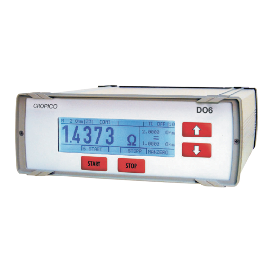
Page 10: Front Panel
DO6 Handbook 4. Controls 4.1 Front panel Front Panel with backlit LCD display and integral membrane keypad with tactile feedback 4.2 Button functions [START] In the measurement menu this button starts a measurement. In the configuration menu this button is assigned different functions depending on the text shown on the display above the button (soft key). - Page 11 DO6 Handbook 4.2 Rear panel 4.2.1 Description of connector sockets Measurement input Analogue GND Connector shell: PE (Protective ground) potential Mating connector: Burster type 9900-V172 Note: The current branch is protected by a fuse 6.3 x 32 mm 10AFF. (Rear side of...
- Page 12 DO6 Handbook Note: NEVER connect the cable shield to the connector shell if the grounding at the sensor end is unclear. Otherwise, if there is a ground connection at the temperature sensor, measuring errors may result from circulating ground-loop currents. (Connector shell is protective ground)
- Page 13 DO6 Handbook 5. Operating instructions in brief After switching on the instrument, the operating language can be selected in the identification menu. Pressing both arrow buttons simultaneously opens the configuration program. ENTER confirms the selected menu option. ESC can be used to return from any option in the configuration menu back to the next menu option down.
- Page 14 DO6 Handbook Present device program: XX Copy the selected device Device program Program copy program to the program from Initialize selected device program no. xx to no. yy Initialize complete device Comparator on, Relay on Comparator Comparator on, Relay off...
-
Page 15: Operation
DO6 Handbook 6. Operation 6.1 Meaning of the individual display segments Limits and the evaluation result are only displayed when the computer is enabled. When a measurement is in progress, the measurement counter increments from 0 to 9, changing whenever a new measurement result is available Danger warnings and error messages flash. -
Page 16: Startup Menu
DO6 Handbook 6.2 Start-up menu The first menu is displayed after power up: If LANGUAGE is not pressed within 3 seconds, the meter goes automatically into the measurement menu. NEXT switches to the measurement menu immediately. Note: If the ↑↓ buttons are a pressed simultaneously in this menu, within the 3 seconds, the service menu opens. -
Page 17: Configuration Menu
DO6 Handbook 6.3 Configuration menu If the ↑↓ buttons are pressed simultaneously, the instrument goes into the configuration state and displays menu 5. Menu 5 has three pages. Selection bar has inverse display. Press ↑↓ to move selection bar, ENTER to select and proceed to menu 10 –... -
Page 18: Measurement Menu
DO6 Handbook 6.4 Measurement menu Measurement mode Limits and the evaluation results are only displayed when the comparator is enabled. When a measurement is in progress, the measurement counter increments from 0 to 9, changing whenever a new measurement result is available. - Page 19 DO6 Handbook 6.5 Description of the individual setup menus 6.5.1 Measuring range Selection bar has inverse display. Press ↑↓ to move selection bar, ENTER to select, and ESC to return to menu 5 without making a change. The arrow in the right hand corner ↓ indicates that this is the first menu page.
- Page 20 DO6 Handbook Selection bar has inverse display. Press ↑↓ to move selection bar, ENTER to select, and ESC to return to menu 5 without making a change. The arrow in the right hand corner ↑ indicates that this is the last menu page.
- Page 21 DO6 Handbook 6.5.3 Load selection Selection bar has inverse display. Press ↑↓ to move selection bar, ENTER to select and return to menu 5, and ESC to return to menu 5 without making a change. Selection of LOAD / TIME CONSTANTS Z1, Z2, Z3 This is used to select the time constant Z of the current regulator: Z1 is set for purely resistive devices under test.
- Page 22 DO6 Handbook 6.5.3.1 Handling inductive loads e.g. reactors, cables on reels, motors, coils, transformers Safety instructions • The instrument has two measurement inputs connected in parallel; only one of these inputs must be used at any one time. No leads must be plugged into the unused connector for safety reasons.
- Page 23 DO6 Handbook The circuit diagram for the protection circuit is shown below: The diode provides a short-circuit for an inductive current and discharges an inductance down to a residual voltage of about 3 V. Even though particularly high-power diodes are used, sometimes there may be a problem at the end of the measurement (when disconnecting) if the device under test has a particularly high inductance.
-
Page 24: Measurement Mode
DO6 Handbook 6.5.4 Measurement mode Use ↑↓ to move the selection bar, ENTER to select. 6.5.4.1 Continuous operation Continuous operation means that the test current is switched on when the START button is pressed and not switched off until the STOP button is pressed. Mean values from n measurements are displayed. - Page 25 DO6 Handbook 6.5.4.2 Single shot Single shot means that although all measurements are displayed, only the n’th measurement reading is saved and compared with the limits (comparator). Then the current source is switched off. The first digitization takes about 400 ms (Z1, MAN ZERO, N=1), and subsequent digitizations about 100 ms each.
- Page 26 DO6 Handbook 6.5.4.3 Alternating measurement mode Alternating measurement mode means that the test current is switched on when the START button is pressed and not switched off until the STOP button is pressed. The current source is switched on and off continuously during the measurement to suppress any thermal EMF’s, so that the instrument remains permanently correctly “zeroed”.
- Page 27 DO6 Handbook 6.5.4.4 Cooling curve The cooling curve measurement mode is allowed in conjunction with all times constants, and manual and automatic zero offset. It is not allowed, however, in conjunction with comparator, automatic measuring range and automatic temperature compensation. The settling OHM/m is also ignored. Nor in this case is it possible to change the measuring range during the measurement time constant Z1.
- Page 28 DO6 Handbook Pressing CHANGE displays the following screen: The cursor sits over the first zero. Pressing ↑↓ increases or decreases the numerical value, while → moves the cursor one position to the right within the input field. After selecting the value, pressing ENTER saves the value and closes the menu.
- Page 29 Since the first resistance value cannot be measured until after a short delay after switching off the load current; the actual resistance at the time when the load was removed can only be found by extrapolating the cooling curve. The add-on PC software package DO6-P001 can be purchased to help perform this calculation.
-
Page 30: Temperature Compensation
DO6 Handbook 6.5.5 Temperature compensation Selection bar has inverse display. Press ↑↓ to move selection bar, ENTER to select, and ESC to return to the menu. Enabling temperature compensation changes the display value. The value displayed is the resistance that a device made of this material would have if its temperature were e.g. 20°C. - Page 31 DO6 Handbook 6.5.6 Autozero / Man-Zero Press ↑↓ to move selection bar, ENTER to select, and ESC to return to the menu. When Autozero is enabled, after pressing the START button, the voltage across the U terminals is detected and zeroed n times, initially with the current still off. The measurement is made using the selected measurement mode and the selected load.
-
Page 32: Device Program
DO6 Handbook 6.5.7 Device program Pressing the CHANGE button displays the following screen: Pressing ↑↓ increases or decreases the numerical value, while → moves the cursor to the right. Always enter a 2 digit number leading with zeros. ENTER loads the selected program. - Page 33 DO6 Handbook After pressing ENTER: Pressing ↑↓ increases or decreases the numerical value, while → moves the cursor to the right. Always enter a 2 digit number leading with zeros. The value for TO NO is entered in the same way.
- Page 34 DO6 Handbook 6.5.9 Contrast The following screen is displayed after pressing the CHANGE button: Pressing ↑↓ increases or decreases the numerical value, while → moves the cursor to the right. Always enter a 2 digit number leading with zeros. Jan 2006...
-
Page 35: Temperature Sensor
Permitted temperature range: 0°C to + 100°C * The A-B factors measured for the Pt100 sensor and the value for Ro (e.g. DKD certificate) can be transferred to the instrument using the PC software DO6-P001 (purchased separately). This enables accurate temperature measurement. - Page 36 DO6 Handbook The following screen is displayed if PYROMETER is selected: Pressing CHANGE displays the following screen: Pressing ↑↓ increases or decreases the numerical value, while → moves the cursor to the right. Always enter a 5 digit number leading with zeros.
- Page 37 DO6 Handbook The following screen is displayed if MANUAL is selected: Pressing CHANGE displays the following screen: Pressing ↑↓ increases or decreases the numerical value, while → moves the cursor to the right. Always enter a 5 digit number leading with zeros.
- Page 38 DO6 Handbook 6.5.12 Self test The instrument has numerous built-in diagnostics, which you can use to check whether the instrument is working correctly, and for self-help troubleshooting. Use ↑↓ to move the selection bar, ENTER to select Use ↑↓ to move the selection bar, ENTER to select The following screen appears after selecting “PLC &...
- Page 39 DO6 Handbook The following screen appears after selecting “SUPPLY VOLTAGE TEST”: If the screen doesn’t appear, one of the internal supply voltages are off; switch the device off and on again and try again. The following screen appears after selecting “SUPPLY VOLTAGE TEST”: The following screen appears after a waiting period of 10 s.
- Page 40 DO6 Handbook The following screen appears after selecting “AMPLIFIER TEST”: The following screen appears after selecting “CURRENT SOURCE TEST”: After selecting “DISPLAY TEST” all the characters on the display are run through from left to right. This test is terminated automatically after about 35 s.
-
Page 41: Data Output
DO6 Handbook 6.5.13 Data output Use ↑↓ to move the selection bar, ENTER to select Always print Setting PRINTER as data output means that every valid measurement is sent to the printer. Depending on the instrument setup a large amount of data can accrue, so please set the instrument and printer to the largest possible common transmission rate. - Page 42 DO6 Handbook 6.5.14 Access to password This is where one specifies whether the meter user can access all functions and settings of the instrument, or whether his access options are limited. On delivery, access is enabled for all settings. Pressing the ENTER button allows you to enter the password.
- Page 43 DO6 Handbook The following screen appears after selecting “CHANGE ACCESS” The current selection is highlighted. Press ↑↓ to move the selection bar, ENTER to select. The following screen appears after selecting “CHANGE PASSWORD” Use ↑↓ to increase or decrease the numerical value. Always enter a 4 digit number.
- Page 44 DO6 Handbook 6.5.15 Interface Use ↑↓ to move the selection bar, CHANGE to select. ↓ shows that there is a second page: For “BAUD RATE” and “DAT-FORMAT” use the ↑↓ buttons to toggle between the possible settings, and ENTER to adopt the setting shown.
-
Page 45: Reference Temperature
DO6 Handbook 6.5.16 Reference temperature Pressing the CHANGE button displays the following screen: Use ↑↓ to increase or decrease the numerical value. Always enter a 4 digit number. Important note: • If the reference temperature does not equal 20°C, CAL is displayed in the bottom status bar. - Page 46 DO6 Handbook 6.5.17 reference length Use ↑↓ to move the selection bar, ENTER to select. The default length is 1m. The following screen is displayed after pressing the CHANGE button. Use ↑↓ to increase or decrease the numerical value. Jan 2006...
- Page 47 The reference length is only taken into account and used for conversion in the instrument if “OHM PER METER” has been selected as the units. 6.5.18 Calibration The instrument is calibrated digitally. PC software type DO6-P001 and a range of series 1240 calibration resistances are required for this calibration. Jan 2006...
- Page 48 DO6 Handbook 7. Controlling the instrument remotely 7.1 Controlling the instrument via the PLC interface Jan 2006 48 of 107 pages...
- Page 49 DO6 Handbook 7.2 Controlling the instrument via the RS232 interface 7.2.1 Connector pin-out for the RS232 interface Jan 2006 49 of 107 pages...
-
Page 50: Interface Parameters
DO6 Handbook 7.2.2 Interface parameters The interface parameters can be set in menu 150 Interface. Baud rates: 300, 600, 1200, 2400, 4800, 9600(*), 19200, 38400, 56000, 57600 Data bits: 7 or 8(*) Stop bits: 1(*) or 2 Parity: none (*), even, odd... -
Page 51: Selection With Response
The control station sends a “selection supervisory sequence”. The selection supervisory sequence is used to initialize the DO6 as slave so that it is then possible to send it commands. The prefix calls up a single secondary station. <ENQ> defines the end of the selection supervisory sequence. - Page 52 7.2.7 Polling The control station sends a “polling supervisory sequence” The polling supervisory sequence is used to retrieve requested data from the DO6. The prefix selects a single station. <ENQ> defines the end of the “polling supervisory sequence”. The polling supervisory sequence of the DO6 has the following format: <group_address><user_address>po<ENQ>...
-
Page 53: Data Transfer
7.2.10.1 Communication using “selection with response” Controller sends: <EOT> To make sure that all possible existing connections are terminated and the DO6 receive memory is cleared. Controller sends: 0000sr<ENQ> Controller wishes to address the DO6 with the group address 0 and the user address 0. - Page 54 The host controller unaddresses the device in order to start a polling sequence immediately. Controller sends: 0000po<ENQ> The DO6 with group address 0 and user address 0 is required to send all responses waiting to be sent. DO6 sends response, with block check off: <STX>RESISTOMAT2316,3A,0123456789,V200401,09.12.2004,1<LF><ETX>...
- Page 55 7.3 General information 7.3.1 Interface watchdog timer 7.3.1.1 Timer A (response timer) Timer A is used by the DO6 to protect itself from an invalid response or no response at all. • Start: Timer A is started after data transfer has been terminated with <ETX>.
- Page 56 DO6 Handbook 8.2 SPCI registers Jan 2006 56 of 107 pages...
-
Page 57: Access Level
DO6 Handbook 8.3 ACCess Subsystem ACCess:LEVel DESCRIPTION: Sets the access levels. SYNTAX: ACCess:LEVel P1 Meaning of parameter Pn QUERY FORM: ACCess:LEVel ? RESPONSE: Meaning of response An NOTE: Command not allowed in calibration mode. Command not allowed when measurement is running. - Page 58 DO6 Handbook 8.4 DISPlay Subsystem ACCess:LEVel DESCRIPTION: Can be used to adjust the LCD contrast. SYNTAX: DISPlay:CONTrast P1 Meaning of parameter Pn QUERY FORM: DISPlay:CONTrast ? RESPONSE: Meaning of response An NOTE: Command not allowed in calibration mode. Command not allowed when measurement is running.
- Page 59 DO6 Handbook 8.5 CALCulate Subsystem 8.5.1 CALCulate:LIMit:STATe DESCRIPTION: Enables or disables the comparator function. SYNTAX: CALCulate:LIMit:STATe P1 Meaning of parameter Pn QUERY FORM: CALCulate:LIMit:STATe ? RESPONSE: Meaning of response An NOTE: Command not allowed in calibration mode. Command not allowed when measurement is running.
- Page 60 DO6 Handbook 8.5.2 CALCulate:LIMit:RELais DESCRIPTION: Enables or disables the relay function. SYNTAX: CALCulate:LIMit:RELais P1 Meaning of parameter Pn QUERY FORM: CALCulate:LIMit:RELais ? RESPONSE: Meaning of response An NOTE: Command not allowed in calibration mode. Command not allowed when measurement is running.
-
Page 61: Calculate:limit:lower
DO6 Handbook NOTE: Command not allowed in calibration mode. Command not allowed when measurement is running. 8.5.4 CALCulate:LIMit:RESet DESCRIPTION: Behaviour of comparator function. The comparator is reset with Start measurement (static behaviour) or not reset (dynamic behaviour). SYNTAX: CALCulate:LIMit:RESet P1... -
Page 62: Calculate:limit:upper
DO6 Handbook QUERY FORM: CALCulate:LIMit:LOWer? RESPONSE: Meaning of response An NOTE: Command not allowed in calibration mode. Command not allowed when measurement is running. 8.5.6 CALCulate:LIMit:UPPer DESCRIPTION: Sets the upper comparator limit. This value is not adopted, however, until the CALCulate:LIMit:ACKNowledge? command is received, once the upper comparator limit has also been transferred using the CALCulate:LIMit:LOWer command. - Page 63 DO6 Handbook 8.5.7 CALCulate:LIMit:ACKNowledge? DESCRIPTION: Adopts the comparator limits. This command causes those comparator limits to be adopted that were previously transferred using the two commands CALCulate:LIMit:LOWer (lower comparator limit) and CALCulate:LIMit:UPPer (upper comparator limit). SYNTAX: CALCulate:LIMit:ACKNowledge No parameter QUERY FORM:...
- Page 64 DO6 Handbook NOTE: Command not allowed in calibration mode. Command not allowed when measurement is running. 8.5.9 CALCulate:MATH[:EXPRession] DESCRIPTION: Switches the measurement display between Ohm and Ohm/m SYNTAX: CALCulate:MATH[:EXPRession] P1 Meaning of parameter Pn QUERY FORM: CALCulate:CONTrol:DATA ? RESPONSE: Meaning of response An NOTE: Command not allowed in calibration mode.
- Page 65 DO6 Handbook 8.6 REGister Subsystem 8.6.1 REGister:OUTPut DESCRIPTION: Tests the PLC outputs. The PLC outputs can be set/reset SYNTAX: REGister:OUTPut P1 Meaning of parameter Pn Bit-coding of the PLC outputs: → OUT_PROG_OK (Pin 4) → OUT_PROG_3 (Pin 17) → OUT_PROG_2 (Pin 16) →...
- Page 66 DO6 Handbook 8.6.2 REGister:INPut DESCRIPTION: Tests the PLC inputs. The PLC inputs can be read SYNTAX: REGister:INPut ? QUERY FORM: Query form only RESPONSE: Meaning of parameter An Bit-coding of the PLC inputs: → IN_RESERVE_4 → IN_RESERVE_3 (Pin 32) →...
- Page 67 DO6 Handbook 8.7 SCALE Subsystem 8.7.1 SCALE:VOLTage DESCRIPTION: Scales the voltage input from the pyrometer. SYNTAX: SCALE:VOLTage P1, P2, P3, P4 Meaning of parameter Pn Condition: Lower voltage < Upper voltage and lower temperature < Upper temperature QUERY FORM: SCALe:VOLTage?
- Page 68 DO6 Handbook 8.7.2 SCALE:PT100 DESCRIPTION: Sets the Pt100 coefficients for positive temperatures SYNTAX: SCALE:PT100 P1, P2, P3 Meaning of parameter Pn Equation: Rt = R0 * (1 + a * t + b * t²) QUERY FORM: SCALe:PT100? RESPONSE: A1, A2, A3...
- Page 69 DO6 Handbook 8.8 HCOPy Subsystem 8.8.1 HCOPy:DESTination DESCRIPTION: Sets the function of the serial port (Printer output of PC interface) SYNTAX: HCOPy:DESTination P1 Meaning of parameter Pn QUERY FORM: HCOPy:DESTination? RESPONSE: Meaning of parameter An NOTE: Command not allowed in calibration mode.
- Page 70 DO6 Handbook RESPONSE: Meaning of parameter An NOTE: Command not allowed in calibration mode. Command not allowed when measurement is running. 8.9.2 CCURve:TIME:DELTa DESCRIPTION: Sets the time interval between measurements (delta time) on the cooling. SYNTAX: CCURve:TIME:DELTa P1 Meaning of parameter Pn...
- Page 71 DO6 Handbook No parameter QUERY FORM: Query form only RESPONSE: Meaning of parameter An NOTE: Command not allowed in calibration mode. Command not allowed when measurement is running. 8.9.4 CCURve:DATA DESCRIPTION: Can be used to read the individual entries in the data logger.
- Page 72 DO6 Handbook 8.9.5 CCURve:CHARge DESCRIPTION: START / STOP time from load removal. SYNTAX: CCURve:CHARge P1 Meaning of parameter Pn QUERY FORM: No query form NOTE: Command not allowed in calibration mode. Command not allowed when measurement is running. Command only allowed in cooling curve mode.
- Page 73 DO6 Handbook 8.10 TRACe Subsystem 8.10.1 TRACe:DATA:LENGth DESCRIPTION: Transfers and queries the reference length. SYNTAX: TRACe:DATA:LENGth P1 Meaning of parameter Pn QUERY FORM: TRACe:DATA:LENGth? RESPONSE: Meaning of parameter An NOTE: Command not allowed in calibration mode. Command not allowed when measurement is running.
- Page 74 DO6 Handbook 8.11.2 INITiate[IMMediate] DESCRIPTION: Starts a measurement that has been stopped. SYNTAX: INITiate[IMMediate] No parameter QUERY FORM: No query form NOTE: Command not allowed in calibration mode. Command not allowed when measurement already started. For speed reasons there is also a non-SCPI-compliant short form: IN 8.11.3 TRACe:DATA:LENGth...
-
Page 75: System:version
DO6 Handbook 8.11.4 FETCh? DESCRIPTION: Can be used to retrieve one measurement. SYNTAX: FETCh? No parameter QUERY FORM: Query form only RESPONSE: A1, A2 Meaning of parameter An NOTE: Command not allowed in calibration mode. For speed reasons there is also a non-SCPI-compliant short form: FE 8.12 SYSTem Subsystem... -
Page 76: System Language
DO6 Handbook 8.12.2 SYSTem:LANGuage DESCRIPTION: Switches Sets and queries the operating language. SYNTAX: SYSTem:LANGuage P1 Meaning of parameter Pn QUERY FORM: SYSTem:LANGuage? RESPONSE: Meaning of parameter An NOTE: Command not allowed in calibration mode. Command not allowed when measurement is running. -
Page 77: System:error[:Next]
DO6 Handbook 8.12.4 SYSTem:ERRor[:NEXT]? DESCRIPTION: Can be used to query any errors that may have occurred in the instrument. SYNTAX: SYSTem:ERRor[:NEXT]? No parameter QUERY FORM: Query form only RESPONSE: Meaning of parameter An Jan 2006 77 of 107 pages... -
Page 78: Status:preset
DO6 Handbook 8.13 STATus Subsystem 8.13.1 STATus:PRESet DESCRIPTION: Resets both the Operational Status Enable register and the Questionable Status Enable register to 0. SYNTAX: STATus:PRESet No parameter QUERY FORM: No query form 8.13.2 STATus:OPERation:ENABle DESCRIPTION: Sets the Operational Status Enable register. - Page 79 DO6 Handbook 8.13.3 STATus:QUEStionable:ENABle DESCRIPTION: Sets the Questionable Status Enable register. SYNTAX: STATus:QUEStionable:ENABle P1 Meaning of parameter Pn QUERY FORM: STATus:QUEStionable:ENABle? RESPONSE: Meaning of parameter An 8.13.4 STATus:OPERation:CONDition? DESCRIPTION: Reads the Operation Status Condition register. SYNTAX: STATus:OPERation:CONDition No parameter QUERY FORM:...
- Page 80 DO6 Handbook 8.13.5 STATus:QUEStionable:CONDition? DESCRIPTION: Reads the Questionable Status Condition register. SYNTAX: STATus:QUEStionable:CONDition? No parameter QUERY FORM: Query form only RESPONSE: Meaning of parameter An Note: For speed reasons there is also a non-SCPI-compliant short form: S:Q:C? 8.13.6 STATus:OPERation[:EVENt]? DESCRIPTION: Reads the Operation Status Event register.
- Page 81 DO6 Handbook 8.13.7 STATus:QUEStionable[:EVENt]? DESCRIPTION: Reads the Questionable Status Event register. SYNTAX: STATus:QUEStionable:[EVENt]? No parameter QUERY FORM: Query form only RESPONSE: Meaning of parameter An Note: For speed reasons there is also a non-SCPI-compliant short form: S:Q:[E[? Jan 2006 81 of 107 pages...
- Page 82 DO6 Handbook 8.14 SENSe Subsystem 8.14.1 SENSe:TCOMpensate DESCRIPTION: Sets the type of temperature sensor for the temperature compensation detected. SYNTAX: SENSe:TCOMpensate P1 Meaning of parameter Pn QUERY FORM: SENSe:TCOMpensate? RESPONSE: A1, A2, A3, A4 Meaning of parameter An NOTE: Command not allowed in calibration mode.
- Page 83 DO6 Handbook Meaning of parameter An NOTE: Command not allowed in calibration mode. Command not allowed when measurement is running. 8.14.3 SENSe:TCOMpensate:TEMperature DESCRIPTION: Sets the temperature for manual temperature compensation. SYNTAX: SENSe:TCOMpensate:TEMperature P1 Meaning of parameter Pn QUERY FORM: SENSe:TCOMpensate:TEMperature?
- Page 84 DO6 Handbook 8.14.4 SENSe:TCOMpensate:TEMperature:REFerence DESCRIPTION: Sets the reference temperature for temperature compensation. SYNTAX: SENSe:TCOMpensate:TEMperature:REFerence P1 Meaning of parameter Pn QUERY FORM: SENSe:TCOMpensate:TEMperature? RESPONSE: Meaning of parameter An NOTE: Command not allowed in calibration mode. Command not allowed when measurement is running.
- Page 85 DO6 Handbook 8.14.5 SENSe:TCOMpensate:TCOefficient:SELect DESCRIPTION: Selects a temperature coefficient for the temperature compensation. SYNTAX: SENSe:TCOMpensate:TCOefficient:SELect P1 Meaning of parameter Pn QUERY FORM: SENSe:TCOMpensate:TCOefficient:SELect? RESPONSE: Meaning of parameter An NOTE: Command not allowed in calibration mode. Command not allowed when measurement is running.
- Page 86 DO6 Handbook 8.14.6 SENSe:TCOMpensate:TCOefficient:USER:CHANge DESCRIPTION: Can be used to set the user-defined temperature coefficients. SYNTAX: SENSe:TCOMpensate:TCOefficient:USER:CHANge P1, P2, P3 Meaning of parameter Pn QUERY FORM: SENSe:TCOMpensate:TCOefficient:USER:CHANge? RESPONSE: A1, A2, A3 Meaning of parameter Pn Meaning of response An NOTE: Command not allowed in calibration mode.
- Page 87 DO6 Handbook 8.14.7 SENSe:FRESistance:RESolution DESCRIPTION: Sets the resolution of the measurement display. SYNTAX: SENSe:FRESistance:RESolution P1 Meaning of parameter Pn QUERY FORM: SENSe:FRESistance:RESolution? RESPONSE: Meaning of parameter An NOTE: Command not allowed in calibration mode. Command not allowed when measurement is running.
- Page 88 DO6 Handbook Meaning of parameter An NOTE: Command not allowed in calibration mode. Command not allowed when measurement is running. RESistance can also be used instead of FRESistance. 8.14.9 SENSe:FRESistance:TIME:CONStant DESCRIPTION: Sets the load type of the device under test.
- Page 89 DO6 Handbook 8.14.10 SENSe:FRESistance:RANGe DESCRIPTION: Can be used to query the measuring range currently in use. SYNTAX: SENSe:FRESistance:RANGe P1 No parameters QUERY FORM: SENSe:FRESistance:RANGe? RESPONSE: Meaning of Response An NOTE: Command not allowed in calibration mode. RESistance can also be used instead of FRESistance.
- Page 90 DO6 Handbook NOTE: Command not allowed in calibration mode. Command not allowed when measurement is running. RESistance can also be used instead of FRESistance. 8.14.12 SENSe:FRESistance:RANGe:UPPer DESCRIPTION: Sets the maximum permitted measuring range for automatic range selection. SYNTAX: SENSe:FRESistance:RANGe:UPPer P1...
- Page 91 DO6 Handbook 8.14.13 SENSe:FRESistance:RANGe:LOWer DESCRIPTION: Sets the minimum permitted measuring range for automatic range selection. SYNTAX: SENSe:FRESistance:RANGe:LOWer P1 Meaning of parameter Pn QUERY FORM: SENSe:FRESistance:RANGe:LOWer? RESPONSE: Meaning of parameter An NOTE: Command not allowed in calibration mode. Command not allowed when measurement is running.
- Page 92 DO6 Handbook 8.14.14 SENSe:FRESistance:RANGe:MANual DESCRIPTION: Sets the measuring range for manual range selection. SYNTAX: SENSe:FRESistance:RANGe:MANual P1 Meaning of parameter Pn QUERY FORM: SENSe:FRESistance:RANGe:MANual? RESPONSE: Meaning of parameter An NOTE: Command not allowed in calibration mode. Command not allowed when measurement is running and an inductive device under test is set.
- Page 93 DO6 Handbook 8.14.15 SENSe:AVERage:COUNt DESCRIPTION: Sets the number of measurements to be used for calculating the mean resistance. SYNTAX: SENSe:AVERage:COUNt P1 Meaning of parameter Pn QUERY FORM: SENSe:AVERage:COUNt? RESPONSE: Meaning of parameter An NOTE: Command not allowed in calibration mode.
- Page 94 DO6 Handbook 8.14.17 SENSe:CORRection:OFFset:STATe DESCRIPTION: Enables/disables the automatic thermal-EMF compensation. SYNTAX: SENSe:CORRection:OFFset:STATe P1 Meaning of parameter Pn QUERY FORM: SENSe:CORRection:OFFset:STATe? RESPONSE: Meaning of parameter An NOTE: Command not allowed in calibration mode. Command not allowed when measurement is running. 8.15 IEEE-488.2 commands 8.15.1 *SRE command...
- Page 95 DO6 Handbook 8.15.2 *STB? command DESCRIPTION: Reads the Status Byte register. SYNTAX: STB? No parameter QUERY FORM: Query form only RESPONSE: Meaning of parameter An 8.15.3 *ESE command DESCRIPTION: Sets the Standard Event Status Enable register. SYNTAX: *ESE P1 Meaning of parameter Pn...
- Page 96 DESCRIPTION: Sets the device to the Operation Complete Active state (OCAS). SYNTAX: NOTE: This command has no function on the DO6 No point to it on the serial port with ANSI protocol. 8.15.6 *RST command DESCRIPTION: Sets the device to a defined initial state.
- Page 97 RESPONSE: Meaning of response An 8.15.8 *WAI command DESCRIPTION: This command configures the device to handle all commands sequentially. This command has no function on the DO6 because commands are always handled sequentially. The command is merely recognised. SYNTAX: *WAI...
- Page 98 DO6 Handbook 8.15.10 *IDN? command DESCRIPTION: Retrieves various information for device identification. SYNTAX: *IDN? No parameter QUERY FORM: Query form only RESPONSE: A1, A2, A3, A4, A5, A6 Meaning of response An 8.15.11 *IDN? command DESCRIPTION: Can be used to select a measurement program (0 to 15).
- Page 99 DO6 Handbook 8.16 Programming examples QBasic examples These two examples were written using Quick-Basic, and in both methods shown retrieve the info string 8.16.1 Communication using “Selection with response” Jan 2006 99 of 107 pages...
- Page 100 DO6 Handbook Jan 2006 100 of 107 pages...
- Page 101 DO6 Handbook 8.16.2 Communication using “Fast selection” Jan 2006 101 of 107 pages...
- Page 102 DO6 Handbook Jan 2006 102 of 107 pages...
-
Page 103: Maintenance
DO6 Handbook 9. Maintenance, Customer service, Shipping, Cleaning Maintenance The DO6 requires no maintenance by the user. Any repairs that may be needed must be performed only at the manufacturer’s premises. Recalibration is recommended every 24 months. Customer Service Queries:... -
Page 104: Technical Data
DO6 Handbook 10. Appendix 10.1 Technical data Only values that include tolerances or limits are data covered by the warranty. Values that do not include tolerances are provided for information and do not come under the warranty. The instrument is designed for easy servicing and is housed in a rugged metal case. The individual components are easily accessible, ensuring ideal servicing conditions. - Page 105 DO6 Handbook Inductive loads: Three different regulator parameters preset to give optimum speed, protection circuit, discharge of inductance. Measurement fault: Oscillation detection Open circuit detection Pt100 absence detection Warm up time: < 15 mins until error tolerances are reached Auxiliary power: 100 …...
-
Page 106: Error Messages And Troubleshooting
DO6 Handbook 10.2 Calibration The instrument is calibrated digitally. PC software (to be purchased separately) and a range of calibration resistances are required for the calibration. 10.3 Error messages and troubleshooting Fault Possible cause Remedial action Display does not Mains fuse blown. - Page 107 DO6 Handbook Internal device errors After power up, the instrument checks the calibration data in the data memory, the non-volatile variables in the data memory and the EEPROM on the analogue card. Since more than one error can occur at once, the errors are binary coded and displayed on the LCD in the event of an error.
Need help?
Do you have a question about the DO6 and is the answer not in the manual?
Questions and answers