Advertisement
Quick Links
Advertisement

Related Manuals for Major tech MT250

Summary of Contents for Major tech MT250
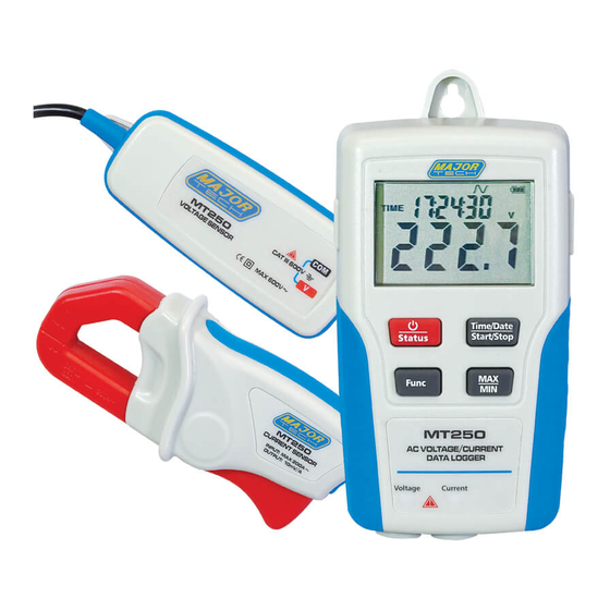
- Page 1 INSTRUCTION MANUAL MT250 AC VOLTAGE/CURRENT DATA LOGGER...
-
Page 3: Table Of Contents
Contents Page no 1. Introduction..................5 2. Features...................5 3. Function Description................6 4. Data Memory and Data Transmitting............8 5. Caution Before Connecting..............8 6. Software Introduction................8 6.1. Installation................6 6.2. Operation.................9... - Page 4 Warning! Ÿ Do not attempt to make measurement in flammable gaseous areas! Ÿ When testing non-insulated cable, pay attention to avoiding short circuiting the cable. Ÿ Do not attempt to use the instrument when your hand is wet! Ÿ Do not apply over voltage and currents during measurement. Ÿ...
-
Page 5: Introduction
1. INTRODUCTION This Data Logger is designed and produced according to IEC61010 safety standard, tested and inspected to factory specifications. This data logger is a precision instrument for recording AC current and AC voltage. It is more convenient to use with the LCD display and buttons. -
Page 6: Function Description
3. FUNCTION DESCRIPTION 1. LCD Display Function Range Date and time Recording indication The waveform of the measuring current and voltage (This unit can only measure a wave whose waveform resembles a sine curve) Battery sign, when displaying completely, it means battery power is full. - Page 7 2. Power supply socket DC voltage supply (6V-9V) 3. USB socket When transmitting data with PC software, stop recording before connecting to PC with the USB cable. 4. ON/OFF & data logger status button Press the button to power on. Hold the button to power off. Press the button to check which channel data is being recorded.
-
Page 8: Data Memory And Data Transmitting
4. Data memory and Data transmitting Ÿ If you want to start recording, the corresponding sensor must connect to the data logger or you can not start it. In the process of measurement if the sensor is disconnected because of some reason it will stop recording. -
Page 9: Operation
6.2. Operation Time setting: The time will be set when it is connected to your PC. If you find the DATA LOGGER time is incorrect, click the “ ” icon to open the below dialog. Input the correct date and correct time and select the date format display on the Data Logger , and click “OK”... - Page 10 Data download: Click the Download icon “ ” to download the data in the Data Logger. Yellow line is for current data and green line is for voltage data P.S: Please refer to the software manual for other software operation.
- Page 12 MAJOR TECH (PTY) LTD South Africa Australia www.major-tech.com www.majortech.com.au sales@major-tech.com info@majortech.com.au...
Need help?
Do you have a question about the MT250 and is the answer not in the manual?
Questions and answers