Advertisement
Quick Links
Advertisement

Related Manuals for Aquaguard BS925 2021

Summary of Contents for Aquaguard BS925 2021
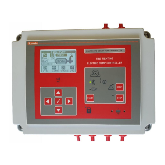
- Page 1 AquaGuard BS9251:2021 Fire Pump Controller User & Installation Manual Page | 1...
-
Page 2: Table Of Contents
5. Commissioning Page 9 6. Annual Maintenance Page 10 7. Fault Alarm Table Page 11 8. Troubleshooting Page 12 - 13 If additional assistance or information is required, please contact AquaGuard Pumps Technical on 0800 040 7738. Page | 2... -
Page 3: Product Description
1. Product Description The AquaGuard fire pump controller has been designed as an easy to install, all in one solution to control the operation, monitoring and automatic testing of the fire pump in accordance with BS9251:2021. Incorporating an informative LCD display, easy to use interface and a 128 event log making the AquaGuard fire pump controller the most advanced on the market. -
Page 4: User Interface
2. User Interface 2.1 – AquaGuard fire pump controller button and LED description. 2.2 – AquaGuard fire pump controller LCD Display ‘Home Screen’ description. Controller Home Screen Page | 4... -
Page 5: Installation Guide
RCD/RCBO suitably sized for the fire pump installed. Installation 3.4 – If purchasing in kit form the AquaGuard Fire Pump Controller must be connected as per diagram below. Take care with solenoid connection as 230v will be present to solenoid when requested. -
Page 6: Controller Set Up And User Guide
4. Controller Set Up and User Guide 4.1 – Once controller has been wired as per diagram (Fig.1) the controller power supply can be switched on, please note that on initial power up the pump will run to reach system pressure, please ensure that all suction valves are open and pump has been fully primed and free of any air before switching on for the first time. - Page 7 Note: Access to the setup menu is possible by entering an advanced password but the installer will be required to speak to Aquaguard technical to obtain and discuss required changes, as any changes in this menu without technical guidance could affect operation and invalidate warranty.
- Page 8 4.5 – Jockey Limit Reset If the pump has entered jockey mode five times or more within a week then the ‘Jockey Limit’ fault will be displayed, this may also be displayed shortly after start-up/initial filling of the system. To reset the ‘Jockey Limit’ initiate a weekly test procedure by following the steps in 5.3.
-
Page 9: Commissioning
0.3 bar of each other. Refer to pressure switch instruction manual for setting instructions, this should be undertaken with the Aquaguard pump controller switched off. 5.2 – Flow Test... -
Page 10: Annual Maintenance
6.2 – Event Log The Aquaguard controller has a 128 entry event log incorporated, this indicates in detail with a date and time every event that has occurred. To view, from the controller home screen press the up key until the ‘Event Log’ screen is displayed, then use the left and right keys to navigate through the log. -
Page 11: Fault Alarm Table
8. Fault Alarm Table If any faults are present on the controller then these will be displayed on the LCD display with a code A01 – A38 or UA1 - 8, see alarm table below for description. Page | 11... -
Page 12: Troubleshooting
Jockey Limit Fault Displayed Pressure switch has been Reset via procedure in section activated more than five times 4.5. in a week. If the controller is suspected to be faulty call Aquaguard on 0800 040 7738 for advice. Page | 12... - Page 13 Pump running for more than 62 Normal under fire pump seconds. condition if pump running for more than 1 minute. Faulty component – Investigate. If the controller is suspected to be faulty call Aquaguard on 0800 040 7738 for advice. Page | 13...
Need help?
Do you have a question about the BS925 2021 and is the answer not in the manual?
Questions and answers