Table of Contents
Advertisement
Advertisement
Table of Contents

Related Manuals for Aquaguard BS9251

Summary of Contents for Aquaguard BS9251
- Page 1 AquaGuard BS9251 Fire Pump Controller User & Installation Manual Page | 1...
-
Page 2: Table Of Contents
Page 8 6. Annual Maintenance Page 9 7. NFC Connectivity Page 10 8. Fault Alarm Table Page 11 9. Troubleshooting Page 12 If additional assistance or information is required, please contact AquaGuard Pumps Technical on 0800 040 7738. Page | 2... -
Page 3: Product Description
1. Product Description The AquaGuard fire pump controller has been designed as an easy to install, all in one solution to control the operation, monitoring and automatic testing of the fire pump in accordance with BS9251:2014. Incorporating an informative LCD display and optional Mobile App to assist programming and view/save event logs making the AquaGuard fire pump controller the most advanced on the market. -
Page 4: User Interface
2. User Interface 2.1 – AquaGuard fire pump controller button and LED description. 2.2 – AquaGuard fire pump controller LCD Display ‘Home Screen’ description. Controller Home Screen Page | 4... -
Page 5: Installation Guide
Installation 3.4 – AquaGuard Fire Pump Controller must be connected as per diagram below. The current check only version will not have the solenoid cable present. Take care with solenoid connection as 230v will be present to solenoid when requested. -
Page 6: Controller Set Up
4. Controller Set Up 4.1 – Once controller has been wired as per diagram (Fig.1) the controller power supply can be switched on, please note that on initial power up the pump will run to reach system pressure, please ensure that all suction valves are open and pump has been fully primed and free of any air before switching on for the first time. - Page 7 Warning: All controllers are pre-programed and tested to comply with BS9251, only change the current and power parameters to suit installed pump, changes to any other parameters may prevent the controller from operating correctly and will invalidate the warranty.
-
Page 8: Commissioning
‘most unfavourable hydraulic calculations’. Refer to pressure switch instruction manual for setting instructions, this should be undertaken with the Aquaguard pump controller switched off. 5.2 – Flow Test From the pump test valve a flow test should be undertaken to check pump satisfies the flow and pressure requirements set out in the system Hydraulic Calculations, after 15 seconds of the system flowing the ‘Sprinkler Activated’... -
Page 9: Annual Maintenance
6.2 – Event Log The Aquaguard controller has a 128 entry event log incorporated, this indicates in detail with a date and time every event that has occurred. To view, from the controller home screen press the up key until the ‘Event Log’... -
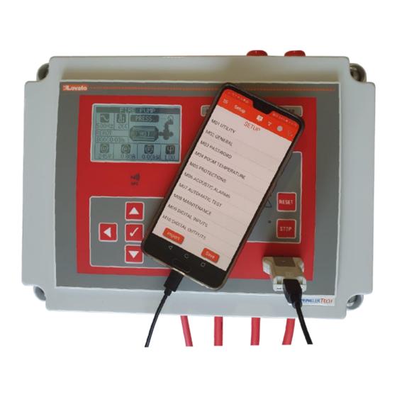
Page 10: Nfc Connectivity
2. Once downloaded, open the app and select ‘Download Driver’, once complete will display ‘Driver downloaded successfully’. 3. Hold the mobile device to the NFC symbol on the Aquaguard controller, may have to move phone around slightly to achieve a connection. The NFC works when the controller is off, if the controller is powered on then the ‘Manual mode’... -
Page 11: Fault Alarm Table
8. Fault Alarm Table If any faults are present on the controller then these will be displayed on the LCD display with a code A01 – A38, see alarm table below for description. Page | 11... -
Page 12: Troubleshooting
Refer to fault alarm table in Undertaken action if possible. controller section 8 to identify fault and possible action required. Call Aquaguard if problem persists. Page | 12 If the controller is suspected to be faulty call Aquaguard on 0800 040 7738 for advice.
Need help?
Do you have a question about the BS9251 and is the answer not in the manual?
Questions and answers