
Related Manuals for RHOSS H51369


Summary of Contents for RHOSS H51369
- Page 1 MACROSYSTEM ISTRUZIONI PER L’USO INSTRUCTIONS FOR USE Torri di raffreddamento CEHV 46÷639 Cooling towers H51369 Italiano English...
- Page 2 E’ vietata la riproduzione la memorizzazione e la trasmissione anche parziale della presente pubblicazione, in qualsiasi forma, senza la preventiva autorizzazione scritta della RHOSS RHOSS S.p.A. I centri di assistenza tecnica della S.p.A. sono disponibili a risolvere qualunque dubbio inerente all’utilizzo dei suoi prodotti ove la manualistica fornita risulti non soddisfacente.
- Page 3 1. PREMESSA Questo manuale vuole essere una guida generale per l’installazione, l'uso e la manutenzione delle torri di raffreddamento (o “torri evaporative”) serie " CEHV" per acque industriali. Prima di effettuare qualsiasi intervento o attività, leggere attentamente le istruzioni contenute nel presente manuale;...
-
Page 4: Descrizione Della Macchina
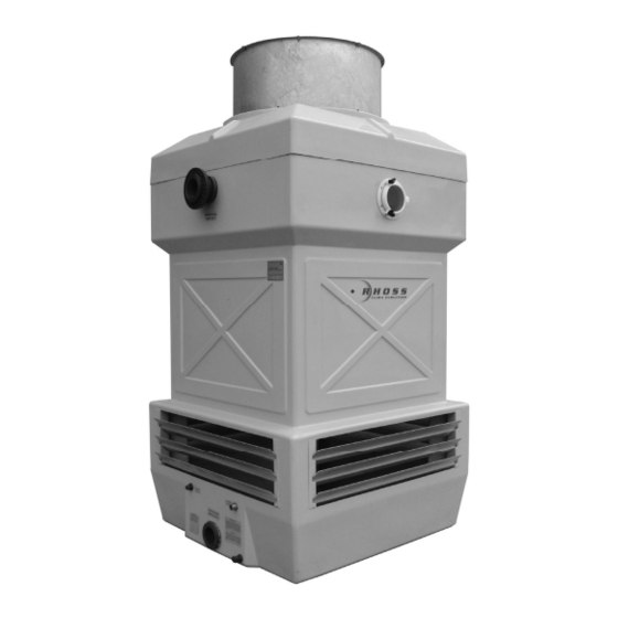
2. DESCRIZIONE DELLA MACCHINA [Fig. 02]... - Page 5 FAN GUARD RETE DI SCHERMO VENTILATORE ELECTRIC MOTOR MOTORE ELETTRICO ANELLO DI SOSTEGNO VENTILATORE FAN MOTOR SUPPORT GIRANTE CON PALE IN MATERIALE PLASTICO FAN BLADES MADE IN PLASTIC MATERIAL CORPO IN VETRORESINA BODY IN FIBERGLASS LOUVERS GRIGLIE DI INGRESSO ARIA OVER-FLOW TROPPO PIENO MAKE-UP BY FLOATING VALVE...
-
Page 6: Avvertenza Importante
3. TRASPORTO E STOCCAGGIO, POSIZIONAMENTO ED INSTALLAZIONE DELLA MACCHINA 3.1 Trasporto e stoccaggio Tutte le torri sono facilmente trasportabili secondo un concetto di pre-montaggio in 2 parti. Le dimensioni dei vari elementi sono in sagoma e, pertanto, è possibile il trasporto su normali autocarri. Il corpo della torre deve sempre viaggiare in posizione verticale ed il cappello in posizione orizzontale, come sotto raffigurato. - Page 7 3.2 Movimentazione della macchina AVVERTENZA ! Tutte le fasi di movimentazione e sollevamento devono essere eseguite da personale specializzato, utilizzando mezzi aventi portata idonea La movimentazione delle torri (carico, scarico e posizionamento definitivo) deve sempre essere effettuata con la massima attenzione e con l’utilizzo di mezzi idonei quali: - Carrelli elevatori - Autogrù...
- Page 8 3.3. Posizionamento 3.3.1 Parametri e considerazioni generali Il buon funzionamento della torre evaporativa dipende anche dall’osservanza di alcune regole di carattere generale ma di fondamentale importanza, alle quali è bene attenersi in fase di posizionamento ed installazione della macchina. In breve, tali regole sono le seguenti: - la torre di raffreddamento deve sempre essere installata all’esterno, possibilmente in posizione ben aerata ed osservando una minima distanza (almeno l’equivalente dell’ampiezza di una bocca di aspirazione aria) da pareti e fabbricati.
- Page 9 3.4 Installazione 3.4.1 Note generali La torre deve sempre essere installata su una superficie piana, perfettamente orizzontale e, se in versione con vasca, in modo che l’appoggio sotto di essa sia uniforme e continuo. 3.4.2 Assemblaggio dei componenti 3.4.2.1 Versione con vasca Nel caso di una versione con vasca, per motivi dovuti al trasporto la torre di raffreddamento verrà...
- Page 10 3.4.3 Allacciamento elettrico Tutte le torri evaporative della serie CEHV sono dotate di motori elettrici normalmente già predisposti per l’allacciamento ad una linea trifase [Fig. 09]. IMPORTANTE ! Tutti i collegamenti elettrici devono essere eseguiti da personale specializzato, predisponendo anche la messa a terra del motore. Provvedere all’installazione di un sezionatore a chiave nelle immediate vicinanze del motoventilatore.
- Page 11 3.4.4 Allacciamento idraulico Nella parte superiore del corpo si trovano, a seconda dei modelli, una o più connessioni che fanno capo al collettore di distribuzione dell’acqua interno alla torre ed alle quali va collegata la tubazione di arrivo dell’acqua dall’impianto. Per tutti i modelli CEHV, l’attacco di ingresso acqua è...
- Page 12 Il gruppo manometro con rubinetto di spurgo deve essere installato in prossimità della flangia di ingresso dell’acqua calda [Fig. 12] in torre ed ha la duplice funzione di verificare la pressione dell’acqua in arrivo alla torre e di consentire un agevole prelievo di acqua dal circuito per i periodici controlli circa la sua qualità chimico fisica.
-
Page 13: Avviso Di Sicurezza
3.4.5 Trattamento dell’acqua di reintegro Il raffreddamento avviene per evaporazione di una certa quantità dell’acqua in circolo, secondo una ben precisa legge fisica ed in volume che dipende dalla quantità di calore da smaltire. L’acqua che evapora ha bassissimo contenuto di sali, che aumentano invece la loro concentrazione nel circuito di raffreddamento sino a giungere a saturazione ed a depositarsi sia all’interno delle tubazioni che sulla superficie del pacco di scambio, compromettendo il buon funzionamento dell’intero impianto. -
Page 14: Messa In Funzione
4. MESSA IN FUNZIONE 4.1 Controlli preliminari Prima di effettuare la messa in funzione dell’impianto di raffreddamento, preventivamente riempito di acqua, effettuare le seguenti operazioni e verifiche: 1) far girare il ventilatore e controllare che questo giri in senso tale per cui l'aria entri dalle bocche inferiori ed esca dall'apertura cilindrica superiore. - Page 15 5. ESERCIZIO 5.1 Condizioni operative Le normali condizioni di utilizzo delle torri di raffreddamento serie CEHV sono le seguenti: - pressione massima dell’acqua di alimentazione 0,5 bar (5 metri col. H2O) - temperatura massima acqua in ingresso 55 °C (versioni standard) 75 °C (versione ATT) 5.2 Reintegro con acqua di fiume Quando si usi per il reintegro delle torri di raffreddamento acqua di fiume, oltre ai problemi di acidità...
-
Page 16: Avvertenze Di Sicurezza
5.4.2 Formazione di ghiaccio nei tubi del circuito L'acqua nei tubi ghiaccia a cominciare dagli strati a contatto della parete del tubo ed il fenomeno rallenta man mano che il gelo procede verso il centro. L’acqua, trasformandosi in ghiaccio all’interno dei tubi, aumenta di volume di circa l’8%, provocando quasi sempre la rottura dei tubi medesimi. -
Page 17: Manutenzione
7. MANUTENZIONE AVVERTENZA ! Tutte le operazioni di manutenzione devono essere eseguite da personale specializzato o direttamente dalla casa costruttrice, impiegando sempre procedure di lavoro in sicurezza 7.1 Manutenzione dell'involucro L’involucro nel suo complesso non necessita di alcun intervento di manutenzione. Eventuali operazioni di pulizia possono essere effettuate mediante semplice lavaggio con acqua e sapone o detersivi. - Page 18 7.6 Manutenzione delle alette paraspruzzi (solo versione con vasca) Le alette paraspruzzi, poste sulle bocche di ingresso aria, sono realizzate in poltruso di vetroresina e non necessitano di alcuna manutenzione particolare. Curare unicamente che i passaggi tra le alette siano sempre liberi e non ostruiti da corpi estranei (es.: fogli di giornale) in modo che l'aria, aspirata dal ventilatore, entri senza ostacoli nella torre.
-
Page 19: Ricerca Guasti
8. RICERCA GUASTI Problema - inconveniente Cause Soluzione Controllare la direzione del flusso dell'aria di Sezionare l'alimentazione del motoventilatore attraversamento della torre ed invertire due fasi delle tre fasi nella linea di Assorbimento elettrico eccessivo del alimentazione motoventilatore Controllare la temperatura dell'aria ambientale, Contattare l'ufficio tecnico infatti potrebbe succedere che in presenza di temperature ambientali basse il motore renda più... - Page 20 9. ACCESSORI Per ciascun modello di torre evaporativa sono disponibili diversi accessori e varianti costruttive che possono essere forniti con la torre stessa e, per alcuni di essi, anche in un secondo tempo. RESISTENZA ELETTRICA Serve ad evitare la formazione di ghiaccio nella vasca durante eventuali fermate dell’impianto nella stagione fredda.
- Page 21 ITALIANO Page 3 ENGLISH Page 22 INDEX Introduction Page 22 Description of the equipment Page 23 Transport, layout and installation of the equipment Page 25 Start-up/Commissioning Page 33 Operation Page 34 Safety warnings Page 35 Maintenance Page 36 Trouble-shooting guide Page 38 Accessories Page 39...
- Page 22 1. INTRODUCTION This manual is intended to be a general guide to the installation, the use and the maintenance of the "CEHV" series of evaporative cooling towers for industrial water cooling applications. Prior to performing whatever intervention or activity for the unit, the instructions contained in this manual should be carefully read;...
-
Page 23: Description Of The Equipment
2. DESCRIPTION OF THE EQUIPMENT [Fig. 02]... - Page 24 FAN GUARD RETE DI SCHERMO VENTILATORE ELECTRIC MOTOR MOTORE ELETTRICO ANELLO DI SOSTEGNO VENTILATORE FAN MOTOR SUPPORT GIRANTE CON PALE IN MATERIALE PLASTICO FAN BLADES MADE IN PLASTIC MATERIAL CORPO IN VETRORESINA BODY IN FIBERGLASS LOUVERS GRIGLIE DI INGRESSO ARIA OVER-FLOW TROPPO PIENO MAKE-UP BY FLOATING VALVE...
- Page 25 3. TRANSPORT, LAYOUT AND INSTALLATION OF THE UNIT 3.1 Trasport All towers are easily transportable, following a pre-mounting concept in two sections. The dimensions of the various segments are within normal vehicle limits and consequently their transport can be effected on standard lorries. The tower casing must always travel in a vertical position and, in the same way and the top part in a horizontal position as shown below [Fig.
- Page 26 3.2 Moving the Unit CAUTION ! All the phases of moving, positioning and lifting must be performed by specialized personnel, using devices of appropriate capacity Moving the towers (loading, unloading and final positioning) must always be performed with maximum care and using appropriate devices such as: - Fork-lift trucks - Mobile cranes...
- Page 27 3.3. Layout 3.3.1 Parameters and general considerations Correct operation of the evaporative cooling tower is also dependent upon the observance of several rules of a general nature but of fundamental importance, to which it is advisable to adhere already in the phase of choice of the place for installation of the equipment.
-
Page 28: Installation
3.4 Installation 3.4.1 General notes The cooling tower must always be installed on a flat, perfectly horizontal surface and, if in the version with basin, in such a way that the underlying support is both uniform and uninterrupted. 3.4.2 Assembly of the components 3.4.2.1 Version with basin n the case of a version with basin, for transportation reasons the cooling tower will be delivered in two pieces: the main casing and the top part. - Page 29 3.4.3 Electric Wiring All the CEHV series cooling towers are equipped with electric motors usually ready for connection to a 3-phase electrical supply [Fig. 09]. IMPORTANT ! All electric wiring must be performed by specialist personnel, also allowing for the earthing of the motor. Provide for the installation of a circuit-breaker with key nearby the motor-fan set.
- Page 30 3.4.4 Hydraulic connections One or more connections, depending upon the model, are located on the upper part of the main casing : these are at the entry to the water distribution header inside the tower and to these must be connected the piping of the hot water supply from the installation to be cooled.
- Page 31 The manometer set with bleed-off tap must be installed close to the hot water inlet flange (see figure below) into the tower and has the dual purpose of measuring the incoming pressure of the water into the tower and of allowing ready sampling of water from the circuit for the periodic checks on its chemical and physical qualities.
-
Page 32: Safety Warning
3.4.5 Trattamento dell’acqua di reintegro The cooling is obtained from the evaporation of a certain quantity of the circulating water, in accordance with a precise law of physics, and in a volume dependent upon the quantity of heat to be rejected. The water which evaporates has no salt content, whereas in the cooling circuit the salts present increase in concentration until they reach saturation point and start to deposit out of solution both on the inside of the piping and on the fill pack/heat exchange surface, compromising the correct operation of the whole plant. - Page 33 4. START-UP 4.1 Preliminary checks Prior to starting-up the cooling plant, previously filled with water, perform the following operations and checks: 1) Operate the fan and check that it rotates in the direction such that the air enters via the lower openings and leaves through the top cylindrical opening.
-
Page 34: Operation
5. OPERATION 5.1 Operating conditions The normal conditions of usage of the CEHV series cooling towers are as follows: - maximum water supply pressure 0,5 bar (5 meters W.G.) - maximum water inlet temperature 55 °C (standard versions) 75 °C (ATT version) 5.2 Make-up with river water When river water is employed for cooling tower make-up, apart from the problems of acidity and hardness normally associated with make-up water of any origin, one must evaluate with great care the possible presence... -
Page 35: Safety Warnings
5.4.2 Ice formation in the circuit piping The water in the piping forms ice starting from the layers in contact with the tube wall and the phenomenon slows progressively as the freezing proceeds towards the centre. The water, transforming itself into ice inside the pipes, increases in volume by about 8%, nearly always causing the splitting open of the latter. -
Page 36: Maintenance
7. MAINTENANCE WARNING ! All maintenance work must be performed by specialist personnel or directly by the manufacturer, always following safety-at-work procedures. 7.1 Maintenance of the casing The casing as a whole does not necessitate any maintenance action(s). Any eventual cleaning operations can be effected as simple washing with soap or detergent and water. It is however recommended to avoid the use of solvents. - Page 37 7.6 Maintenance of the intake anti-splash-out louvers (only on the version with basin) The anti-splash-out louvers, located on the air intake opening, are fabricated from a poly-extrusion of fibreglass and do not necessitate any particular maintenance. Simply have care that the air passages between the lover blades are always free and unobstructed by foreign bodies (e.g.: sheets of newspaper) in such a manner that the air, drawn in by the fan, enters the tower without hindrance.
- Page 38 8. RICERCA GUASTI Problem - inconvenience Causes Solution/Remedy Wrong direction of the air flow through the Cut-off the electrical supply to the motor-fan set and invert two of the three cooling tower phases in the motor supply line Excessive absorbed electric Very low ambient air temperature;...
-
Page 39: Two Speed Motor
9. ACCESSORIES For every evaporative cooling tower model various accessories and construction variants are available which can be supplied together with the tower itself, and for some of them, even at a later stage as retrofit. ELECTRICAL RESISTANCE ELEMENT Serves to avoid ice formation in the basin during eventual plant shut- downs in the cold/winter season. - Page 40 MACROSYSTEM RHOSS S.p.A. Via Oltre Ferrovia - 33033 Codroipo (UD) Italia- tel. tel. 0432.911611 - fax 0432.911600 - rhoss@rhoss.it - www.rhoss.it - www.rhoss.com H51369 06.08 – PS/LL-SS...
Need help?
Do you have a question about the H51369 and is the answer not in the manual?
Questions and answers