Table of Contents
Advertisement
Quick Links
Advertisement
Table of Contents

Related Manuals for Koden KSD-1100

Summary of Contents for Koden KSD-1100
-
Page 3: Document Revision History
Koden Electronics Co., Ltd. The technical descriptions contained in this publication are subject to change without notice. Koden assumes no responsibility for any errors, incidentals or consequential damages caused by misinterpretation of the descriptions contained in this publication. -
Page 4: Important Notice
Koden is not liable for damages of accompaniment (change/loss of memorized content, loss of business profit, stop of business) arisen from use or failure of our products. • If the stored data are changed or lost, irrespective of causes of troubles and damages, Koden is not liable for them. •... -
Page 5: For Your Safe Operation
KSD-1100/1210 For Your Safe Operation For Your Safe Operation Pictorial used in this Operation Manual This Operation Manual uses the following pictorials. Understand the meaning of each pictorial and implement the maintenance and inspection. Symbol Meaning Mark for warning This symbol denotes that there is a risk of death or serious injury when not dealing with it correctly. -
Page 6: Caution Item On Handling
Do not exceed the voltage range of this unit. KSD-1100: 10.8 to 31.2VDC, KSD-1210: 21.6 to 31.2VDC. 0093107081-00... - Page 7 Virtually, all data sources might contain some inaccurate or incomplete data. The data is only for your reference and we cannot guarantee any accident, injury or proper damage. All legal responsibility and other obligation will not be taken by Koden. 0093107081-00...
-
Page 8: Table Of Contents
System Configuration ....................... xi Configuration of Equipment ....................xiii Chapter 1 Overview ....................1-1 Appearance Introduction ..................1-1 1.1.1 KSD-1100(10.1”) key definition ..............1-1 1.1.2 KSD-1210(21.5”) key definition ..............1-4 Installation ......................1-6 1.2.1 Installation of GNSS antenna ..............1-6 1.2.2 Installation of VHF antenna ............... - Page 9 KSD-1100/1210 Contents 2.2.6 General ...................... 2-8 2.2.7 Display and brightness ................2-8 2.2.8 Sound ......................2-9 2.2.9 Notice ......................2-9 2.2.10 Advanced settings ................... 2-9 2.2.10.1 Custom keys ..................2-9 2.2.10.2 NMEA ....................2-9 2.2.10.3 Speed and course Filtering ..............2-10 2.2.11 Unit setup ....................
- Page 10 Contents KSD-1100/1210 2.4.1 AIS list page .................... 2-30 2.4.2 Ship Parameters..................2-32 2.4.2.1 NAVI Parameter ................... 2-32 2.4.2.2 Static Parameter .................. 2-33 AIS Rader ......................2-35 Group Management ..................2-36 Ship Parameters ....................2-39 NAVI Data ......................2-39 2.8.1 Navi data list .................... 2-39 2.8.2 History Navi .....................
- Page 11 KSD-1100/1210 Contents 2.22.3.1 Video Management ................2-63 2.22.3.2 Screenshot Management ..............2-63 2.22.3.3 Alarm Information Management ............2-64 2.22.3.4 Video Monitoring Setting ..............2-64 Chapter 3 Specifications ..................3-1 0093107081-00...
-
Page 12: Introduction
Introduction KSD-1100/1210 Introduction The KSD series products provide an intelligent system and multitask running marine equipment networking solution. The main features of this unit are as follows: • The touch screen is flexible and easy to use, with clear picture, superior performance and strong sense of control. -
Page 13: System Configuration
KSD-1100/1210 System Configuration System Configuration Connection Diagram of KSD-1100 MicroSD card & USB memory: Owner supplied Note: [1] Default values of NMEA0183 output are RMC, GGA, VTG, GLL, ZDA, XTE and APB. They also can be set by “Settings-Advanced settings-NMEA-Output”. - Page 14 System Configuration KSD-1100/1210 Connection Diagram of KSD-1210 *: MicroSD card slot or TF card slot MicroSD card & USB memory: Owner supplied Note: NMEA0183_1: This port can be selected for GNSS sentences output, AIS output or GNSS & AIS output. Baud rate is 38400 bps.
-
Page 15: Configuration Of Equipment
KSD-1100/1210 Configuration of Equipment Configuration of Equipment Standard Equipment Configuration List of KSD-1100 Weight/ Name of item Type Remark Quantity Length Display unit KSD-1100 2.1kg Mount Bracket (Standard) WJ20000011 0.76kg Power cable Z108-2A 2-pin Connecting cable Z108-8A With an 8-pin plastic 1.2 m... - Page 16 Configuration of Equipment KSD-1100/1210 Standard Equipment Configuration List of KSD-1210 Weight/ Name of item Type Remark Quantity Length Display unit KSD-1210 7.4kg Flush Mount Bracket WJ20000017 For flush mount 0.2kg installation Mount Bracket (Standard) WJ20000016 For desk top 2.6kg installation...
- Page 17 KSD-1100/1210 Configuration of Equipment Screw WJ07000016 M3 x 8mm 8pcs: For fastening the Triangular mounting plate and the mount bracket 4pcs: For desk top installation and for fastening flush mount bracket Screw WJ07000059 M6 x 20mm For flush mount installation...
- Page 18 - This page intentionally left blank.-...
-
Page 19: Chapter 1 Overview
KSD-1100/1210 Chapter 1 Overview Chapter 1 Overview Appearance Introduction 1.1.1 KSD-1100(10.1”) key definition [10] [11] Function description You can directly select, call up menu items, zoom in and Touch Screen out charts, etc. [HOME] Back to [HOME] page. 1) Clockwise rotation to zoom in the chart [ENTER] knob Counterclockwise rotation to zoom out the chart. - Page 20 Chapter 1 Overview KSD-1100/1210 Function description 1) Short press to quickly create MOB* point. [10] [MOB/SOS] 2) Long press to jump to [SOS] page. 1) The SIM card can be inserted into the first card slot (left card slot). SIM card is not used.
- Page 21 KSD-1100/1210 Chapter 1 Overview Interface definition Interface Detailed Definition [1] GNSS Antenna Interface For connection of the GNSS antenna [2] VHF Antenna Interface For connection of the VHF antenna [3] Network Interface 8 pin [4] HDMI Interface For connection of the HDMI...
-
Page 22: Ksd-1210(21.5") Key Definition
Chapter 1 Overview KSD-1100/1210 Interface Detailed Definition [8] NMEA 2000 Interface 5pin NMEA2000 (Not Support) [9] Power Interface Note: [1] After connecting the aviation socket, it must be tightened to avoid loosening due to other reasons during navigation. 1.1.2 KSD-1210(21.5”) key definition... - Page 23 KSD-1100/1210 Chapter 1 Overview Interface definition Interface Detailed Definition [1] GNSS Antenna Interface For connection of the GNSS antenna [2] VHF Antenna Interface For connection of the VHF antenna [3] Network Interface 8 pin [4] HDMI Interface For connection of the HDMI...
-
Page 24: Installation
Chapter 1 Overview KSD-1100/1210 Interface Detailed Definition [8] NMEA 2000 Interface 5pin NMEA2000 (Not Support) [9] Power Interface Installation 1.2.1 Installation of GNSS antenna GNSS antenna should be without continuous obstacles in the level 360º, elevation 5° to 90°. Apart from more than 3m from the s-band radar and INMARSAT system and other high power antenna beam. -
Page 25: Horizontal Installation
KSD-1100/1210 Chapter 1 Overview 1.2.2.1 Horizontal Installation [1] VHF antenna should be installed in the level 360º without any obstacles. [2] VHF antenna should be kept more than 2m away from conductor structure in horizontal position. It also should be kept more than 3m away from the transmitted beam of radar and high power source antenna. -
Page 26: Equipment Installation
Chapter 1 Overview KSD-1100/1210 1.2.3 Equipment Installation 1.2.3.1 KSD-1100 (10.1”) Installation Desk top Installation Flush mount installation Weight: 2.1 kg Unit: mm (inch) 0093107081-00... -
Page 27: Ksd-1210 (21.5") Installation
KSD-1100/1210 Chapter 1 Overview 1.2.3.2 KSD-1210 (21.5”) Installation Desk top Installation Weight: 7.4 kg Unit: mm (inch) Flush mount Installation Unit: mm (inch) Flush Mounting: First process the installation hole as required and then put the equipment into it. Install the embedded mounting plate. - Page 28 - This page intentionally left blank.-...
-
Page 29: Chapter 2 Operation And Setting
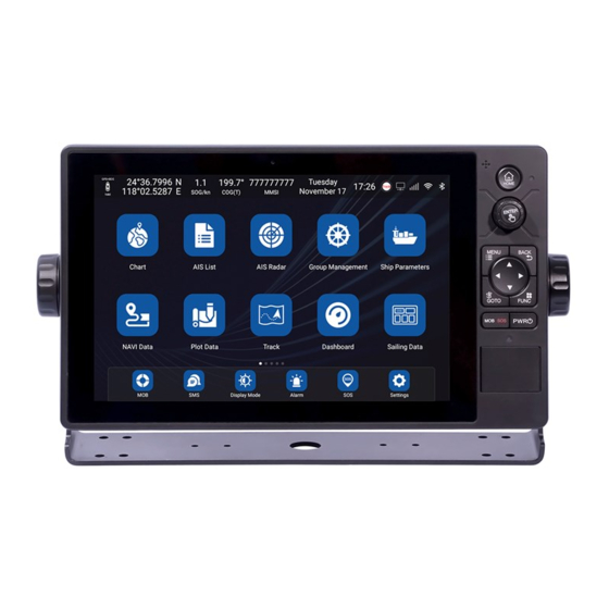
Chapter 2 Operation and Setting [HOME] page When KSD-1100/1210 is powered on, press and hold the [PWR] key ( ) to start up and enter the [HOME] page. Swipe left on the [HOME] page to turn it to the next page. See the following figure for details. -
Page 30: Introduction To The Status Bar
Chapter 2 Operation and Setting KSD-1100/1210 2.1.1 Introduction to the status bar [1] GNSS positioning display mark GNSS positioning normal display: Valid / Not positioning display: Invalid. [2] Display the longitude and latitude coordinates of the ship. Display the longitude and latitude coordinates of the latest positioning when not positioning. -
Page 31: App Fixed Column Introduction
KSD-1100/1210 Chapter 2 Operation and Setting parameter setting. [F] NAVI Data Click to enter the navigation data page. You can select waypoint and route data to quickly call navigation, edit, and add navigation data. [G] Plot Data Click to enter the Plot data page including the drawing Points, Lines, and Polygon. You can select to view, edit, and create new Plot data. -
Page 32: Message Notification Popup
Chapter 2 Operation and Setting KSD-1100/1210 [19] SOS Enter the SOS page, you can quickly broadcast the alarm and distress information through AIS. [20] Settings Click to enter the system settings page, the following item can be set. Version Update / Network/ Func &... -
Page 33: Settings
KSD-1100/1210 Chapter 2 Operation and Setting Settings On the [HOME] page, click [Settings] to go to setting page. 2.2.1 User login On the [HOME] page, click [Settings] to go to setting page and click [Not logged in] to enter the user login page. -
Page 34: Wifi
Chapter 2 Operation and Setting KSD-1100/1210 2.2.2 WIFI You can set the wireless LAN on/off. When it is set to on, select the wireless network you want to connect. And enter the password according to the prompt to connect and use. If the network to be connected is not displayed in the list, you can select [Add network] and enter the network name to add a network. -
Page 35: Sd Upgrade
[1] Format the microSD card (TF card) to FAT32 format [2] Download upgrade package Get the latest download link from Koden to download the upgrade program, including the main , weather, calendar, input method, chart data, and other upgrade program. -
Page 36: General
Chapter 2 Operation and Setting KSD-1100/1210 Note: 1. When the microSD card (TF card) is inserted into the device, the [SD Upgrade] menu will be displayed on the device settings page. 2. Click [SD Upgrade], the device will automatically detect whether there is a new version. Click [Confirm] to open the installation prompt box. -
Page 37: Sound
KSD-1100/1210 Chapter 2 Operation and Setting 2.2.8 Sound [1] Volume: Equipment volume range 0 to 15. [2] Touch tone: You can set the button sound on/off. 2.2.9 Notice You can set the alarm message, short message and AIS message on/off. After the notification message is closed, the message notification pop-up window will be cancelled, and the message reception and voice reminder will not be affected. -
Page 38: Speed And Course Filtering
Chapter 2 Operation and Setting KSD-1100/1210 or off the corresponding output sentence, including, AIS, APB, BOD, BWC, DPT, GGA, GLL, GSA, RMC, VTG, XTE, ZDA, etc. (E) Click [Pause] in Signal check out to pause the input sentence screen to view the output sentence. -
Page 39: Chart
KSD-1100/1210 Chapter 2 Operation and Setting Chart On the [HOME] page, click [CHART] to enter the [CHART] page. The corresponding operation can be carried out on the chart. 2.3.1 Chart Page Data Description [10] [1] Data window: Can independently set and display relevant data information, including Own ship Lat/Lon, Date, SOG COG, HDT, DPT, Wind, Temp and MMSI/NAME. -
Page 40: Data Window
Chapter 2 Operation and Setting KSD-1100/1210 2.3.1.1 Data Window The data window can display relevant data information, including the own ship Lat/Lon, Date, SOG COG, HDT, DPT, Wind, Temp and MMSI/NAME. The Settings box is as shown in the figure below. Click any window to replace the displayed content of the data window. -
Page 41: Measure
KSD-1100/1210 Chapter 2 Operation and Setting [1] North up: The chart is displayed north just above the chart. (Refer to Figure 2.1) [2] Heading/Course up: The chart is displayed with the ship's heading/course up. When there is heading data, the heading up mode is used. When there is no heading data, the course up mode is used. -
Page 42: Center
Chapter 2 Operation and Setting KSD-1100/1210 [1] Distance: Distance between two points. [2] Bearing: Measure the bearing of two adjacent points, that is, the bearing value of the current point relative to the previous point. [3] Total distance: The total distance between the measured points will be displayed on the Operation box. - Page 43 KSD-1100/1210 Chapter 2 Operation and Setting [2] Click [Delete] to exit the operation of adding waypoint. [3] Click [Cancel] to exit the point editing state and return to Figure 2.4 (b). Figure 2.5 (a) point edit page Figure 2.5 (b) Symbol edit page Enter the point edit window, you can edit the attributes of the new point, including the following contents.
-
Page 44: Add Route
Chapter 2 Operation and Setting KSD-1100/1210 2.3.1.7 Add Route On the [CHART] page, long press the position where you want to add a route, and the information page shown in Figure 2.7 (a) will pop up. Click [Add] in this page to confirm the position of the first route node. -
Page 45: Waypoint Navigation Page
KSD-1100/1210 Chapter 2 Operation and Setting [Edit], [NAVI], [Add note], and [Delete], as shown in Figure 2.9. Figure 2.9 Route editing window on the chart 2.3.1.8 Waypoint navigation page When the navigation type is waypoint navigation, the display window on the [CHART] page is shown below. -
Page 46: Chart
Please make sure the C-MAP card is MAX format. b) Please make sure the C-MAP MAX card is inserted on the third card slot of the right side (KSD-1100) or the second card slot of the center side (KSD-1210). - Page 47 KSD-1100/1210 Chapter 2 Operation and Setting b) Click [Chart] on the [HOME] page to enter the Chart page. c) Swipe left from the right edge of the screen or press the [Menu] button to call up the main menu. 0093107081-00...
- Page 48 Chapter 2 Operation and Setting KSD-1100/1210 d )Click [ENC] → click [Chart Management] to enter the page of Chart Management. 2-20 0093107081-00...
- Page 49 KSD-1100/1210 Chapter 2 Operation and Setting e) Click [Chart Update] to pop up the [Local Update] window. f) Click [Install] to install the SA certificate. 0093107081-00 2-21...
- Page 50 Chapter 2 Operation and Setting KSD-1100/1210 g) After the SA certificate is installed, click [Install] again to install unit license. h) After the unit license installation is complete, click [Install] again to install the chart. i) After the installation is completed, click [Update Log] to view the information of update logs.
-
Page 51: Track
KSD-1100/1210 Chapter 2 Operation and Setting j) In the [Chart Unit] page, click [View] to jump to the [CHART] page to view the chart details. 2.3.2.2 Track Click [Track] to enter the track list. For specific operation, refer to the “2.10 Track”. -
Page 52: Mob
Chapter 2 Operation and Setting KSD-1100/1210 2.3.2.6 MOB [1] Click [MOB] to enter the MOB list, refer to “2.13 MOB” for details. [2] Press the [MOB SOS] key, quickly add a MOB point at the current ship position. 2.3.2.7 Display setting Click "Display Setting"... -
Page 53: Own Ship Display
KSD-1100/1210 Chapter 2 Operation and Setting 0.75nm / 0.5nm. [9] Subsea obstruction: Subsea obstruction display switch, the display level can be set, close / 3nm / 1.5nm / 1nm / 0.75nm / 0.5nm. [10] 10m depth contour: 10m depth contour display switch, display level can be set, close / 3nm / 1.5nm / 1nm / 0.75nm / 0.5nm. -
Page 54: Ais Target Display
Chapter 2 Operation and Setting KSD-1100/1210 vector (1 minute position vector, 3 minutes position vector, 6 minutes position vector, 12 minutes position vector). The position vector line can be calculated according to the current speed x time. [4] Position tracking: Provide on / off selection for setting. If set to on, the ship position can be displayed on the screen according to the setting item of [Display Position]. -
Page 55: Ais Information Window
KSD-1100/1210 Chapter 2 Operation and Setting 2.3.2.7.5 AIS information window [1] AIS target display: provide on / off for selection settings. And setting to display or hide all AIS ships on the chart. [2] Display own ship: provide on / off for selection settings, if set to on, display own ship's AIS information [3] AIS ship information window style: Bar Display Window and Card Display Window can be set. -
Page 56: My Data
Chapter 2 Operation and Setting KSD-1100/1210 2.3.2.7.6 My Data Click "My Data" to enter the My Data Settings page. The specific settings are shown below. [1] NAVI Data Display Scale: Set the navigation data to display the level and switch on the chart, setting items, Close / 25nm / 10nm / 5nm / 3nm / 1nm / all. - Page 57 KSD-1100/1210 Chapter 2 Operation and Setting [6] Chart marker map top: When the user map display is turned on, turn on the nautical chart object map top switch to display the nautical chart object icon on top of the user map.
-
Page 58: Ais List
Chapter 2 Operation and Setting KSD-1100/1210 AIS List 2.4.1 AIS list page On the [HOME] page, click [AIS List] to enter the AIS List page. The details are shown in the figure below. [1] ID and Classes Click [Classes] to sort by category A, category B, base station, or navigation aids. - Page 59 KSD-1100/1210 Chapter 2 Operation and Setting [5] Search Click [Search] to enter keywords such as MMSI or ship name in the input box. You can search for ships in the AIS list. [6] Sort Click [Classes], [MMSI], [Name], [COG], [BRG], [SOG], [Distance], [DCPA], [TCPA], [Source] in turn, the list can be switched from top to bottom or sort from bottom to top.
-
Page 60: Ship Parameters
Chapter 2 Operation and Setting KSD-1100/1210 2.4.2 Ship Parameters On the AIS list page, click [Ship Parameters] to enter the own ship parameters page, including navigation parameters and static parameter settings. 2.4.2.1 NAVI Parameter Click [NAVI Parameter] to enter the NAVI Parameter Transmitting editing page, as shown in the figure above. -
Page 61: Static Parameter
KSD-1100/1210 Chapter 2 Operation and Setting 2.4.2.2 Static Parameter Click [Static Parameters] to enter the static parameter page, as shown in the figure above. There are contained the ship's MMSI, ship name, call sign, ship model (see Table 2.1 for specific ship type description), captain (sum of A and B) and ship width (sum of C and D). - Page 62 Chapter 2 Operation and Setting KSD-1100/1210 Table 2.1 Ship type description number ship model number ship model number ship model Hazardous Passenger Undefined Hazardous HSC X ships Z Hazardous Passenger Hazardous HSC Y ships OS Hazardous WIG X Hazardous HSC Z...
-
Page 63: Ais Rader
KSD-1100/1210 Chapter 2 Operation and Setting AIS Rader On the [HOME] page, click [AIS Radar] to go to AIS radar page, as shown in Figure 2.10 below. The AIS radar page displays four distance marking circles fixedly, and the field of view can be adjusted by zooming in or out. -
Page 64: Group Management
Chapter 2 Operation and Setting KSD-1100/1210 (a) This window displays the CPA line with the most dangerous ship that may be encountered. If the cursor selects the AIS target that may be encountered, the corresponding CPA line will be drawn simultaneously for reference. - Page 65 KSD-1100/1210 Chapter 2 Operation and Setting [1] Search Click [Search], enter MMSI or ship name and other keywords in the input box to search for ships in the group. [2] Add Click [Add], select [AIS List] or [Manual Input]. Select AIS list to add, open the AIS list and select the corresponding vessel to add to the fleet.
- Page 66 Chapter 2 Operation and Setting KSD-1100/1210 [3] Edit Click [Edit] to edit the group information, including the group name / display style / move alarm (shift alarm circle) / leave alarm (leave alarm circle) / signal loss alarm / CPA alarm / area alarm / ship type alarm.
-
Page 67: Ship Parameters
KSD-1100/1210 Chapter 2 Operation and Setting alarm switch to reset the alarm circle. (d) Leave alarm: Turn on the leave alarm switch to set the leave alarm circle. Specifically, draw an alarm circle around the ship. The leave alarm is triggered when the position of a ship in the group exceeds the circle in the alarm range. -
Page 68: History Navi
Chapter 2 Operation and Setting KSD-1100/1210 (c) Click on any row of navigation data to edit it. [3] History Navigation: The corresponding data after navigation will be automatically saved in the [History Navigation] list. [4] Search: Enter a number or name keyword to search for waypoints or routes [5] Create navigation data: You can add new navigation data. -
Page 69: Waypoint And Route Operation
KSD-1100/1210 Chapter 2 Operation and Setting [2] View: Select the waypoint, route, or MOB to be viewed. Click [View], the screen will jump directly to the [CHART] page, and the currently selected waypoint, route or MOB will be displayed in the middle of the screen. -
Page 70: Plot Data
Chapter 2 Operation and Setting KSD-1100/1210 [2] Delete navigation data Method 1: Click on the [CHART] page to select the navigation data to be deleted. Click [Delete] in the pop-up operation box to delete the data. Method 2: On the [HOME] page, click the [NAVI Data] button to enter the navigation data list. Swipe the data bar to be deleted to call the [Delete] button. -
Page 71: Plot Data Operation
KSD-1100/1210 Chapter 2 Operation and Setting [5] Filter: You can filter the data in the list by lock / unlock, favorite / unfavorite, point / line / polygon. [6] View: Select the point / line / polygon to be viewed, click [View] to jump to the [CHART] page. The current point / line / polygon is in the middle of the display screen. - Page 72 Chapter 2 Operation and Setting KSD-1100/1210 Figure 2.12 Plotting point editing window Enter the point editing window, you can edit the newly add point, including the following contents. [1] Data selection: Select Point. [2] Type selection: Set Beacon, Hazard marker or Others.
-
Page 73: Add Plot Line
KSD-1100/1210 Chapter 2 Operation and Setting 2.9.2.2 Add plot line Method 1: On the [CHART] page, long press to add the position of the first point, a window will pop up. Click [Add] to determine the position of the first point and click the second position on the chart to determine the second point (refer to Figure 2.13). -
Page 74: Add Plot Polygon
Chapter 2 Operation and Setting KSD-1100/1210 Figure 2.15 plot line new window 2.9.2.3 Add plot polygon Method 1: On the [CHART] page, long press to add the position of the first point, and an information window will pop up. Click [Add] to determine the position of the first point, click the second position on the chart, determine the second point. -
Page 75: Track
KSD-1100/1210 Chapter 2 Operation and Setting Anchorage-prohibited area, Restricted area, Caution area or Others). Select the style, Lock (Unlock), Favorite (Unfavorite), Display (Hide) and input a name. Click [Add] to add, the polygon edit cannot be less than 3 points. Click [List] to select from the plot points and click [Confirm] to save to the plot data list. -
Page 76: Track Record
Chapter 2 Operation and Setting KSD-1100/1210 [3] Add: New track. [4] Filter: You can filter by style, line width, color. [5] Record Mode: Set track record mode, time, RNG or automatic. Select time to set time interval. Select RNG to set distance interval. -
Page 77: Track Color Switch
KSD-1100/1210 Chapter 2 Operation and Setting (a) On the [CHART] page, click to select the track to continue recording, and click the [Track] button in the pop-up operation box to continue the recording of the track. (b) On the [HOME] page, click the [Track] button to enter the track list, and click the [Track] button in the operation bar to the right of the track to continue recording to continue the track record. -
Page 78: Track Deletion
Chapter 2 Operation and Setting KSD-1100/1210 2.10.3 Track deletion You can delete tracks one by one or in batches. The specific operations are as follows. [1] Delete a single track (a) On the [CHART] page, click to select the track to be deleted, and click the [Delete] button in the pop-up operation box to delete the track. -
Page 79: Sailing Data
KSD-1100/1210 Chapter 2 Operation and Setting [2] Click any data frame to switch the display content to the Own ship Lat/Lon, date, DPT, Wind, TEMP, XTE, RNG, BRG, ETA as shown in Figure 2.17 (b) dashboard setting below. Figure 2.17 (a) dashboard setting Figure 2.17 (b) dashboard setting... -
Page 80: Mob
Chapter 2 Operation and Setting KSD-1100/1210 2.13 MOB The water drop mark is used to indicate the location of a person in the boat who has fallen into the water by pressing [MOB SOS] key in an emergency. This function is convenient when turning back by ship to find the person who has fallen into the water. -
Page 81: Display Mode
KSD-1100/1210 Chapter 2 Operation and Setting 2.14 Display mode On the [HOME] page, click [Display Mode] to enter the mode adjustment window. You can adjust the display brightness and volume. And you can set the chart mode and the automatic switching mode. -
Page 82: Sos
Chapter 2 Operation and Setting KSD-1100/1210 [4] New: Click [Contacts] to enter the contact management screen and click [+] to add new member information to the address book. Click [Common Phrases] to enter the Common Phrase Management screen and click [Add Common Phrase] to add common words. -
Page 83: Alarm
KSD-1100/1210 Chapter 2 Operation and Setting 2.17 Alarm On the [HOME] page, click [Alarm] to enter the alarm setting/log window, as shown below. 2.17.1 Ownship Alarm On the alarm page, click [Ownship Alarm] to set the alarm items related to own ship, as shown in the figure above. -
Page 84: Ais Alarm
Chapter 2 Operation and Setting KSD-1100/1210 the center. The alarm is triggered when own ship enters the alarm range of the plot line. Alarm type can be set to bridge, cables and pipes, boundary line or other. [8] Plot Polygon Alarm: Set an alarm radius from the edge of the plot polygon. The alarm is triggered when own ship is within the alarm orientation of the plot polygon. -
Page 85: Alarm Log
KSD-1100/1210 Chapter 2 Operation and Setting 2.17.3 Alarm Log On the alarm setting page, click [Alarm Log] to view the historical alarm records. The specific contents include ID, alarm type, alarm content and alarm time, as shown in the figure below. -
Page 86: Tide
Chapter 2 Operation and Setting KSD-1100/1210 2.19 Tide On the [HOME] page, click [Tide] to enter the tide window. The specific details are shown below. [1] Date: The date of the tide, click to select the tide status at other date. -
Page 87: Calendar
KSD-1100/1210 Chapter 2 Operation and Setting 2.20 Calendar On the [HOME] page, swipe the screen to the left to switch pages, and click [Calendar] to view the calendar. 2.21 Switching Record On the [HOME] page, click [Switching Record] to view the device boot time, last working time, off tie, and working hours, as shown in the following figure. -
Page 88: Video Surveillance
The device supports up to four network cameras, which can be used for video monitoring, video recording, screen capture, mobile monitoring alarm and other functions. KODEN recommends the following manufacturer and model of the Camera to be used. (Camera: Owner supplied) -
Page 89: Video Input Screen
KSD-1100/1210 Chapter 2 Operation and Setting Figure 2-19: Video monitoring connection diagram Note: Camera, Router and LAN cable are owner supplied. Note: Use the router with DHCP settings. 2.22.2 Video input screen After access to the camera, click "Video Surveillance" APP on the [HOME] page to enter the video monitoring screen. - Page 90 Chapter 2 Operation and Setting KSD-1100/1210 (1) Screenshot Click “Screenshot” to capture the page image and save it in the microSD card / TF card of the device, which can be viewed in “2.22.3.2 “Screenshot Management”. (2) Start REC Click "Start REC" and click again to end the recording. The recording is saved in the device and saved in the microSD card of the device, which can be viewed in “2.22.3.1 Video Management”.
-
Page 91: Operation Menu
KSD-1100/1210 Chapter 2 Operation and Setting (5) Close SCRN Click "Close SCRN" to turn on or off the display of the channel image. (6) Full SCRN Click "Full SCRN" to display the monitoring image of the channel in full screen. Click "Split SCRN" to exit the full screen. -
Page 92: Alarm Information Management
Chapter 2 Operation and Setting KSD-1100/1210 2.22.3.3 Alarm Information Management Manage the historical alarm records of the camera, including alarm time, alarm camera name, alarm type, etc. At the same time, you can select the alarm information to delete and other operations. - Page 93 KSD-1100/1210 Chapter 2 Operation and Setting [3] Alarm Setting There are three alarm types of signal disconnection, occlusion screen and video disconnection, which can be set by the user according to the actual use. When the motion detection technology mode is turned on, you can set motion detection or full-time recording.
- Page 94 Chapter 2 Operation and Setting KSD-1100/1210 You can set alarm image formats. If select "Screenshot" for the alarm image format, set the specific "Number of screenshots" and "Screenshot interval". When the alarm is triggered, the corresponding number of screenshots will be captured according to the specific screenshot interval.
-
Page 95: Chapter 3 Specifications
KSD-1100/1210 Chapter 3 Specifications Chapter 3 Specifications Model KSD-1100 KSD-1210 Operation System Android 5.1 with OpenGL ES 3.0 & OpenCL 1.1 Cortex-A17 quad core CPU speed 1.8 GHz 32 bit 2 GB DDR3 1333 MHz Flash memory 16 GB 10.1 inch Capacitive multi touch 21.5 inch Capacitive multi touch... - Page 96 Chapter 3 Specifications SD-1100/1210 Number of AIS 2 channels: receiver Channel A CH87B (161.975MHz), Channel B CH88B (162.025MHz) Output power Rx sensitivity < -107 dBm @ PER<20% *: MicroSD card slot or TF card slot 0093107081-00...
Need help?
Do you have a question about the KSD-1100 and is the answer not in the manual?
Questions and answers