
Related Manuals for APM APM-SP-VDC-3U Series


Summary of Contents for APM APM-SP-VDC-3U Series
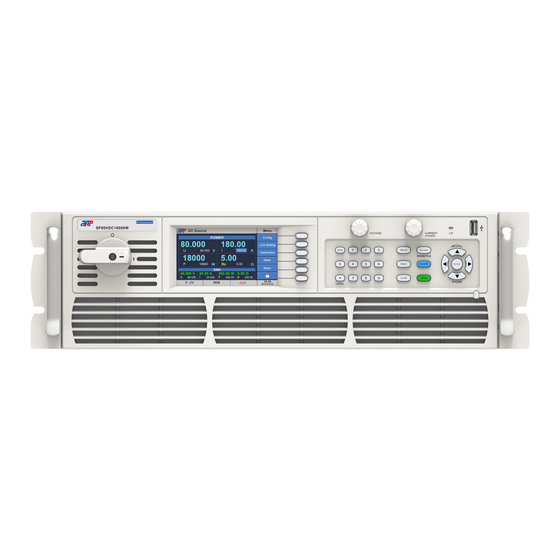
- Page 1 APM TECHNOLOGIES PROFESSIONAL INNOVATIVE BRANDING SERVICE en.apmtech.cn High Power DC Power Supply User Manual...
-
Page 3: Table Of Contents
Contents Part NO. 18950-745-00 Contents Preface ........................... 05 Safety Notices ........................1 About this Manual ......................Scope ............................Targeted Audience ....................... Use of this Manual and Legal Notices ................. 2 Unpacking ......................... Scope of delivery ......................Options ........................Checking for Shipping Damage ................... 2.4 Product Damage or Failure Repair ................ - Page 4 Contents 5 Menu Operation ........................ 5.1 Menu Structure ......................8 5.2 Main Screen ........................21 5.3 Navigation Page......................22 5.4 Operation Modes Introduction ..................22 5.5 Setting Menu ........................ 23 5.5.1 Power/Sink Function....................23 5.5.2 More Setting ......................24 5.5.2.1 Vdc S/R ....................... 24 5.5.2.2 Idc S/R ......................
- Page 5 Contents 5.7.1.1.4 LAN Setting ................. 34 5.7.1.1.5 CAN Setting ................. 34 5.7.1.2 System Setup .................... 35 5.7.1.2.1 Buzzer ..................35 5.7.1.2.2 P/O Sta..................35 5.7.1.2.3 P-Out .................... 36 5.7.1.3 EXT Control ....................36 5.7.1.3.1 Setup .................... 36 5.7.1.3.2 Monitor ..................37 5.7.1.4 System Info.
- Page 6 Contents Parallel/Series ........................6.1 Configuring All Slave Units ..................57 6.2 Configuring The Master Unit ..................58 Parallel Mode Connection Diagram ................60 Series Mode Connection Diagram ................7 Calibration ......................... 7.1 Calibration Equipment required .................. 62 7.2 Calibration Equipment Setup ..................
-
Page 7: Preface
Thank you for using this series High Power DC Power Supply, a product developed & manu- factured by APM Technologies. We sincerely hope this product will meet your needs. The sections outlined in this user manual are suitable for the following product models. -
Page 8: Safety Notices
Safety Notices Safety Notices Warning! This symbol highlights operations that have the potential to endanger users, operation proce- dures and instruction must be absolutely understood before use. Caution! This symbol highlights precautions users need to take to avoid potential injury during equipment operation. -
Page 9: About This Manual
Please check for updates at en.apmtech.cn and download the latest version of this manual and information. It is prohibited in any way to use all or part of the firmware or software developed by APM Technologies for other commercial purposes. It is prohibited to decompile, decrypt or otherwise damage the software developed by APM Technologies. -
Page 10: Unpacking
Unpacking Unpacking 2.1 Scope of delivery The following accessories are included with each DC power supply. See table below for reference. Item Item Included Quantity Power supply device Rack mount Handles (removable) Screws to install Rack mount Handles 1 set RS232 Serial Cable USB Cable Quick Guide... -
Page 11: Checking For Shipping Damage
2.4 Product Damage or Failure Repair In the unlikely event of product failure, please promptly contact APM Technologies or its dealer and provide the serial number of the faulty DC power supply, detailed fault information and pictures to help us identify the cause of the failure. -
Page 12: Products Introduction
Solar panel I-V curve simulation function. ● Smart 3-stage charging algorithm simulation. ● Battery simulator function. ● Continuous source & sink function , with APM DC E-load to expand loading capability. ● List/Step mode programming. ● TTL/Analog control and monitoring. ●... -
Page 13: Operation Instructions
Products Introduction 3.3 Operating Instructions This product is a precision instrument, please read this manual carefully before use. In order to ensure measurement accuracy it is recommended that a calibration check be performed on this product every year. 3.4 Operating Environments 1. -
Page 14: Fuse
Products Introduction Caution! The protective safety earth/ground connection must connect first and disconnect after the AC line and neutral wires. All approved AC power connectors are designed to meet this requirement. If the input wires are directly connected to an AC mains circuit assure that the AC source is deactivated prior to making or disconnecting the connection. -
Page 15: Start Procedure
4. OK EEPROM Check Please contact APM CS engineer for support if there is any failed item in this self-checking page. The diagnostics will take several seconds to complete. If all results are OK, the unit will revert to the default main screen. -
Page 16: Panel Description
Panel Description Panel Description 4.1 Front Panel Description Power Switch For 3U models, rotate power switch clockwise to turn on the unit. Rotate power switch count- erclockwise to turn off the unit. The 6U product is fitted with a mains input circuit breaker on the top left-hand side of the front panel. - Page 17 Panel Description Color touch screen The color LCD touch screen displays all settings, measurements, menus and warning message. It may also be used to enter parameter values and settings by using its touch screen function. The user can use his fingertip or the built-in stylus inside the front panel directly to control the unit.
- Page 18 Panel Description Note If the front panel is locked (Lock is set to ON), the shuttle knob is disable. Numeric and functional keys Decimal Keypad Keys Purpose Manual Reference [ESC] Back to previous screen or entry Allow direct entry of parameter values [0]~[9] Decimal point key/Keypad unlock function key or press [.] / ( [LOCAL] )
-
Page 19: Rear Panel Description
Panel Description 4.2 Rear Panel Description LAN & GPIB communication interface (optional) . External TTL/Analog control interface. System Bus, for master/slave system data transmission. Termination resistor CAN-R. Vs+/Vs- remote sense connections. DC output negative/positive terminal. AC mains input connector. These interface option installs in place of the standard RS485/RS232/USB interface, occupies the same physical slot. -
Page 20: Menu Operation
Menu operation Menu Operation 5.1 Menu Structure The table below shows the entire menu system at once. Each section will be covered in subsequent sections in more detail. There are three levels of nested menu under the Main Screen. The main screen is always the first screen displayed after the power source is turned on. - Page 21 Menu operation Load-2QO Sink On/Off Waveform Limitation Vlimit Set the maximum voltage Vlimit-H/V Set the minimum voltage Vlimit-L/V Ilimit Set the maximum current Ilimit-H/A Set the minimum current Ilimit-L/A Plimit Plimit-H/W Set the maximum power Set the minimum power Plimit-L/W Rlimit Set the maximum output programmable resistance Rlimit-H/Ω...
- Page 22 Menu operation Menu Description Menu Config Remote Setup RS232 Set the communication parameters for RS232 RS485 Set the communication parameters for RS485 Enable the communication port and set the address USB/GPIB Ethernet setting Address and baudrate setting System Setup Buzzer ON (enable) or OFF (disable) the buzzer function P-out Set the output as last shutdown setting or OFF...
-
Page 23: Main Screen
Menu operation Menu Description Output Mode PLD Testing List Mode Load Load the list settings to the unit Edit Edit the list files Program Load Load the program settings to the unit Edit Edit the program files Step Load Load the step settings to the unit Edit the step files Edit Special Func... -
Page 24: Navigation Page
Menu operation Output settings and measurement zone for Power mode There are four output parameters can be set in this area, including Voltage, Current, Power and programmable output resistance. The sink function will display only after it is enabled. Output settings and measurement zone for Sink mode There are four input parameters can be set in this area, including Voltage, Current, Power and Resistance. -
Page 25: Operation Modes Introduction
Menu operation 5.4 Operation Modes Introduction This series power supply supports three operation modes, including Local operation mode, Remote operation mode and External analog control mode. The first two operation modes can be selected by a connected computer without affecting the power supply output. Under Remote control mode, all front panel keys except the decimal point key are locked. -
Page 26: More Setting
Menu operation After selecting Power+Sink mode, both the Power and Sink are displayed in the main screen. 5.5.2 More Setting This screen allows control over the following output setting using these soft keys. ● Vdc S/R ● Idc S/R ● Average ●... -
Page 27: Idc S/R
Menu operation 5.5.2.2 Idc S/R This menu allows the user to set the slew rate for Idc, which including: Enable, enable the slew rate setting. Rise-A/ms, used to set the current rise slew rate. Fall-A/ms, used to set the current fall slew rate. 5.5.2.3 Average The Average soft key changes the number of the time a reading is averaged before the corre- sponding measurement parameter display is updated. -
Page 28: Cc/Cv Prior
Menu operation 5.5.2.4 CC/CV Prior This menu provides CC/CV priority function allows the user to select suitable mode correspond to test requirement, let the output be voltage high speed (CV Prior) or current no overshoot (CC Prior) mode. Available setting range for delay time is from 0.001s through 10s. 5.5.2.5 Hi-Variation There is a internal dummy load that can be enabled to increase the speed of the voltage fall time for high speed test applications. -
Page 29: Waveform
Menu operation Press the Disp 1 of 2 soft key to turn to the next page. 5.5.5 Waveform The Waveform soft key displays a visual time domain representation of the output. 5.5.6 Limitation The limitation soft key displays the user limit setting screen. User limits are useful to protect a unit under test from operator error by setting the upper and or lower parameter value limits. -
Page 30: Ilimit
Menu operation 5.5.6.2 Ilimit This menu allows the user to set the upper and or lower parameter value limits for current. 5.5.6.3 Plimit This menu allows the user to set the upper and or lower parameter value limits for power. 5.5.6.4 Rlimit This menu allows the user to set the upper and or lower parameter value limits for the output programmable resistance. -
Page 31: Protection
Menu operation 5.5.7 Protection The protection functions that can be configured from this screen only apply to user programmable protections. All hardware protection functions such as temperature (OTP) always enabled and cannot be edited. To edit any protection setting, select the relevant field and enter a new value using [0]~[9] keys or the on-screen decimal keypad. -
Page 32: Opp
Menu operation 5.5.7.3 OPP The OPP setting range is from 0.0W through 1.10 x Rated power. The delay time setting is from 0.001s through 10s. 5.5.7.4 UVP The UVP setting range is from 0.0V through 1.10 x Rated voltage. The delay time setting is from 0.001s through 10s. -
Page 33: Lock
Menu operation 5.5.8 Lock The front panel keys and touch screen function can be locked to prevent unwanted changes to output settings and power source configuration. A LOCK symbol will be displayed at the last soft key to indicate this key board lock state. To unlock the keyboard and touch screen, press the decimal key [.] on the numeric key pad. -
Page 34: Remote Setup
Menu operation 5.7.1.1 Remote Setup The remote setup screen provides access to all six available remote communication interfaces: ● RS232 ● RS485 ● USB/GPIB ● ● To configure each interface, press the corresponding soft key and use the cursor or touch screen to adjust parameters as needed. -
Page 35: Rs485 Settings
Menu operation 5.7.1.1.2 RS485 Settings From the Remote Setup screen, press the RS485 soft key to change RS485 interface settings. Directly select through Baudrate, Parity, Stop bits and Addr fields to set the desired values. Press the [Esc] key when done to back up to the Remote Setup screen. Parameter ranges are: Enable, enables RS485 communication mode. -
Page 36: Lan Setting
Menu operation 5.7.1.1.4 LAN Setting From the Remote Setup screen, press the LAN soft key to change LAN interface settings. Press the [Esc] key when done to back up to the Remote Setup screen. Parameter ranges are: Enable, enables LAN communication mode. ETH Setting, Auto, Manual, to set DCHP mode (Auto) or use Manual to assign a fixed IP address. -
Page 37: System Setup
Menu operation Parameter ranges are: Enable, enables CAN communication mode. BaudRate, 10K, 100K, 250K, 400K, 500K. Addr, 0~127. 5.7.1.2 System Setup The System setting screen is used to configure the following resources of the power source: ● Buzzer ● P/O Sta. ●... -
Page 38: P-Out
Menu operation 5.7.1.2.3 P-Out The P-Out can control the output state of the power supply, where, Last, the power supply will store the last setting of the output in effect when powered off and recall this same setting at power on. OFF, the output of the power supply will keep off at power on. -
Page 39: Monitor
Menu operation Parameter ranges are: EXT Control, enable or disable the external control mode through this menu. VREF, the input gain can be set to 5V or 10V. DI, digital input. EXT-EN, enables the external control mode through the high or low level input. Set to low level will enable external control directly. - Page 40 Menu operation Analog Interface Specification Name Type* Description Default levels Electrical specification EXT-ON DC output Active high; Voltage range=0~30V, U <1V; ON/OFF Low level<1V; =-1mA bei5V; U low to high typ High level>4V; Sender: Open collector against DGND Vset Set voltage 0~10V or 0~5V correspond Accuracy: <0.2%U value...
- Page 41 Menu operation Pin Name Type* Description Default levels Electrical specification Overvoltage Alarm OVP=High, U >4V; Quasi open collector with pull-up high alarm No alarm OVP=Low, against Vcc (approx. 10V). With 5V on <1V; the pin max. flow +1mA. I =-10mA at UCE=0.3V, U =30V.
- Page 42 Menu operation Application examples 1) Enable the external control with low level Change the signal polarity setting of 'EXT-EN' to 'L' in the menu accordingly will enable external control mode directly. Note: This external control of the pin is prior than the menu setting. That means this function will be activated even the EXT Control menu set as Disable.
- Page 43 Menu operation 2) Example with external voltage source/potentiometers control Consider the input voltage ranges to select the input reference voltage (VREF), 5V or 10V. Then adjust the external voltage input (0~5V) or external potentiometer (0~5kΩ or 0~10kΩ) to remotely adjust the power supply voltage and current regulation settings. 3) Reading the actual values Consider the standard multimeter range to select the Output reference voltage (VREF), 5V or 10V.
-
Page 44: System Info
Menu operation 5.7.1.4 System Info. This screen is for information only. For remote service and diagnostics, the user may be asked to provide some of the information shown here to assist customer service. None of this data can be edited by the user. 5.7.1.5 Run Info. -
Page 45: Display
Menu operation 5.7.2.1 Display The two soft keys in this screen control LCD brightness adjustment. The brightness can be adjusted up Brightness+ or down Brightness-. Adjust the display brightness as needed. for best viewing experience. 5.7.2.2 Date/Time The power source has a real-time date and time clock , which is set at the factory at the time of shipment but will have to be adjusted for local date and time zone. -
Page 46: Other
Menu operation 5.7.4 Other The Other setting screen contains miscellaneous system settings. The following items can be configured from this screen: ● Recall Def ● Warning Log ● Firmware Upd 5.7.4.1 Recall Def The Recall Default screen can be used to recall original factory (default) settings. Doing so will erase the current setup and replace it with default values. -
Page 47: Firmware Upd
This screen is used to perform a firmware update. Firmware updates should only be installed when they can eliminate existing bugs in the firmware in the device or contain new features. APM CS team will provide the files if needed accordingly. 5.8 Store/Recall The Store/Recall screen is used to manage power supply setups. -
Page 48: Output Mode
Menu operation 5.9 Output Mode The Output Mode screen provides access to select special functions and built-in test modes. Some of these functions are only available on the Professional version models. The following Soft Keys are available in the Output Mode screen to access these functions: ●... - Page 49 Menu operation This will bring up the list edit screen where the steps in the list can be added and edited. Parameter ranges are: Format, including three options, Rectangle, S-Ramp and F-Ramp. Supports different quantity parameters setting. NO., List file NO. Step Count, set the total steps of the current list file, which setting range is from 1 through 8.
- Page 50 Menu operation Press the Load soft key to download all the settings to the unit. Then the page will jump to the following screen. Parameter ranges are: NO., select the list file. Repeat, setting the repeat count of the selected list file. A zero repeat count indicates infinite looping.
-
Page 51: Program Mode
Menu operation 5.9.1.2 Program mode The Program mode allows the user to edit the long output sequence with the already edited list files. Press the Edit soft key to enter edit mode. Parameter ranges are: PRO NO., Program file NO. Step Count, set the total steps of the current list file, which setting range is from 1 through 18. -
Page 52: Step Mode
Menu operation Press the Load soft key to download all the settings to the unit. Then the page will jump to the following screen. Parameter ranges are: NO., select the program file. Repeat, setting the repeat count of the selected program file. A zero repeat count indicates infinite looping. - Page 53 Menu operation Press the Edit soft key to enter edit mode. Parameter ranges are: Step NO., Step file NO. Count, set the repeat count. ∆T, dwell time between steps. Sweep, power sweep function enable or disable. Save, save edits to the memory when done. When the Step edit are complete, press the Save soft key to save all changes made to the step file.
-
Page 54: Special Func
Menu operation The running state updates regularly while the step transient is running, which including already executed repeat times, test time and remaining time. Sweep Mode The step transient is useful for checking the efficiency of a power supply can capturing the voltage, current and power at the maximum power operating point. -
Page 55: Test Mode
Menu operation 5.9.2.1 Test Mode The Test Mode compares measurement values against a user defined set of measurement limits and shows a PASS or FAIL result in one or more measurements are out of range. This type of limit testing is useful for production test applications. 5.9.2.2 LV Mode Users can enable LV mode to reduce the output voltage ripple at low voltage range. -
Page 56: Mcurr Share
Menu operation 5.9.2.4 MCurr Share Enable this function will keep output current balance between power modules in one chassis. 5.9.2.5 Timer Func There are two timer control modes under this menu. Power ON Timer, when this timer function is ON, it will activate the timer. After timer setting is made, press the [ESC] key to return to the main screen. -
Page 57: Counting Func
Menu operation Power OFF Timer, when this timer function is ON, it will activate the timer. After timer setting is made, press the [ESC] key to return to the main screen. After setting up the output current & voltage and press [On/Off] to output, the screen will show the countdown of the timer. Once it reaches down to zero, the supply will turn off the output automatically. -
Page 58: Language
Menu operation In Current counting mode, set the basic output parameters according to test requirement. Press [1]~[9] and [Enter] keys to set IL, which is the cut-off current for counting. Ib, the breaker or fuse current. After the setting, press the [On/Off] key to turn on the output. The count starts from when output current has reached Ib setting and stop until the breaker or fuse is open, when the output current is less than IL setting. -
Page 59: Parallel/Series
Parallel/Series Parallel/Series Two or more this series power supplies can be configured in Master/Slave mode to increase output current or voltage. Parallel mode, up to 16 units, to increase output power & current. Series mode, up to 2 units, to increase output voltage. Warning! DO NOT connect units in both series and parallel mode at the same time. -
Page 60: Configuring The Master Unit
Parallel/Series Slave - Slave1 The slaves can no longer be controlled manually or remotely, neither via the analog nor via digital interfaces. Note: The Salve unit can also be unlocked using the [.] key on the front panel. 6.2 Configuring The Master Unit Tap on Parallel/Series icon on Navigation page to enter Master/Slave setting menu. - Page 61 Parallel/Series Searching Then switch to the main page if the detected number of slaves is equal to expected. The display on the master unit changes after initialization and all set values are reset. The master now displays the set and actual values of the total system. Depending on the number of units and output connection, the total current or voltage and power will multiply.
-
Page 62: Parallel Mode Connection Diagram
Parallel/Series 6.3 Parallel Mode Connection Diagram Load System Bus Communication Cable It doesn't matter which of the two master-slave connection sockets (RJ45) is connected to the next unit. Termination Resistor CAN-R Flip dip switch 1 to ON (down) position. Remote Sensing Wires Use remote sensing in applications where load regulation at the load is critical. -
Page 63: Series Mode Connection Diagram
Parallel/Series 6.4 Series Mode Connection Diagram System Bus Communication Cable It doesn't matter which of the two master-slave connection sockets (RJ45) is connected to the next unit. Termination Resistor CAN-R Flip dip switch 1 to ON (down) position. Remote Sensing Wires Use remote sensing in applications where load regulation at the load is critical. -
Page 64: Calibration
Calibration Calibration All APM instruments are factory calibrated prior to shipment. The recommended calibration interval for this series power supply is one year. Calibrate only as needed. 7.1 Calibration Equipment required The following equipment is required to perform calibration on any of this series power supplies. -
Page 65: Calibration Procedure
Calibration 7.3 Calibration Procedure The power source can be calibrated from the front panel. There are no manual calibration adjustment inside the unit so there is no need to remove the top cover. The following items require routine calibration: U Set&Meas, to calibrate output voltage setting and measurement. I Set&Meas, to calibrate output current limit setting and measurement. -
Page 66: Voltage Setting & Measurement Calibration
Calibration 7.3.2 Voltage Setting & Measurement Calibration Note Please make sure there is NO load connection when calibrating voltage setting and mea- surement. Press the U Set&Meas soft key. There are only two calibration points under this menu. The low voltage range will be calibrated first. -
Page 67: Current Setting & Measurement Calibration
Calibration 7.3.3 Current Setting & Measurement Calibration Note Please make sure the load in connected (switch is closed) before calibration. Set the proper voltage and current based on the specification range of the calibration instruments. Apply the calculate resistor to make sure the power supply will work under CC mode during current calibration. -
Page 68: Power Setting & Measurement Calibration
Calibration Note: The recommended range for low current range calibration point (IL) is from 2% to 18% rated current, and for high current range calibration point (IH) is from 82% to 98% rated current. 7.3.4 Power Setting & Measurement Calibration Note It is recommended to use calculated value (voltage times current) instead of Power meter reading value due to the high current range. -
Page 69: Installation
Installation Installation 8.1 Product Dimensions 423.0 423.0 30.0 30.0 483.0 483.0 Dimensions of 3U Models (mm) Dimensions of 6U Models (mm) 8.2 Installing Rack Mount Handles Caution! The handles on the front side of the device are not for carrying! Install the rack mount handles provide in the ship kit on the power source before mounting the unit in an instrument rack. -
Page 70: Installation Of An Optional Interface Card
Installation 8.3 Installation of An Optional Interface Card Caution! Common ESD protection procedures apply when inserting or exchanging an interface card. The unit must be switched off before insertion or removal of an interface card. Never insert any other hardware other than a specified interface card. It is strongly recommended that the slot cover must be mounted in order to avoid internal dirtying of the device and possible shock hazard. -
Page 71: Shelf Mounting Diagram Of The Unit
Installation 8.4 Shelf Mounting Diagram of The Unit This series power supply can be mounted in a standard 19-inch rack panel or cabinet. If using rack-mount slides, the user can select the optional rack-mount slide kit at the same time, to install the unit in a standard 19-inch equipment rack. -
Page 72: Input Connection
Installation 8.5 Input Connection Warning! Connection to the AC input may only be carried out by qualified personnel! It is suggested to use an external circuit breaker which protects, and can disconnect all the current carrying conductors for the AC input cable. Be sure to disconnect the AC mains before accessing the AC input. - Page 73 Installation For the input voltage at 208V Input Nominal Breaker Power Wire Size Imax Wire Size Imax Wire Size Imax 12kW 16mm 16mm 16mm 18kW 16mm 16mm 16mm 100A 24kW 25mm 25mm 103A 25mm 103A 125A 125A 103A 103A 30kW 25mm 25mm 25mm...
-
Page 74: Connection To Dc Loads
Installation This series power supply can have from one to three internal 6kW power blocks, each of which is connected across a separate phase of the 3-phase AC mains. The following figures illustrate how to install three 6kW units or three 12kW units in order to obtain a balanced current draw on the 3-phase AC mains. - Page 75 Installation Please refer to the table below to select cable size. Also consider temperature rating of the copper wires and voltage drop to the load. Minimum Conduct Sizes Minimum Conduct Sizes Rated Current Rated Current Nominal Cross Nominal Cross of equipment (A) of equipment (A) -sectional Area -sectional Area...
-
Page 76: Remote Sensing
Installation 8.7 Remote Sensing Note For a single power module, if the output power exceeds 6300, an alarm information will pop up on the screen. Sense cables should be twisted and laid close to the DC cables to damp oscillation. The + sense cable must be connected to + output terminal or + load terminal, while the - sense wire terminal must be connected to - output terminal or - load terminal. -
Page 77: Recycling And Disposal
If you have any questions about the High Power DC Power Supply, please contact us. We will be happy to answer any of your questions. Below are our contact details: APM Technologies Add: # 7, Link Information Industry Park, Shuilianshan Road, Nancheng, Dongguan,... -
Page 78: Appendix A Specifications
Appendix A Specifications Appendix A Specifications MODEL SP80VDC6000W SP80VDC12000W SP80VDC18000W Input 187~253VAC Voltage 340~460VAC 3P208 L1-0, L2,L3-38A 3P208 L1-60A, L2,L3-38A 3P208 L1,L2,L3-60A Current 3P400 L1-0, L2,L3-19A 3P400 L1-30A, L2,L3-19A 3P400 L1,L2,L3-30A 45~65Hz Frequency Connection 2ph, PE 3ph, PE 3ph, PE T50A*2pcs Fuse (Internal) T30A*2pcs... - Page 79 Appendix A Specifications MODEL SP80VDC6000W SP80VDC12000W SP80VDC18000W <0.2%Imax(198mA) <0.2%Imax(396mA) <0.2%Imax(594mA) CC Accuracy <4mV CV Resolution <0.1%Umax(80mV) CV Accuracy CP Resolution 0.5W CP Accuracy <0.5%Pmax(1625mW) <0.5%Pmax(3250mW) <0.5%Pmax(5000mW) Slew Rate 0.01~2.5A/us Dynamic Mode 20ms~50s General 4.3” Color touch LCD Graphic Display Operation Key Feature Soft keys, Numberic keys, Rotary knod, USB port for transfer and upgrading firmware Rack Mount Handles Temperature control...
- Page 80 Appendix A Specifications MODEL SP80VDC24000W SP80VDC30000W SP80VDC36000W Input 200~253VAC Voltage 340~460VAC 3P208 L1-60A, L2,L3-103A 3P208 L1-125A,L2,L3-103A 3P208 L1,L2,L3-125A Current 3P400 L1-30A, L2,L3-49A 3P400 L1-63A,L2,L3-49A 3P400 L1,L2,L3-63A Frequency 45~65Hz 3ph, PE Connection T50A*2pcs Fuse (Internal) T30A*2pcs >0.99 Power Factor 28.8kVAmax 36kVAmax 43.2kVAmax Input Power 3P208 ~90.5%@80V, 3P208 ~86.5%@800A...
- Page 81 Appendix A Specifications MODEL SP80VDC24000W SP80VDC30000W SP80VDC36000W CC Accuracy <0.2%Imax(792mA) <0.2%Imax(990mA) <0.2%Imax(1188mA) <4mV CV Resolution CV Accuracy <0.1%Umax(80mV) CP Resolution 0.5W CP Accuracy <0.5%Pmax(6500mW) <0.5%Pmax(8000mW) <0.5%Pmax(10000mW) Slew Rate 0.01~2.5A/us Dynamic Mode 20ms~50s General 4.3” Color touch LCD Graphic Display Operation Key Feature Soft keys, Numberic keys, Rotary knod, USB port for transfer and upgrading firmware Rack Mount Handles Temperature control...
- Page 82 Appendix A Specifications MODEL SP165VDC12000W SP165VDC24000W Input 187~253VAC 200~253VAC Voltage 340~460VAC 3P208 L1-60A, L2,L3-38A 3P208 L1-125A,L2,L3-103A Current 3P400 L1-30A, L2,L3-19A 3P400 L1-63A,L2,L3-49A Frequency 45~65Hz Connection 3ph, PE T50A*2pcs Fuse (Internal) T30A*2pcs >0.99 Power Factor Input Power 14.5kVAmax 29kVAmax 3P208 ~90.5%@165V, 3P208 ~85%@180A 3P208 ~90.5%@165V, 3P208 ~85%@360A Efficiency 3P400 ~91.5%@165V, 3P400 ~85.5%@180A...
- Page 83 Appendix A Specifications MODEL SP165VDC12000W SP165VDC24000W Interface RS232/RS485/USB(Standard), GPIB/LAN(Optional), CAN(Optional) <3ms Command Response Time Analog Interface(Optional) Analog input 0~5V/0~10V or 0~5kΩ/0~10kΩ to set 0~105% voltage, current and power Set Value Inputs Actual Value Output Analog output 0~5V/0~10V to monitor the voltage and current. Accuracy U/I/P/R <0.2% F.S Actual Output U/I...
- Page 84 Appendix A Specifications MODEL SP250VDC18000W Input 190~253VAC Voltage 340~460VAC 3P208 L1,L2,L3-60A Current 3P400 L1,L2,L3-30A Frequency 45~65Hz Connection 3ph, PE T50A*2pcs Fuse (Internal) T30A*2pcs >0.99 Power Factor Input Power 21.75kVAmax 3P208 ~90.5%@250V, 3P208 ~85%@180A Efficiency 3P400 ~91.5%@250V, 3P400 ~85.5%@180A Output Voltage Range 0~250V Current Range 0~180A...
- Page 85 Appendix A Specifications MODEL SP250VDC18000W Interface RS232/RS485/USB(Standard), GPIB/LAN(Optional), CAN(Optional) <3ms Command Response Time Analog Interface(Optional) Set Value Inputs Analog input 0~5V/0~10V or 0~5kΩ/0~10kΩ to set 0~105% voltage, current and power Actual Value Output Analog output 0~5V/0~10V to monitor the voltage and current. Accuracy U/I/P/R <0.2% F.S Actual Output U/I...
- Page 86 Appendix A Specifications MODEL SP500VDC6000W SP500VDC12000W SP500VDC18000W Input 187~253VAC Voltage 340~460VAC 3P208 L1-0, L2,L3-38A 3P208 L1-60A, L2,L3-38A 3P208 L1,L2,L3-60A Current 3P400 L1-0, L2,L3-19A 3P400 L1-30A, L2,L3-19A 3P400 L1,L2,L3-30A Frequency 45~65Hz Connection 2ph, PE 3ph, PE 3ph, PE T50A*2pcs Fuse (Internal) T30A*2pcs >0.99 Power Factor...
- Page 87 Appendix A Specifications MODEL SP500VDC6000W SP500VDC12000W SP500VDC18000W <0.2%Imax(32mA) <0.2%Imax(64mA) <0.2%Imax(96mA) CC Accuracy <4mV CV Resolution <0.1%Umax(500mV) CV Accuracy CP Resolution 0.5W CP Accuracy <0.5%Pmax(1625mW) <0.5%Pmax(3250mW) <0.5%Pmax(4875mW) Slew Rate 0.01~2.5A/us Dynamic Mode 20ms~50s General 4.3” Color touch LCD Graphic Display Operation Key Feature Soft keys, Numberic keys, Rotary knod, USB port for transfer and upgrading firmware Rack Mount Handles Temperature control...
- Page 88 Appendix A Specifications MODEL SP500VDC24000W SP500VDC30000W SP500VDC36000W Input 200~253VAC Voltage 340~460VAC 3P208 L1-60A, L2,L3-103A 3P208 L1-125A,L2,L3-103A 3P208 L1,L2,L3-125A Current 3P400 L1-30A, L2,L3-49A 3P400 L1-63A,L2,L3-49A 3P400 L1,L2,L3-63A Frequency 45~65Hz Connection 3ph, PE T50A*2pcs Fuse (Internal) T30A*2pcs >0.99 Power Factor Input Power 28.8kVAmax 36kVAmax 43.2kVAmax...
- Page 89 Appendix A Specifications MODEL SP500VDC24000W SP500VDC30000W SP500VDC36000W <0.2%Imax(128mA) <0.2%Imax(160mA) <0.2%Imax(192mA) CC Accuracy <4mV CV Resolution <0.1%Umax(500mV) CV Accuracy CP Resolution 0.5W CP Accuracy <0.5%Pmax(6500mW) <0.5%Pmax(8125mW) <0.5%Pmax(9750mW) Slew Rate 0.01~2.5A/us Dynamic Mode 20ms~50s General 4.3” Color touch LCD Graphic Display Operation Key Feature Soft keys, Numberic keys, Rotary knod, USB port for transfer and upgrading firmware Rack Mount Handles Temperature control...
- Page 90 Appendix A Specifications MODEL SP750VDC6000W SP750VDC12000W SP750VDC18000W Input 187~253VAC Voltage 340~460VAC 3P208 L1-0, L2,L3-38A 3P208 L1-60A, L2,L3-38A 3P208 L1,L2,L3-60A Current 3P400 L1-0, L2,L3-19A 3P400 L1-30A, L2,L3-19A 3P400 L1,L2,L3-30A Frequency 45~65Hz Connection 2ph, PE 3ph, PE 3ph, PE T50A*2pcs Fuse (Internal) T30A*2pcs >0.99 Power Factor...
- Page 91 Appendix A Specifications MODEL SP750VDC6000W SP750VDC12000W SP750VDC18000W <0.2%Imax(20mA) <0.2%Imax(40mA) <0.2%Imax(60mA) CC Accuracy <4mV CV Resolution <0.1%Umax(750mV) CV Accuracy CP Resolution 0.5W CP Accuracy <0.5%Pmax(1625mW) <0.5%Pmax(3250mW) <0.5%Pmax(4875mW) Slew Rate 0.01~2.5A/us Dynamic Mode 20ms~50s General 4.3” Color touch LCD Graphic Display Operation Key Feature Soft keys, Numberic keys, Rotary knod, USB port for transfer and upgrading firmware Rack Mount Handles Temperature control...
- Page 92 Appendix A Specifications MODEL SP750VDC24000W SP750VDC30000W SP750VDC36000W Input 200~253VAC Voltage 340~460VAC 3P208 L1-60A, L2,L3-103A 3P208 L1-125A,L2,L3-103A 3P208 L1,L2,L3-125A Current 3P400 L1-30A, L2,L3-49A 3P400 L1-63A,L2,L3-49A 3P400 L1,L2,L3-63A Frequency 45~65Hz Connection 3ph, PE T50A*2pcs Fuse (Internal) T30A*2pcs >0.99 Power Factor Input Power 28.8kVAmax 36kVAmax 43.2kVAmax...
- Page 93 Appendix A Specifications MODEL SP750VDC24000W SP750VDC30000W SP750VDC36000W <0.2%Imax(60mA) <0.2%Imax(75mA) <0.2%Imax(90mA) CC Accuracy <4mV CV Resolution <0.1%Umax(750mV) CV Accuracy CP Resolution 0.5W CP Accuracy <0.5%Pmax(6000mW) <0.5%Pmax(7500mW) <0.5%Pmax(9000mW) Slew Rate 0.01~2.5A/us Dynamic Mode 20ms~50s General 4.3” Color touch LCD Graphic Display Operation Key Feature Soft keys, Numberic keys, Rotary knod, USB port for transfer and upgrading firmware Rack Mount Handles Temperature control...
- Page 94 Appendix A Specifications MODEL SP1000VDC12000W SP1000VDC24000W Input 187~253VAC 200~253VAC Voltage 340~460VAC 3P208 L1-60A, L2,L3-38A 3P208 L1-60A, L2,L3-103A Current 3P400 L1-30A, L2,L3-19A 3P400 L1-30A, L2,L3-49A Frequency 45~65Hz Connection 3ph, PE T50A*2pcs Fuse (Internal) T30A*2pcs >0.99 Power Factor Input Power 14.5kVAmax 29kVAmax 3P208 ~92%@1000V, 3P208 ~90%@32A 3P208 ~92%@1000V, 3P208 ~90%@64A Efficiency...
- Page 95 Appendix A Specifications MODEL SP1000VDC12000W SP1000VDC24000W Interface RS232/RS485/USB(Standard), GPIB/LAN(Optional), CAN(Optional) <3ms Command Response Time Analog Interface(Optional) Set Value Inputs Analog input 0~5V/0~10V or 0~5kΩ/0~10kΩ to set 0~105% voltage, current and power Actual Value Output Analog output 0~5V/0~10V to monitor the voltage and current. <0.2% F.S Accuracy U/I/P/R Actual Output U/I...
- Page 96 Appendix A Specifications MODEL SP1500VDC12000W SP1500VDC18000W Input 187~253VAC Voltage 340~460VAC 3P208 L1-60A, L2,L3-38A 3P208 L1,L2,L3-60A Current 3P400 L1-30A, L2,L3-19A 3P400 L1,L2,L3-30A Frequency 45~65Hz Connection 3ph, PE T50A*2pcs Fuse (Internal) T25A*2pcs T30A*2pcs >0.99 Power Factor Input Power 14.5kVAmax 21.75kVAmax 3P208 ~92%@1500V, 3P208 ~90.5%@21A 3P208 ~92%@1500V, 3P208 ~90%@32A Efficiency 3P400 ~92.5%@1500V, 3P400 ~91.5%@21A...
- Page 97 Appendix A Specifications MODEL SP1500VDC12000W SP1500VDC18000W Interface RS232/RS485/USB(Standard), GPIB/LAN(Optional), CAN(Optional) <3ms Command Response Time Analog Interface(Optional) Set Value Inputs Analog input 0~5V/0~10V or 0~5kΩ/0~10kΩ to set 0~105% voltage, current and power Actual Value Output Analog output 0~5V/0~10V to monitor the voltage and current. <0.2% F.S Accuracy U/I/P/R Actual Output U/I...
- Page 98 Appendix A Specifications MODEL SP1500VDC24000W Input 200~253VAC Voltage 340~460VAC 3P208 L1-60A, L2,L3-103A Current 3P400 L1-30A, L2,L3-49A Frequency 45~65Hz Connection 3ph, PE T50A*2pcs Fuse (Internal) T25A*2pcs >0.99 Power Factor Input Power 29kVAmax 3P208 ~92%@1500V, 3P208 ~90.5%@42A Efficiency 3P400 ~92.5%@1500V, 3P400 ~91.5%@42A Output Voltage Range 0~1500V...
- Page 99 Appendix A Specifications MODEL SP1500VDC24000W Interface RS232/RS485/USB(Standard), GPIB/LAN(Optional), CAN(Optional) <3ms Command Response Time Analog Interface(Optional) Analog input 0~5V/0~10V or 0~5kΩ/0~10kΩ to set 0~105% voltage, current and power Set Value Inputs Actual Value Output Analog output 0~5V/0~10V to monitor the voltage and current. <0.2% F.S Accuracy U/I/P/R Actual Output U/I...
- Page 100 Appendix A Specifications MODEL SP2250VDC18000W Input 187~253VAC Voltage 340~460VAC 3P208 L1,L2,L3-60A Current 3P400 L1,L2,L3-30A Frequency 45~65Hz Connection 3ph, PE T50A*2pcs Fuse (Internal) T25A*2pcs >0.99 Power Factor Input Power 21.75kVAmax 3P208 ~92%@2250V, 3P208 ~90.5%@21A Efficiency 3P400 ~92.5%@2250V, 3P400 ~91.5%@21A Output Voltage Range 2250V Current Range 0~21A...
- Page 101 Appendix A Specifications MODEL SP2250VDC18000W Interface RS232/RS485/USB(Standard), GPIB/LAN(Optional), CAN(Optional) <3ms Command Response Time Analog Interface(Optional) Set Value Inputs Analog input 0~5V/0~10V or 0~5kΩ/0~10kΩ to set 0~105% voltage, current and power Actual Value Output Analog output 0~5V/0~10V to monitor the voltage and current. Accuracy U/I/P/R <0.2% F.S Actual Output U/I...
-
Page 102: Appendix B Warranty
Warranty Period 1. The warranty period of APM High Power DC Power Supply is 2 (two) years, or refer to relevant Distributor Agreement terms. 2. The warranty period will not be extended or recalculated after a product or component replacement;... - Page 103 5. Accessories included with each product are not in the product warranty scope. 6. Defects or damages caused by or resulting from inadequate or improper repairs carried out by any person, entity or service facility which is not authorized by APM to perform warranty services on its behalf.
-
Page 104: Appendix C Application Notes
Appendix C Application Notes Appendix C Application Notes 1. If the power supply is connected to a inductance load such as motor, connect a diode in series with the output port to prevent the load current from reversing and damage the power supply. The added capacitor (1000MF~10000uF) will smooth the output voltage. - Page 105 Appendix C Warranty Note Hi-Variation must be set to OFF when charging a battery. PROFESSIONAL INNOVATIVE BRANDING SERVICE...
- Page 106 Schedule Product Information Company Name Contact Person Distributor Phone Code Address User’s Information Name Phone Code Address E-mail Product Malfunction Information Model Serial No. Warranty Period Signature Malfunction Description & Solutions Date of Malfunction Please stick the product Serial number here.
- Page 108 Add: # 7, Link Information Industry Park, Shuilianshan Road,Nancheng, Dongguan, Guangdong, China Tel: +86 769 2202 8588 E-mail: overseas@apmtech.cn Fax: +86 769 2202 6771 Web: en.apmtech.cn...
Need help?
Do you have a question about the APM-SP-VDC-3U Series and is the answer not in the manual?
Questions and answers