
Related Manuals for APM SP-300 Series


Summary of Contents for APM SP-300 Series
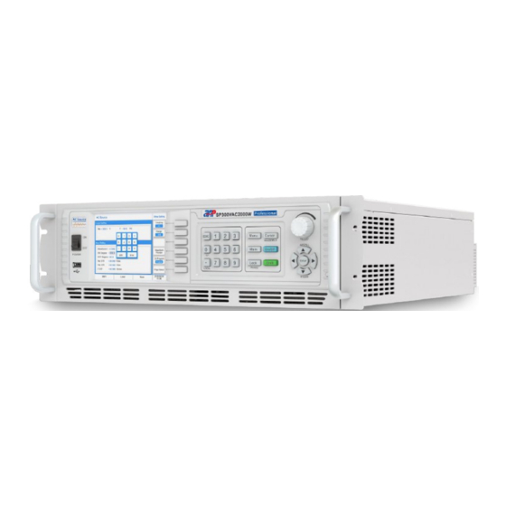
- Page 1 APM TECHNOLOGIES PROFESSIONAL INNOVATIVE BRANDING SERVICE en.apmtech.cn SP-300 Series Single-phase Programmable AC Power Supply User Manual...
-
Page 3: Table Of Contents
Contents Part NO. 18950-677-00 Contents Preface ............................4 Safety Notices ..........................5 1 About this Manual ........................6 1.1 Scope ..........................6 1.2 Targeted Audience ....................... 6 1.3 Use of this Manual and Legal Notices ................6 2 Unpacking ............................ 7 2.1 Packing List ........................... - Page 4 Contents 5 Menu Operation ........................18 5.1 Menu Introduction ......................18 5.1.1 Menu Structure ......................18 5.1.2 Introduction to Front Panel Operations ..............20 5.1.3 Key Operations and Touch Screen Operation ............20 5.2 Menu Operation ........................ 23 5.2.1 Setting Item ........................ 23 5.2.1.1 Output &...
- Page 5 Contents 7 Calibration ..........................93 7.1 Calibration Equipment Required ..................93 7.2 Calibration Procedure ....................... 93 7.2.1 Volt Setting & Measurement Calibration ..............94 7.2.2 Current Measurement Calibration ................95 7.2.2.1 I Range High, AC Low Current Coefficient ............96 7.2.2.2 I Range High, AC High Current Coefficient ............
-
Page 6: Preface
Preface Preface Dear Customer, Thank you for using this SP-300 Series Single-phase Programmable AC Power Supply, a product developed & manufactured by APM Technologies. We sincerely hope this product can meet your needs. The sections outlined in this user manual are suitable for the following product models:... -
Page 7: Safety Notices
Safety Notices Safety Notices Warning! This symbol highlights operations that have the potential to endanger users, operation proce- dures and instructions must be completely understood before use. Caution! Documentation must be consulted in all cases where this symbol is marked. Note This symbol highlights important instructions that need to be read before using the equipment. -
Page 8: About This Manual
Please check for updates at en.apmtech.cn and download the latest version of this manual and information. It is prohibited in any way to use all or part of the firmware or software developed by APM Technologies for other commercial purposes. It is prohibited to decompile, decrypt or otherwise damage the software developed by APM Technologies. -
Page 9: Unpacking
Unpacking Unpacking 2.1 Packing List Quantity Item Descriptions Remarks SP-300 Series Programmable AC Power Supply As ordered Rack Mount Brackets Standard Output Terminal Cover Box Standard Input Terminal Cover Box Standard Screws Fasten item B RS-232 Communication Cable Standard LAN communication Cable (568A-568B) -
Page 10: Checking For Shipping Damage
2.3 Product Damage or Failure Repair In the unlikely event of product failure, please promptly contact APM Technologies or its dealer and provide the serial number of the faulty AC power source, detailed fault information and pictures to help us identify the cause of the failure. -
Page 11: Product Features
Products Introduction The product includes comprehensive measurement functions and remote control and comm- unications. The units feature standard 19'' (48.3 cm) rack or bench-top mounting, many system based functions, local touch screen display and selector soft keys / knobs, remote analog and digital input control of its' operation. -
Page 12: Operation Instructions
Products Introduction 3.3 Operating Instructions This product is a precision instrument, please read this manual carefully before using. In order to ensure measurement accuracy it is recommended that this unit is calibrated annually by a calibration laboratory. To ensure the user safety, the input power cable, connector and accessories of this product should be inspected at least annually. -
Page 13: Product Storage
Products Introduction 3.6 Product Storage Please store this product in an area with a temperature between -40 °C and 85 °C and with a relative humidity of between 5% and 95% non-condensing. If the product is not going to be used for a long period, please keep it in the original carton or other similar packaging and store it in a cool &... -
Page 14: Starting Procedure
Plug in the AC power and turn on the power switch on the front panel, the programmable AC power source will execute a self-checking routine: The company name APM Technologies will appear on the front panel display: SELF CHECKING Model SP300VAC5000W Serial NO. -
Page 15: Panel Description
Panel Description Panel Description 4.1 Front Panel Description Front Panel of 2U Models Front Panel of 3U Models Front Panel of 4U Models PROFESSIONAL INNOVATIVE BRANDING SERVICE... - Page 16 Panel Description Input power switch. USB port is for data transfers and upgrading software. Color touch screen. Operation selection soft keys, to select displayed menu functions. Numeric and functional keys. Keys Manual Reference Name and the function [0]~[9] Numeric keys. Decimal point key.
-
Page 17: Rear Panel Description
Panel Description Confirm key and multifunctional keys. Keys Manual Reference Name and the function [Shift]+[ ] Recall the setup from internal memory. RECALL ( Shift + Store the settings in non-volatile memory. [Shift]+[ ] STORE ( Shift + Up/Left key. Down/Right key. - Page 18 Panel Description External Control Instruction EXT. V Pin 1 ON/OFF OUT OFF = Low (0~0.5V); OUT ON = High (4.5~5.5V) Pin 2 KEEP OFF KEEP OFF Disable = Low (0~0.5V); KEEP OFF Enable = High (4.5~5.5V) RESET RESET Active = Low (0~0.5V); RESET NOT Active = High (4.5~5.5V) Pin 3 CALL 1 Pin 4...
- Page 19 Panel Description Rear Panel of 3U Models Rear Panel of 4U Models AC/DC output terminals. Voltage sensor terminals. Cooling air outlets. Remote I/O & Parallel Multiphase Link card (Optional). Description Interface SYNC BNC connector input by external analog signal to control waveform amplitude. CAN-R Connect CAN-R in parallel mode.
-
Page 20: Menu Operation
Menu Operation Menu Operation 5.1 Menu Introduction 5.1.1 Menu Structure Main Page Setting Output Mode Store/Recall Parallel Series Menu Lock 3-Phase Setting Output & Measure Waveform Limitation More Setting Setting Viewer I Range Coupling Range Average Waveform Preview Is Delay Vdc(+) Zo Program Is Interval... - Page 21 Menu Operation Menu Config LCD Setting Calibration Other Remote Control Display Recall Default System Setting Date/Time Warning Log System Information Screen Calibration License External Control Firmware Update Screen Color Test Protection Output Mode PLD Testing Special Func Harmonics IEC Standard List Mode Synthesis IEC 4-11...
-
Page 22: Introduction To Front Panel Operations
Menu Operation Store/Recall Save Output Save System Recall Output Recall System 5.1.2 Introduction to Front Panel Operations Note The Default setting values will be used if setting values are not saved before restarting. 1. Front panel key is used for turning the power source On or Off. On/Off 2. - Page 23 Menu Operation 3. Once this value field is highlighted press the rotary knob, an underline cursor will be displayed under the value as show as below(left). Pressing the front panel knob again will change the cursor position, rotating the front panel knob or pressing the numeric keys will adjust the particular digits value.
- Page 24 Menu Operation Menu setting Option one (using front panel keys) 1. Press the ‘Coupling’ soft key to display the output coupling options. 2. Press the [ ] / [ ] key to highlight ‘AC+DC’ option, then press the [Enter] key to confirm. 3.
-
Page 25: Menu Operation
Menu Operation 5.2 Menu Operation We will explain menu operation using the front panel keys as touch screen operation is self- explanatory. 5.2.1 Setting Item The following Soft Keys are available in the Setting screen to access these setup screens. Output &... - Page 26 Menu Operation 1. Output Coupling This menu is for setting the output mode of the AC source including ‘AC’, ‘DC’, and ‘AC+DC’ modes. For example, to set ‘Coupling’ as ‘AC+DC’. 1. In the ‘More Settings’ screen, press the ‘Coupling’ soft key to display the drop down list. 2.
- Page 27 Menu Operation Note When changing the range setting, turn off the AC source output first. The Range setting can not be changed if the output is on. There is a temporary OFF (approx. 300ms) to the AC source during the switchover of range. Range setting will be always display on the lower-left conner of the display.
- Page 28 Menu Operation 4. Degree Setting This item is for editing the start and end angles of the AC output when the output is turned on and turned off. The ‘ON Degree’ (start angle) range is 0~359.9 degrees. The ‘OFF Degree’ (end angle) range is 0~359.9 degrees and ‘Disable’.
- Page 29 Menu Operation Note If the user programs a slew rate setting, the ON Degree (start phase angle) of an AC output waveform may not be directly visible. It can be inferred however from the waveform cycle and frequency setting. 6. Waveform Preview This item is for preview the currently selected waveform.
-
Page 30: Measurement Setting
Menu Operation Warning! The upper limit for Programmable output impedance is 1.0 Ohm / 1.0 mH. If L is more than 0.5 mH and the output voltage is low (e.g. less than 100Vac), any large load current may cause an unstable output voltage. It is important that the user adjusts the L value slowly while monitoring the output voltage and listening for any unusual sounds coming from the power source. - Page 31 Menu Operation Glossary of Terms V, the RMS of total output voltage (Vac and Vdc), measured in volts. Vac, AC output voltage, measured in volts. Vdc, DC output voltage, measured in volts. Vpk, Peak-peak output voltage, measured in volts. I, the RMS of total output current (Iac and Idc), measured in amps. Iac, AC output current, measured in amps.
- Page 32 Menu Operation The following four Soft keys are available in the Measurement Settings screen: I Range Average Is Delay Is Interval 1. I Range The I Range soft key allows selection of the current measurement range. Available settings are High, Middle, Low, Auto and mA. For example, to set I Range as Low.
- Page 33 Menu Operation 2. I Average The Average soft key changes the number of times a reading is averaged before the corres- ponding measurement parameter display is updated. Available average values are 1, 2, 4, 8, 16 and 32. For example, to set Average time as 2. 1.
-
Page 34: Waveform Viewer Setting
Menu Operation 5.2.1.3 Waveform Viewer Setting This item is for viewing the currently selected waveform. In the ‘Settings’ screen, press the ‘Waveform Preview’ soft key to display the currently selected waveform. Press the [ESC] key to turn off the viewer. 5.2.1.4 Limitation Setting The limitation soft key displays the user limit setting screen. -
Page 35: Menu Setting
Menu Operation Note User limits are independent of the selected voltage range so an upper Vac limit setting higher than 150V will have no effect while on the 150V AC voltage range as the voltage range limit supersedes the user limit. 5.2.2 Menu Setting The following soft keys are available in the Menu screen to access these settings:... - Page 36 Menu Operation 1. In the ‘Remote Control’ menu, press the ‘RS 232’ soft key to change RS 232 interface settings. 2. Move the cursor to highlight ‘Baud Rate =’ field then press the [Enter] key to confirm. 3. Rotate the front panel knob to highlight ‘19200’, and then press the [Enter] key to confirm. 1.2 RS485 Available Baud Rate are: 9600, 19200, 38400, 57600, 115200.
- Page 37 Menu Operation 1.3 GPIB ‘GPIB Addr’: 1~30. For example, to set ‘GPIB Addr’ as 5. 1. In the ‘Remote Control’ menu, press the ‘GPIB’ soft key to change GPIB interface settings. 2. Move the cursor to highlight ‘GPIB Addr =’ field, then press [5] and [Enter] keys to confirm. 1.4 Ethernet Settings Parameter ranges are: ETH Setting: Auto, Manual.
- Page 38 Menu Operation 2. System Settings This item is for setting the basic operation of the system including ‘Buzzer’, ‘P/O State’ and ‘O/P Relay’. 2.1 Buzzer The buzzer of the AC source beeps when the user presses the keypad on the front panel, or press the PRG knob.
- Page 39 Menu Operation 2.2 P/O State The AC source allows the user to store the output settings as the default settings before pow- ering the unit off. If ‘OFF’ is selected the unit will NOT store any settings when powered off and initialize with factory default at power on.
- Page 40 Menu Operation 2.3 O/P Relay There is an isolation relay to connect or disconnect the load from the output of the power source. When ‘O/P Relay’ is ‘ON’, the relay always remains closed, regardless of the programmed output state, even if the output state is OFF. When the output relay is set to ‘OFF’, the output relay will close when the output state is ON and open when the output state is OFF.
- Page 41 Menu Operation 4. External Control The AC source allows the user to make use of a controlling signal from external devices to determine its output. When ‘Extern Control’ is ‘ON’, it will enable TTL or ANALOG control input signals, please refer to Section 4.2 “Real Panel Description” on page 18 for detailed information. When ‘Analog Volt I/P’...
- Page 42 Menu Operation Warning! If Peak level of the external signal exceeds 10V or the frequency exceeds 1200Hz, damage to the power source may will result. 5. Protection This subsection is relevant to user-programmable protection, not internal hardware protection. ‘OPP’ (over power protection): setting range is from 0 through 1.02 times of rated power. ‘OCP’...
-
Page 43: Lcd Setting
Menu Operation Note If the output power is 1~1.1 times of the OPP setting, the output will shut down in about 10s. If the output power greater than 1.1 times of the OPP setting, the output will shut down in about 1.2s. If the output current greater than 1.05 times of the OCP setting, the output will shut down in about 500ms. - Page 44 Menu Operation 2. Date/Time The power source has a real-time date and time clock. It is set at the factory at the time of shipment but will have to be adjusted for local date and time zone. 1. In the ‘LCD setting’ screen, press the soft key to the right of ‘Date/Time’. 2.
-
Page 45: Calibration
Menu Operation 5.2.2.3 Calibration For calibration information, refer to Chapter 7 Calibration. 5.2.2.4 Other Setting The Other setting screen contains miscellaneous system settings. The following items can be configured from this screen. Recall Default Warning Log License Firmware Update 1. Recall Default The Recall Default screen can be used to recall original factory (default) settings. -
Page 46: Output Mode
Menu Operation 3. License Displays license information. 4. Firmware Update This screen is used to perform a firmware update. 5.2.3 Output Mode The following items can be configured from this screen. PLD Testing Harmonics IEC Standard Special Func Test Mode 5.2.3.1 PLD Testing Power Line Distortion testing allows testing of a unit under test for immunity against... - Page 47 Menu Operation The AC source provides powerful functions to simulate a variety of power line disturbance situations. From the ‘Output Mode’ screen press the soft key to the right of ‘PLD testing’ to display the three PLD testing screen. 1. List Mode This mode includes 50 generically named files.
- Page 48 Menu Operation 5. Press the [ESC] key to return to the previous screen, press the ‘Trigger’ soft key to load the settings. 6. Press the ‘Trigger’ soft key to execute the list file, and the ‘Trigger’ will change to ‘Stop’. Note If you execute the list file with the AC Source ‘ON’, it will return to the output to the settings of the main screen after the list file execution has completed, or it will turn ‘OFF’.
- Page 49 Menu Operation Each list sequence file has total 9 steps, each step is a complete list file. During execution, the running status of the list files is shown in the top part of the display, and the running status of the sequence file is shown in the bottom part.
- Page 50 Menu Operation 3. Press the [ESC] key to return to the previous screen then press the ‘Trigger’ soft key to load the settings. 4. Press the ‘Trigger’ soft key to execute the file, and the ‘Trigger’ will change to ‘Stop’. During execution, the remaining period time is shown in the top part of the display.
-
Page 51: Harmonics
Menu Operation Power Sweep, sweep function. Save, to save setting to assigned memory room for quickly recall at any time. Do not save the setting, after power off the unit, current file will lose. 3. Press the [ESC] key to return to the previous screen, then press the ‘Trigger’ soft key to load the settings. - Page 52 Menu Operation 1. Synthesis The waveform synthesis screen is used to create waveforms made up of a series of harmonic frequencies, amplitudes and phase shifts. Up to 40 order harmonics of 50Hz to 60Hz can be specified. 1. In the ‘Harmonics’ menu press the ‘Synthesis’ soft key. 2.
- Page 53 Menu Operation 3. Press the [ESC] key to return to the previous screen then press the ‘Trigger’ soft key to load the settings. 4. Press the ‘Trigger’ soft key to execute the file, and the ‘Trigger’ soft key will be changed to ‘Stop’.
- Page 54 Menu Operation 2. Inter-harmonics Inter-harmonics allow the user to insert a frequency component sweep at the output at a fre- quency that is not harmonically related to the fundamental frequency. This function is useful for performing immunity tests. 1. Press the ‘Inter-harmonics’ soft key to display the Inter-Harmonics screens shown below. 2.
- Page 55 Menu Operation 3. Harmonic Measure The harmonics measurement function measures total harmonic distortion (THD), DC voltage and current and fundamental voltage and current for output setting of 50Hz or 60Hz. Thus, this function is useful for commercial and industrial development and test applications. 1.
- Page 56 Menu Operation Compose = Value or Percent. Waveform Preview: previews the graphical representation of the harmonic measurements. 4. Press the ‘Trigger’ soft key to execute the file, and the ‘Trigger’ will change to ‘Stop’. 4. User The User function contains 6 sets of user defined harmonic waveforms, User NO. 0 through User NO.
- Page 57 Menu Operation Last Page/Next Page Waveform Preview: previews the graphical representation of the waveform. Save: to save User waveform settings to the assigned memory location for quickly recalling at a later time. If you do not save the current User file, it will be lost after the unit is turned off. The user can recall the user-defined waveform in Output &...
-
Page 58: Iec Standard
Menu Operation 5.2.3.3 IEC Standard The IEC 61000-4 test function support immunity testing to the following four IEC 61000-4 standards: IEC 4-11 IEC 4-13 IEC 4-14 IEC 4-28 1. IEC 4-11 This menu enables users to perform the pre-compliance tests Voltage Dips and Voltage Varia- tions against IEC 61000-4-11. - Page 59 Menu Operation 6. Press the numeric keys and [Enter] key to set Count, the available range of which is 0~65535 where 0 means infinite loop. 7. Move the cursor to highlight ‘Frequency =’ field, then press the [Enter] key to switch between 50 and 60.
- Page 60 Menu Operation 8. Press the ‘Diagram’ soft key to preview the outline of the test waveform. 9. Press the ‘Save’ soft key to store the dips and short Cycle Interval settings in memory. 10. Press the [ESC] key to return to the previous screen then press the ‘Load’ soft key to load the settings.
- Page 61 Menu Operation 3. Press the ‘Edit’ soft key. 4. Move the cursor to highlight ‘Operation =’ field, then press the [Enter] key to switch between Standard and User Def. If User Def is selected adjust the voltage variation parameters below as desired using the cursor and front panel knob.
- Page 62 Menu Operation 5. Press the ‘Diagram’ soft key to preview the envelope of the test waveform. 6. Press the ‘Save’ soft key to store the settings in non-volatile memory. 7. Press the [ESC] key to return to the previous screen then press the ‘Load’ soft key to load the settings.
- Page 63 Menu Operation 3. Press the ‘Edit’ soft key. 4. Move the cursor to highlight ‘Test Level =’ field, then press the [Enter] key to display the drop down list. 5. Rotate the front panel knob to highlight ‘Class 1’ and then press the [Enter] key to confirm. Adjust the parameters below if it is desired for them to be different from the default IEC 4-13 values.
- Page 64 Menu Operation 6. Press the ‘Waveform Preview’ soft key to see a visual representation of the test waveform. Press again to clear the preview. 7. Press the ‘Save’ soft key to store the test setting in non-volatile memory. 8. Press the [ESC] key to return to the previous screen then press the ‘Trigger’ soft key to load the settings.
- Page 65 Menu Operation 3. Press the ‘Edit’ soft key. 4. Move the cursor to highlight ‘Test Level =’ field, then press the [Enter] key to display the drop down list. 5. Rotate the front panel knob to highlight ‘Class 1’ then press the [Enter] key to confirm. Unom = nominal test voltage.
- Page 66 Menu Operation The test time now run until completed. Total test time is determined by the Test Time setting. The test time count down in seconds is visible in the upper part of the IEC 4-13 screen. At the completion of the test, the ‘Stop’ soft key will revert to ‘Trigger’. To abort a test in pro- gress, press the ‘Stop’...
- Page 67 Menu Operation 6. Move the cursor to highlight ‘Level =’ field, then press the [Enter] key to display the drop down List. 7. Rotate the front panel knob to highlight ‘Class 2’ and press the [Enter] key to confirm. 8. Press the ‘Save’ soft key to store the test setting in non-volatile memory. 9.
- Page 68 Menu Operation Inter-harmonics Setting 1. In the ‘IEC standards’ screen press the ‘IEC 4-13’ soft key. 2. Press the ‘Inter-harmonics’ soft key to display the Inter-harmonics test screen. 3. Press the ‘Edit’ soft key to set the required test selections for this test. 4.
- Page 69 Menu Operation Unom, Nominal test voltage, fixed to 230V in standard modes. Frequency, 50Hz or 60Hz in standard modes. Test Levels in % of Unom for Inter-Harmonics ranges: Default test levels, % Unom, for 50Hz mains. 0.33*f1 to 2*f1, 16~100 Hz, 2.5%; 2*f1 to 10*f1, 100~500 Hz, 5.0%;...
- Page 70 Menu Operation Sweep in Frequency Setting 1. In the ‘IEC standards’ screen press the ‘IEC 4-13’ soft key. 2. Press the ‘Sweep in Frequency’ soft key to display the test screen. 3. Press the ‘Edit’ soft key to set the required test selections for this test. 4.
- Page 71 Menu Operation 6. Press the ‘Save’ soft key to store the settings in non-volatile memory. 7. Press the [ESC] key to return to the previous screen, press the ‘Trigger’ soft key to load the settings. 8. The resonance frequency will be displayed on the screen after the test has finished. The test time now run until completed.
- Page 72 Menu Operation Unom, Nominal test voltage, fixed to 230V in standard modes. Frequency, 50Hz or 60Hz in standard modes. Test Levels in % of Unom for Inter-Harmonics ranges: Default test levels, % Unom, for 50Hz mains. 0.33*f1 to 2*f1, 16~100 Hz, 3.0%; 2*f1 to 10*f1, 100~500 Hz, 9.0%;...
- Page 73 Menu Operation 3. IEC 4-14 This menu allows users to perform the pre-compliance test Voltage Fluctuation Immunity according to IEC 61000-4-14. The test item parameters also can be user-defined. 1. In the ‘IEC standards’ screen press the ‘IEC 4-14’ soft key. 2.
- Page 74 Menu Operation 5. Press the ‘Diagram’ soft key to see a visual representation of the test waveform. Press again to clear the preview. 6. Press the ‘Save’ soft key to store the test setting in non-volatile memory. 7. Press the [ESC] key to return to the previous screen then press the ‘Trigger’ soft key to load the settings.
- Page 75 Menu Operation 3. Move the cursor to highlight the ‘Operation=’ field and press the [Enter] key to switch between Standard and User Defined. 4. Move the cursor to highlight the ‘Test Level=’ field then press the [Enter] key to display the drop down list, rotate the front panel knob to highlight ‘Level 2’...
-
Page 76: Special Func
Menu Operation 5. Press the ‘Diagram’ soft key to see a visual representation of the test waveform. Press again to clear the preview. 6. Press the ‘Save’ soft key to store the fl+delta test setting in non-volatile memory. fl+delta 7. Press the [ESC] key to return to the previous screen then press the ‘Trigger’ soft key to load the settings. - Page 77 Menu Operation 1. Transient Transient test simulates the effects of high speed voltage spikes and sags on a unit under test. 1. In the ‘Special Func’ screen press the ‘Transient’ soft key to select the Transient test mode. 2. Press the ‘Edit’ soft key to set the parameters. Trans-Start, to set the time of the first transient.
- Page 78 Menu Operation 2. Triac Dimmer The leading or lagging edge of the voltage waveform can by blanked with a phase angle set by the Triac Dimmer function to regulate the active power, thus adjusting the lighting intensity in the case of a luminary load. 1.
- Page 79 Menu Operation Edge, to set the dimmer of leading edge or trailing edge mode. Degree, phase angle of the blanking period. 3. Press the ‘Save’ soft key to save the settings to non-volatile memory. 4. Press the [ESC] key to return to the previous screen then press the ‘Trigger’ key to load the settings.
- Page 80 Menu Operation 1. In the ‘Output Mode’ screen press the ‘Test Mode’ soft key to enter limit test mode. Low Limit: lower limit of parameter settings. High Limit: upper limit of parameter settings. Switch: selectable to Disable or Enable. Delay Time: the delay time to enter into test mode when output is turned ON. Test Time: duration of measurement and limit compare period.
-
Page 81: Parallel/Series/3-Phase
Menu Operation 5.2.4 Parallel/Series/3-Phase For details on Master-slave mode operation, please refer to Chapter 6. 5.2.5 Store/Recall The memory resources are access using the following four soft keys: Save Output Save System Recall Output Recall System In the ‘Main Page’ screen press the ‘Save/Recall’ soft key to enter the save/recall sub-menu. 1. - Page 82 Menu Operation 2. Save System/Recall System This AC source provides 5 non-volatile memory groups to save instrument system settings for recalling at a later time. 1. Press the ‘Store/Recall’ to save a system setting. 2. Move the cursor to the Group field located in the middle of the screen. Use [0]~[9] keys to select a group number from 1 through 9 and press [Enter] key to save the system settings to this group register.
-
Page 83: Lock
Menu Operation 5.2.6 Lock The front panel keys and touch screen operation can be locked to prevent unwanted changes to output settings and the AC source configuration. To lock the front panel keys and touch screen from the ‘Main Page’ screen press the soft key to the right of ‘Lock’. A lock sign will be displayed on the bottom right of the screen. -
Page 84: Master-Slave Mode Operation
Master-slave Mode Operation Master-slave Mode Operation SP-300 Series Programmable AC Power Supply can be connected in parallel/series and 3-phase system to increase the output power. Note DO NOT connect units in both series and parallel at the same time. DO NOT connect different models in parallel or series mode. -
Page 85: Setting The Unit As Master
Master-slave Mode Operation 3. Move the cursor to highlight ‘Slaver’ option and press the [Enter] key to confirm. 4. Move the cursor to the command line ‘Slaver Type =’ and select the slaver number, then press the [Enter] key to confirm. 5. - Page 86 Master-slave Mode Operation 3. Move the cursor to highlight ‘Master’ option and press the [Enter] key to confirm. 4. Move the cursor to highlight the ‘Master Type =’ field and press the [Enter] key to confirm. 5. Move the cursor to highlight the right option and press the [Enter] key to confirm. 6.
-
Page 87: Parallel System
Master-slave Mode Operation 6.2.1 Parallel System Set ‘Master Type’ of the master unit as ‘Parallel’, then press the [Main] key switch to main menu. Parallel connection 1 2 3 Output connection Termination resistor CAN-R, flip Dip Switch 1 of the Master unit to ON position (down) System Bus Communication Cable PROFESSIONAL INNOVATIVE BRANDING SERVICE... -
Page 88: Series System
Master-slave Mode Operation 6.2.2 Series System Set ‘Master Type’ of the master unit as ‘Series’, then press the [Main] key to return to the main page. Series connection 1 2 3 Output connection Termination resistor CAN-R, flip Dip Switch 1 of the Master unit to ON position (down) System Bus Communication Cable PROFESSIONAL INNOVATIVE BRANDING SERVICE... -
Page 89: 3-Phase System
Master-slave Mode Operation 6.2.3 3-Phase System The output of the 3-Phase system can be connected for three-phase four-wire (Y type) system or three-phase five-wire (△ type) system. Note In this 3-phase system, the Master unit is always phase A, Slave1 is always phase B and Slave2 is always phase C. - Page 90 Master-slave Mode Operation Main page PROFESSIONAL INNOVATIVE BRANDING SERVICE...
- Page 91 Master-slave Mode Operation Three-phase five-wire (Y type) connection, the output voltage range is 0~300V. 1 2 3 Output connection Termination resistor CAN-R, flip Dip Switch 1 of the Master unit to ON position (down) System Bus Communication Cable Only support three-phase five-wire input connection PROFESSIONAL INNOVATIVE BRANDING SERVICE...
- Page 92 Master-slave Mode Operation Three-phase four-wire (△ type) connection, the output voltage range is 0~519V. 1 2 3 Output connection Termination resistor CAN-R, flip Dip Switch 1 of the Master unit to ON position System Bus Communication Cable Only support three-phase five-wire input connection PROFESSIONAL INNOVATIVE BRANDING SERVICE...
-
Page 93: Error List Of Master-Slave Mode
Master-slave Mode Operation 6.2.4 Error List of Master-slave Mode Alarm Code Information Instruction 0x0401 Mode Not Match Mode not match 0x0402 Model Not Match Model not match 0x0404 No Phase B No Phase B 0x0408 No Phase C No Phase C 0x0410 Master Conflict More than one mater units in the system... - Page 94 Master-slave Mode Operation Single Unit Parallel System Series System 3-Phase System Menu Sub-menu Waveform Viewer Yes, slavers in sync with the master unit Limitation Remote Control System Setting Config System Information External Control Not Support Protection Yes, slavers in sync with the master unit LCD Setting Not Supported Not Supported...
-
Page 95: Calibration
Calibration Calibration The AC source allows the user to calibrate the unit through the menu including Voltage Setting and Voltage and Current Measurement. The user can selectively calibrate these items, though it is best if a calibration lab performs the calibration. 7.1 Calibration Equipment Required 1. -
Page 96: Volt Setting & Measurement Calibration
Calibration 7.2.1 Volt Setting & Measurement Calibration This item is for calibrating the voltage setting and measurement. Make sure to disconnect the Resistive load before starting calibration. 1. Once the password has been entered press the soft key to the right of ‘Volt Setting & Measure’. 2. -
Page 97: Current Measurement Calibration
Calibration 4. Wait 2 seconds then press the ‘Continue’ key. 5. Highlight the value field and enter the DVM AC voltage reading then press the ‘Continue’ soft key for the next step. Follow the on-screen prompts to complete calibration the 150V AC range. Both AC & DC output and AC &... -
Page 98: I Range High, Ac Low Current Coefficient
Calibration Once the password has been entered press the soft key to the right of ‘Current Measure’. 7.2.2.1 I Range High, AC Low Current Coefficient 1. Make sure the load in connected (switch is closed) and adjust the load setting for a current of 1 Aac +/- 10%. -
Page 99: I Range High, Dc Low Current Coefficient
Calibration 1. Adjust the load setting for a current of 24 Aac +/- 10%. 2. Highlight the Measured I field value, then enter the current reading from the DAM. When done, press the [Continue] key to the next calibration coefficient. 7.2.2.3 I Range High, DC Low Current Coefficient 1. -
Page 100: Saving Calibration Coefficient
Calibration When done, press the ‘Continue’ key to the next calibration coefficient. Continue to follow the on-screen prompts till the calibration process for Middle and Low current measurement calibration is complete. Note It is possible to skip any coefficient by press the ‘Skip’ soft key if calibration is deemed but it is better to follow the prompt messages provided on the display, step by step. -
Page 101: Installation
Installation Installation 8.1 Product Dimensions 423.0 423.0 30.0 30.0 483.0 483.0 Dimensions of 2U Models Dimensions of 3U Models 423.0 30.0 483.0 Note: refer to Appendix A to get the detailed information of the dimensions of the power sources. Dimensions of 4U Models PROFESSIONAL INNOVATIVE BRANDING SERVICE... -
Page 102: Installing Rack Mount Handles
Installation 8.2 Installing Rack Mount Handles Caution! The handles are used to fix the unit in the rack instead of carrying the unit. Install the rack mount handles provided in the ship kit on the power source before mounting the unit in an instrument rack. Refer to the illustration on the right for correct assembly. - Page 103 Installation This series AC source provides optional interface cards. The interface slot is located on the rear panel, making it easy for the user to plug a new interface. Refer to the illustration on the right for correct assembly. Optional interface cards for this series AC source are as below.
-
Page 104: Shelf Mounting Diagram Of Ac Source
Installation 8.4 Shelf Mounting Diagram of AC Source 20mm SP-300 Series Programmable AC Power Supply can be installed in a standard 19-inch equipment rack, to make it easy to integrate it into yourtest system. Due to the weight of the unit a shelf or rear support is needed in addition to the supplied front panel brackets. - Page 105 Installation Note Instruction not to position the equipment so that it is difficult to operate the disconnecting device. Approved flexible cords with double insulation, suitable size, min. 60 deg C as in the follo- wing table must be used as AC input. For SP300VAC5000W, input current limit within 30A.
-
Page 106: Output Connection
Installation 8.6 Output Connection Warning! Be sure to disconnection from AC before access to AC output and AC input compartment. Approved flexible cords with double insulation, suitable size, min. 60 deg C as in the follo- wing table must be used as power output. Use certified type double insulated wire or cord of 18~25 mm in diameter. -
Page 107: Remote Compensation
Installation 8.7 Remote Compensation Remote sensing allows the power supply to automatically compensate for up to 5V voltage drop in the wires connected to the load. 1. For local sensing please refer to figure a. This method does not compensate for voltage drop on the load wires, therefore it is recommended only for low load currents, short connections to the load or where the load regulation is less critical. -
Page 108: Troubleshooting
Troubleshooting Troubleshooting Problem Causes Solutions The screen shows the Primary temperature is too high. Ask your agent for help. message C001 PRI_OTP. The screen shows the Input over current. Ask your agent for help. message C002 PRI_OCP. Turn off the output and check the AC Input over voltage. - Page 109 Troubleshooting Problem Causes Solutions The screen shows the Output over power. Adjust the OPP setting. message C011 OUTPUT OPP. The screen shows the Secondary temperature is too high. Ask your agent for help. message C012 SEC OTP The screen shows the Ask your agent for help.
-
Page 110: Recycling And Disposal
Contact Us If you have any questions about the SP-300 Series Programmable AC Power Supply, please contact us. We will be happy to answer any of your questions. Below are our contact details:... -
Page 111: Appendix A Specifications
Appendix A Specifications Appendix A Specifications S P300VAC600W S P300VAC1000W S P300VAC1500W Model Input Voltage 90~265VAC 90~265VAC 100~265VAC Frequency 47~63Hz Phase 1 Phase, 2Wire+Groud Max. Current ≥ 0.91 Active PFC ≥ 0.95 Active PFC ≥ 0.97 Active PFC Power Factor at 220VAC Input, Full Load >... - Page 112 Appendix A Specifications Model S P300VA C600W S P300VA C1000W S P300VA C1500W 0~1500W Range 0~600W 0~1000W Power 0.1W Resolution Accuracy 0.4% of setting + 1.0% F.S. at PF>0.2, Voltage>5V Range 0~612VA 0~1020VA 0~1530VA Power Apparent Resolution 0.1VA (VA) Accuracy Voltage*Irms, Calculated value Power Range...
- Page 113 Appendix A Specifications Model S P300VAC2000W S P300VAC3000W S P300VAC4000W S P300VAC5000W Input Voltage 190~265VA C Frequency 47~63Hz Phase 1 Phase, 2Wire+Groud Max. Current Power Factor at 220VAC Input, Full Load ≥ 0.99, ActiveP F C ≥ 0.98, ActiveP F C ≥...
- Page 114 Appendix A Specifications Model S P300VAC2000W S P300VAC3000W S P300VAC5000W S P300VAC4000W Range 0~2040W 0~3060W 0~4080W 0~5100W Power Resolution 0.1W Accuracy 0.4% of setting + 1.0% F.S. at PF>0.2, Voltage>5V Range Power 0~2040VA 0~3060VA 0~4080VA 0~5100VA Apparent Resolution 0.1VA (VA) Accuracy Voltage*Irms, Calculated value Power...
-
Page 115: Appendix B Fixed Waveforms
Appendix B Fixed Waveform Appendix B Fixed Waveform FIXED, NO.=0 Harmonic θ 15.8 2.16 FIXED, NO.=1 Harmonic θ 1.44 1.47 1.95 FIXED, NO.=2 Harmonic θ 1.96 1.37 1.98 1.42 PROFESSIONAL INNOVATIVE BRANDING SERVICE... - Page 116 Appendix B Fixed Waveform FIXED, NO.=3 Harmonic θ 2.45 1.88 2.46 1.95 1.09 1.52 1.09 FIXED, NO.=4 Harmonic θ 1.00 2.75 1.35 2.25 1.45 FIXED, NO.=5 Harmonic θ 4.17 1.02 2.92 PROFESSIONAL INNOVATIVE BRANDING SERVICE...
- Page 117 Appendix B Fixed Waveform FIXED, NO.=6 Harmonic θ 2.17 5.59 2.79 4.58 2.92 1.35 0.99 FIXED, NO.=7 Harmonic θ 4.86 1.58 2.64 1.37 1.95 1.06 FIXED, NO.=8 Harmonic θ Harmonic θ 7.27 1.59 2.39 1.04 4.01 1.19 2.07 1.03 1.03 2.94 PROFESSIONAL INNOVATIVE BRANDING SERVICE...
- Page 118 Appendix B Fixed Waveform FIXED, NO.=9 Harmonic Harmonic θ θ 9.78 3.92 3.19 2.13 5.37 1.34 1.17 1.39 2.76 1.59 1.37 1.36 FIXED, NO.=10 Harmonic θ 17.72 FIXED, NO.=11 Harmonic θ 21.21 PROFESSIONAL INNOVATIVE BRANDING SERVICE...
- Page 119 Appendix B Fixed Waveform FIXED, NO.=12 Harmonic θ 24.48 FIXED, NO.=13 Harmonic θ 2.19 9.83 15.76 FIXED, NO.=14 Harmonic θ 1.04 7.86 1.14 PROFESSIONAL INNOVATIVE BRANDING SERVICE...
- Page 120 Appendix B Fixed Waveform FIXED, NO.=15 Harmonic θ 2.42 3.91 FIXED, NO.=16 Harmonic θ 11.08 4.05 2.03 1.27 FIXED, NO.=17 Harmonic θ 7.16 3.46 PROFESSIONAL INNOVATIVE BRANDING SERVICE...
- Page 121 Pappendix B Fixed Waveform FIXED, NO.=18 Harmonic θ 8.07 3.55 0.96 0.92 FIXED, NO.=19 Harmonic θ 9.38 3.44 1.12 FIXED, NO.=20 Harmonic θ 2.06 1.77 1.62 1.23 0.91 0.54 0.51 0.53 PROFESSIONAL INNOVATIVE BRANDING SERVICE...
- Page 122 Appendix B Fixed Waveform FIXED, NO.=21 Harmonic Harmonic θ θ 3.08 0.62 2.72 0.73 2.43 0.77 1.97 0.69 1.41 0.56 0.86 FIXED, NO.=22 Harmonic Harmonic θ θ 0.13 0.55 4.28 0.46 3.77 0.83 3.27 0.97 2.57 1.04 1.93 0.75 1.22 FIXED, NO.=23 Harmonic θ...
- Page 123 Appendix B Fixed Waveform FIXED, NO.=24 Harmonic Harmonic θ θ 7.35 0.74 1.35 5.74 1.64 4.57 1.73 3.41 1.56 2.16 1.24 1.04 FIXED, NO.=25 Harmonic Harmonic θ θ 3.41 3.88 2.55 3.56 9.22 7.68 2.34 2.21 FIXED, NO.=26 Harmonic θ 1.24 4.91 2.21...
- Page 124 Appendix B Fixed Waveform FIXED, NO.=27 Harmonic Harmonic θ θ 33.39 20.01 3.49 13.76 2.91 10.7 2.45 8.39 1.94 7.06 1.95 5.85 1.91 4.86 1.89 4.86 1.83 4.52 FIXED, NO.=28 Harmonic Harmonic θ θ 33.39 3.93 20.01 0.89 13.75 0.92 10.71 0.94 8.37...
-
Page 125: Appendix C Warranty
Thank you for purchasing the Programmable AC Power Source of APM Technologies (referred to hereafter as “APM”). In order for you to use our products properly, APM provides you with the standard warranty service as stipulated below. Please read the following instructions carefully. - Page 126 5. Accessories included with each product are not in the product warranty scope. 6. Defects or damages caused by or resulting from inadequate or improper repairs carried out by any person, entity or service facility which is not authorized by APM to perform warranty services on its behalf.
- Page 127 If in any situation APM puts forward or expresses the warranty commitments con- flicting with the above clauses, it should be subject to the later one. 2. In order to uphold your warranty rights, please call or mail APM Customer Service to register your product and to put warranty coverage in force.
- Page 128 Schedule Product Information Company Name Contact Person Distributor Phone Code Address User’s Information Name Phone Code Address E-mail Product Malfunction Information Model Serial No. Warranty Period Signature Malfunction Description & Solutions Date of Malfunction Please stick the product Serial number here.
- Page 132 Add: # 7, Link Information Industry Park, Shuilianshan Road,Nancheng, Dongguan, Guangdong, China Tel: +86 769 2202 8588 E-mail: overseas@apmtech.cn Fax: +86 769 2202 6771 Web: en.apmtech.cn...
Need help?
Do you have a question about the SP-300 Series and is the answer not in the manual?
Questions and answers