Table of Contents
Advertisement
Quick Links
Advertisement
Table of Contents

Subscribe to Our Youtube Channel
Related Manuals for Savch SEC-M500


Summary of Contents for Savch SEC-M500
- Page 1 SEC-M500 Elevator Controller User manual User Manual...
- Page 2 520005002800 Vision No. V1.0 Filing time 2018-04-08 SAVCH electric provide a full range of technical support for our customers. All users could contact with the nearest SAVCH office or service center, also could contact with our headquarters directly. SAVCH Electric reserves the copyrights and all rights,...
-
Page 3: Table Of Contents
1.2 Notes for Operation Environment ..................3 2. Function introduction ........................4 3. Product introduction ........................7 3.1 Main control panel SEC-M500 ..................... 7 3.2 Hall calling display board SEC-E01 ................... 13 3.3 Car board SEC-C01 ......................15 4. Operation interface ........................19 4.1 Brief introduction ........................ -
Page 4: Preface
Provided problems occur and solution is not provided in this instruction manual, contact your SAVCH ELECTRIC representative or contact with our company directly. Our professional technicians will serve for you actively. And please continue to adopt products of SAVCH, give valuable opinion and advice. -
Page 5: Safety Instructions
1. SAFETY INSTRUCTIONS 1.1 Safety Precautions Use note DANGER This product can be used for passenger elevators, cargo lift and other vertical elevator. This product is manufactured under strict quality control conditions. If the product is used in the equipment which is possible to be damaged by our product cause of fault, please set up the safety device in case of any accident. -
Page 6: Notes For Operation Environment
1.2 Notes for Operation Environment Direct sunlight Corrosive gas or fluids Salt Salt or saline Rain, moisture Iron chips and dust Below 10 degrees Celsius Force cool Force Force Force Force Force Extreme high ambient Large impelling Extreme low temperatures temperatures (Above 40 ) Electromagnetic waves Locations of inflammable... -
Page 7: Function Introduction
2. FUNCTION INTRODUCTION Item Function Description Remark Common function Floor service The system supports the floor service not more than 32 floors. Power supply When there is no operation and the time reach to the power management management set, turn off the car lights and fans to save energy. When the function is opened, during the setted time, the bell is Bell time switch ready. - Page 8 Item Function Description Remark Common function Time of automatic Set the time of automatically close door according to type of closing door elevator, inside calling, hall calling. If the light curtain block cause closing or opening door normally Nudging exceeding 10 times and the nudging is open, the light curtain block will be ignored and then nudging.
- Page 9 Item Function Description Remark Inspection and debugging When elevator is under condition of running and is at maintenance Maintenance state, closing maintenance up/maintenance down makes elevator operation running at the maintenance speed. When open, the elevator stops. Open door operation, please refer to related parameter. Automatic running according to the running time, running time Automatic operation interval, car calling generate at random to run elevator,...
-
Page 10: Product Introduction
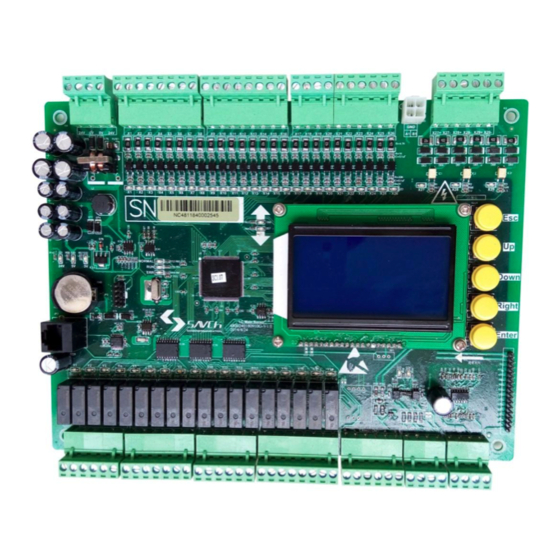
3. PRODUCT INTRODUCTION 3.1 Main control panel SEC-M500 3.1.1 External dimension Figure 3-1 outlook of main control panel SEC-M500 Figure 3-2 installation dimension of main control panel SEC-M500... - Page 11 3.1.2 Port instruction Port type of SEC-M500: power supply port, common optical coupling input, high speed optical coupling input. AC110V input, relay output, analog 0~10V output, communication ports. ① Power supply port SEC-M500 is single power supply input, at J1.
- Page 12 Table 3-4 distribution Logic level Item Terminal Type Definition (default working state) Default Optional J2.1 Lock feedback signal, it is effective when it connects Safety circuit feedback signal, it is effective when the safety J2.2 signal is on Down force to change speed signal. When the down force to J2.3 change signal is effective, the signal input is disconnected Up force to change speed signal.
- Page 13 The active level of all inputs is 24V/GND. ③ High speed optocoupler input SEC-M500 has two high speed input port, used to pulse input, detect elevator running speed, record car location and so on. It is distributed on J12.
- Page 14 J12.4 ④ AC110V input SEC-M500 has 3 high voltage input port, safe circuit, car door lock, hall door lock input, distributing on J6. It can be used with low voltage signal and used independently. Figure 3-5 high voltage input circuit...
- Page 15 ⑤ Relay output SEC-M500 has 18 relays output port as the running part of elevator control, distributing on J7,J8,J9,J10. Figure 3-6 relay output circuit diagram Table 3-9 output character Connect form Relay output isolation Rated output DC24V/AC24~230V Load voltage Allow range...
-
Page 16: Hall Calling Display Board Sec-E01
The common terminal of Item Terminal Type Definition(default working state) relay contacts J10.2 Digital output Spare output1 COM5 J10.4 Digital output Spare output2 COM6 J10.6 Digital output Spare output3 COM7 J10.8 Digital output Spare output4 COM8 3.2 Hall calling display board SEC-E01 3.2.1 External dimension Figure 3-7 outlook SEC-E01 of hall calling display board Figure 3-8 installation dimensions of hall calling display board SEC-E01... - Page 17 ①Power supply and communication wiring Figure 3-9 the display board power supply and communication wiring of hall call ②Button and indicator light wiring Figure 3-10 the display board button and indicator light wiring of hall call ③Fire and elevator lock wiring Figure 3-11 the display board fire elevator lock and indicator light wiring of hall call ④Distribution Table 3-11 distribution...
-
Page 18: Car Board Sec-C01
3.2.3 Floor setting SCE-E01 and other units adopt communication address to differentiate. Thus, each unit has its own independent communication address, 0 can be repeated, and other addresses should be correspondence with independent unit. If user presses Continously the button behind the display panel three times, the board will display "F", that means the front door address setting is available and you can observe the address from 0 increments. - Page 19 3.3.2 Port instruction Car communication unit is used to collect car command signal and output answer lamper. The SEC-C01 is equipped with 16 input ports (when voltage is low, it is effective), two empty relay and four open collector output ports as function input and output ports.
- Page 20 ④Relay output Figure 3-17 relay output ⑤Transistor output Figure 3-18 transistor output ⑥ Detailed dispatch Table 3-12 distribution Item Termial Type Definition Power DC24V positive power input Power DC24V negative power input Communication A Communication A Communication B Communication B J6.1 Digital input Light load signal input...
- Page 21 Item Termial Type Definition J6.7 Digital input VIP signal input J6.8 Digital input Command input of delay J5.1 Digital input Door open button J5.2 Digital input Door close button J5.3 Digital input Door open limit signal input J5.4 Digital input Door close limit signal input J5.5 Digital input...
-
Page 22: Operation Interface
4. OPERATION INTERFACE 4.1 Brief introduction SEC-M500 provides a friendly man-machine interface on the board, which offers a great convenience to debugging, maintenance, monitoring. It uses a widescreen LCD (128 * 64) display, and has a keyboard settings function to support the English & Chinese mode of operation. The keyboard contains five buttons for quick and easy parameter setting. -
Page 23: Operation Introduction
Interface name Content Before input the right password, before enter right pass words, this interface will turn up Logging firstly from running interface to function option interface when the users will be asked to enter interface pass- words. User parameters, function parameters, operating parameters, time parameters, optional Parameter parameters, commissioning parameters, monitoring parameters, etc. - Page 24 4.2.2 Spare input X21 function set...
-
Page 25: Instruction Of Permission Login
4.3 Instruction of permission login The system provides three sets of password protection function according to the user types, each level password is independent. And according to different permissions, it opens different parameter options. If you have not input any password, you can not view and modify the parameters. User level Value range Default value... -
Page 26: Function Parameter List
5. FUNCTION PARAMETER LIST 1. User menu Item Range Unit Default value Remark User level 1.Input the password to change the debug parameters. 000000~ Ordinary user 000000 2.This parameter is divided into the 999999 enter password and modify password options. 1.Input the password to change the debug parameters. - Page 27 2. Setup menu Item Range Unit Default value Remark Total Floor 2~64 Setting according to actual floors Parking Floor Not higher than the highest floor. And 1~total Fire Floor the floor which the elevator will not floors stop at can not be defined. Homing Floor 0:Single elevator system type...
- Page 28 2. Setup menu Item Range Unit Default value Remark 3:Down to level. 4:Run to direction of shortest distance. 5:Run according to maintenance order. If no order, up to level. 0:Related to limit. 1:Output of keeping open-close door. 2:Output of keeping close door. Open Close Mode 3:Output of keeping open door.
- Page 29 3. Running menu Item Range Unit Default value Remark Speed command Speed order mode-multi speed mode Car Speed 0.200~6.000 1.000 Motor Speed 50~9999 1440 Encoder Pulses 100~999 1024 User-defined floor Reserve Zero Spd Sel Leveling Spd Sel Decel Spd Sel Insp Spd Sel User Spd Sel V0 Spd Sel...
- Page 30 3. Running menu Item Range Unit Default value Remark S Curve T1 0.100~9.999 Sec. 1.300 Start the first S curveT1. S Curve T3 0.100~9.999 Sec. 1.100 Start the end of S curve T2. S Curve T3 0.100~9.999 Sec. 1.100 Decline the first of S curveT3. S Curve T4 0.100~9.999 Sec.
- Page 31 4.Time menu Item Range Unit Default value Remark DoorOpen Time 3 1~99 Sec. Automatic closing delay. Open Extend Time 1~99 Min. Locks Filter 0~9.9 Sec. Light Manage T 0~60 Min. Set it as 0, the function is not effective. Bell Hold Time 0~9.9 Sec.
- Page 32 5. Option menu Item No. Range Unit Default value Remark 24 hours format. From that moment to Enable Bell Time bell time disable, during this period, the bell is effective. 24 hours format. From that moment to Forbid Bell Time bell time enable, bell stop output.
- Page 33 7. View menu Item Range Unit Default value Remark Fault Report Include fault report clear option. Running Report Include times of running and time. I/O Input State Input port state checking. Output State Output port state checking. Car Call State Check car calling information.
-
Page 34: Function Parameter Description
6. FUNCTION PARAMETER DESCRIPTION 1. User menu 1-1 User level-Ordinary user Default value 000000 Range 000000~999999 1-2 User level-Senior user Default value 000000 Range 000000~999999 1-3 User level-Super user Default value 000000 Range 000000~999999 Normal user login parameter, enter this parameter when not logged in is the login password entry. When logging in, enter this parameter for login password modification. - Page 35 Standby Menu Default value Range Common Used to display standby menu ServiceNumTips Default value Range 00000000~99999999 ServiceTimeTip Default value Range 20XX . XX . XX . XX . XX Service parameters need to enter the senior password before checking and setting. The service number takes precedence over the service time, that is, the service time is invalid when the service number is valid.
-
Page 36: Setup Menu
2. Setup menu Total Floor Default value Range 2~64 2nd-32nd floor is in accessibility, 33rd-64th is under development. Parking Floor Default value Range 1~Max.floor Fire Floor Default value Range 1~Max.floor Homing Floor Default value Range 1~Max.floor The three parameters set Range is not higher than the total number of floors, non-stop layer can not be set. System type Default value Single elevator... - Page 37 Down Spd Limit Up Spd Limit Down Spd Limit 2 Up Spd Limit 2 Down Spd Limit 3 Up Spd Limit 3 Reserved RunContactorFB Brake Feedback /Insp/Auto Insp Up Insp Down Down Leveling Up Leveling MotorOverH Reserved InvRunning FB InvFaultSignal Fire signal LiftLockSignal DoorOpenButton...
- Page 38 Fire Signal Union Fire Extend Open In Driver Down Driver Up Back DoorSel SW Calibration SW (Reserved)EMG Power Sel(Reserved) Brake Limit When the Spare Sel function overlaps the default port function, the Spare Sel has a higher priority than the default port.
- Page 39 Bell Ctrl Beep Ctrl Over loadOverload Output Up Indication Down Indication When the spare Sel function overlaps the default port function, the spare Sel has a higher priority than the default port. InputTypeEnter Default value Normal closed is enabled Range Normal open is enabled Can set the InputTypeEnterto X1~X26.
- Page 40 Set Stop Floor Default value Stop Range Non-stop Used to set the elevator stop and non-stop. Set Jump Floor Default value Non-jump Range Jump This parameter applies to set the double elevator in parallel, set the no stop floor that is required to jump. Door Select Default value Non-open...
- Page 41 OpenCloseMode Default value Related to limit Hold Output Range Hold When Close Hold When Open Close When Run CloseNon-Level Default value Close Range Open light curtain blocked Default value Close Range Open Insp Door Enter Default value Disabled Insp Cmd Close Range Open-Insp2Auto All Enabled...
-
Page 42: Running Menu
FireMode Enter Default value Close Range Open Cancel Fun Sel Default value Close Range Open After turning on the cancel function, Press the button after the first call, after 3s and then press once to clear the number. 3s later, you need to double-click twice to clear the number. Anti-nuisance Default value Close... - Page 43 Zero Spd Sel Default value Range Select the inverter step speed control by Y7Y8Y9 output when zero speed. LevelingSpdSel Default value Range Select the inverter step speed control by Y7Y8Y9 output when leveling. Decel Spd Sel Default value Range Select the inverter step speed control by Y7Y8Y9 output when deceleration. Insp Spd Sel Default value Range...
- Page 44 Table 6-1 The actual output of the step speed combination Step Speed combination The following figure describes the SEC-M500 control SAVCH elevator dedicated inverter S3500, take the multi-step speed logic control timing diagram. Figure 6-1 speed logic time chart a→b: The time interval from running the contactor effective to a given enabling.
- Page 45 d→e: The time interval at which the brake is output to the given multi-layer speed. f: Multi-step speed switch to the deceleration speed switching point. g:Deceleration speed to the leveling speed switching point, enter the door area switching point. h→i: The time interval from zero speed to the brake release. i →j: The time interval from release to given released direction.
- Page 46 Leveling Adj(Plu) Default value Range 0~99 After entering the leveling area, perform the leveling adjustment to the pulse value. ②AnalogMode (this mode function is reserved) Car Speed(m/s) Default value 1.000 Range 0.200~6.000 This parameter is related to calculating the elevator speed and needs to be set correctly. Motor Speed (ppr) Default value 1440...
- Page 47 Zero Speed(rpm) Default value Range 0~100 The motor rotation when the motor is zero speed. Acceleration(m/s²) Default value 0.550 Range 0.100~9.999 Positive acceleration from zero speed starting. Deceleration(m/s²) Default value 0.550 Range 0.100~9.999 Negative acceleration from high speed stopping. S Curve T1(s) Default value 1.300 Range...
-
Page 48: Time Menu
Up Adj(m) Default value 0.050 Range 0.000~0.100 When the leveling is not on and it increases when up, the leveling adjust and increases when down the down leveling adjust; the leveling is washed up, it decreases when up, the leveling adjust, and it decreases when down, the down leveling adjust. - Page 49 Stop time T2 (s) Default value Range 0~9.9 After stop, how long it extends before releasing enabling and direction. Note: Please refer to figure 6-1 when setting above time parameters. Stop time T3 (s) Default value Range 0~9.9 After inspecting the stop, how long it extends before releasing enabling and direction. Stop open extend time T4 (s) Default value Range...
- Page 50 OpenExtendTime (min) Default value Range 1~99 If the door open extension signal is valid, the door keeps opening at the maximum time. Locks Filter (s) Default value Range 0~9.9 The time from the door open to lock judge time. Light Manage T(min) Default value Range 0~60...
-
Page 51: Option Menu
5. Option menu Emergency Run Default value Close Range Open This function is reserved. CarFunctionSel Default value Close Enabled In Driver Mode Range Enable In Auto All Mode Enable Enabled Beep In Driver The second function of the buzzer except output alarm. AdvanceDrOpen Default value Close... -
Page 52: Debug Menu
EnableBellTime Default value Range 24hour mode ForbidBellTime Default value Range 24Hour mode This function can be used to set the night off station clock function to prevent people. The station clock will always work when the station clock turn-off time coincides with the arrival clock turn-on time. LiftForDisable Default value Close... - Page 53 Figure 6-2 Leveling isolation magnet installation position According to the above figure, the length of the door partition plate L2 allows the length of 100mm~400mm, it is recommended to use 200mm partition plate, requiring all floors of the magnetic plate length are the same. The length of the upper and lower leveling sensor installation depends on the length of the diaphragm.
- Page 54 Table 6-3 The failure reasons for not successful calibration Code Alarm reason Corrective-measures Err65 RunFactorErr Check the lock/safe signal is on. Check installation location of the up/down leveling sensor and shorten Err66 Level2Long the distance between the two sensors. Err67 LevelLineErr Check the wiring.
-
Page 55: View Menu
Repeat Times Default value Range 1~10000 AutoRepeatOpen Default value Close Range Open Enable Repeat Default value Close Range Open Start Repeat Default value Range EnterPush enter host machine learning Default value Range "enter" means enter, "Esc" means quit Host learning needs to be carried out in maintenance mode. The output contactor and frequency converter enable output when entering the host learning. - Page 56 Car Call State Default value Range The valid state is indicated by ■, and the invalid state is indicated by □. Hall Up Call Default value Range The valid state is indicated by ■, and the invalid state is indicated by □. Hall Down Call Default value Range...
- Page 57 Down Spd Limit (m) Default value Range It can be checked after calibration. Up Spd Limit (m) Default value Range It can be checked after calibration. Down SpdLimit2 (m) Default value Range It can be checked after calibration. Up Spd Limit2 (m) Default value Range It can be checked after calibration.
-
Page 58: Failure Indication And Countermeasures
7. FAILURE INDICATION AND COUNTERMEASURES No. Abbreviation Alarm description Possible causes of the alarm Reset method 1.Lock wiring circuit loosen. LockOffInRun Lock Off In Run Auto reset 2.Retiring cam touch the gate ball. Check reset or auto Open output exceeds the open Lock Stuck Lock Stuck reset after enter into... - Page 59 No. Abbreviation Alarm description Possible causes of the alarm Reset method 1.Up/down 1 speed limit enabled at the same time. 2.Up/down 2 speed limit enabled at reset after recovery to SpeedLimitEr Speed Limit Error the same time. normal 3.Speed limit signal port logic attribute is set incorrectly.
- Page 60 No. Abbreviation Alarm description Possible causes of the alarm Reset method 1.The inverter speed setting is After entering the door incorrect. StopOverTime for 5s, not receive Auto reset level signal 2.Level sensor is disabled. Always hold until the EMGStopInRun EMG Stop In Run Safe circuit is broken in run.
- Page 61 No. Abbreviation Alarm description Possible causes of the alarm Reset method 1.Curtain, security touch board signal Curtain/safety touch port logic attribute settings are wrong. No display, output Curtain Err board signal enabled buzzer output alarm 2.Curtains, safety touch panels are for 30s blocked.
- Page 62 No. Abbreviation Alarm description Possible causes of the alarm Reset method Reserved Reserved Reserved Reserved Analog Parameter Analog curve parameter T1,T5,SAdd, a Or T Err 1 Auto reset Error SDec is not set correctly. Analog Parameter Analog curve parameter T1,T5 is not a Or T Err 2 Auto reset Error...
- Page 63 ■ Innovate for more | win forever ■ Industry intelligence | Energy saving | Green power Savch wechat Service Number Quanzhou Factory Sales service contact address Address:3# Zixin Road, Jiangnan Hi-Tech Industrial Park, Quanzhou, Fujian, China Tel:0595-24678267 Fax:0595-24678203 Service Network Website:www.savch.net...
Need help?
Do you have a question about the SEC-M500 and is the answer not in the manual?
Questions and answers