
Related Manuals for Stahl IS1+ 9442/32 Series

Summary of Contents for Stahl IS1+ 9442/32 Series
- Page 1 Betriebsanleitung Additional languages r-stahl.com CPU Modul für Zone 1 Reihe 9442/32...
-
Page 2: Table Of Contents
Inhaltsverzeichnis Inhaltsverzeichnis Allgemeine Angaben....................3 Hersteller......................3 Zu dieser Betriebsanleitung .................3 Weitere Dokumente .....................3 Konformität zu Normen und Bestimmungen ............3 Erläuterung der Symbole ..................4 Symbole in der Betriebsanleitung ................4 Symbole am Gerät ....................4 Sicherheit ......................5 Bestimmungsgemäße Verwendung..............5 Qualifikation des Personals .................5 Restrisiken ......................6 Transport und Lagerung ..................8 Produktauswahl und Projektierung ..............8 Anschlussbelegung Sub-D-Buchse X1 ..............9... -
Page 3: Allgemeine Angaben
▶ Betriebsanleitung dem Bedien- und Wartungspersonal jederzeit zugänglich machen. ▶ Betriebsanleitung an jeden folgenden Besitzer oder Benutzer des Geräts weitergeben. ▶ Betriebsanleitung bei jeder von R. STAHL erhaltenen Ergänzung aktualisieren. ID-Nr.: 279954 / 944260310110 Publikationsnummer: 2022-05-04·BA00·III·de·00 Die Originalbetriebsanleitung ist die deutsche Ausgabe. -
Page 4: Erläuterung Der Symbole
Erläuterung der Symbole Erläuterung der Symbole Symbole in der Betriebsanleitung Symbol Bedeutung Hinweis zum leichteren Arbeiten Gefahrensituation, die bei Nichtbeachtung der GEFAHR! Sicherheitsmaßnahmen zum Tod oder zu schweren Verletzungen mit bleibenden Schäden führen kann. Gefahrensituation, die bei Nichtbeachtung der WARNUNG! Sicherheitsmaßnahmen zu schweren Verletzungen führen kann. -
Page 5: Se Fi
Normen und Bestimmungen umfasst. Für Tätigkeiten in explosionsgefährdeten Bereichen sind weitere Kenntnisse erforderlich! R. STAHL empfiehlt einen Kenntnisstand, der in folgenden Normen beschrieben wird: • IEC/EN 60079-14 (Projektierung, Auswahl und Errichtung elektrischer Anlagen) • IEC/EN 60079-17 (Prüfung und Instandhaltung elektrischer Anlagen) •... -
Page 6: Restrisiken
Umgebungsbedingungen (siehe Kapitel "Technische Daten") berücksichtigen. ▶ Gerät nicht belasten. ▶ Verpackung und Gerät auf Beschädigung prüfen. Beschädigungen umgehend an R. STAHL melden. Beschädigtes Gerät nicht in Betrieb nehmen. ▶ Gerät in Originalverpackung, trocken (keine Betauung), in stabiler Lage und sicher vor Erschütterungen lagern. ▶... - Page 7 Nur kompatible Komponenten anschließen (Remote I/O-System IS1+/IS1). Im Zweifelsfall Rücksprache mit R. STAHL halten. ▶ Reparaturen am Gerät nur durch R. STAHL durchführen lassen. ▶ Gerät nur mit feuchtem Tuch und ohne kratzende, scheuernde oder aggressive Reinigungsmittel oder Lösungen schonend reinigen.
-
Page 8: Gr 4 Transport Und Lagerung
Transport und Lagerung 3.3.2 Beschädigung elektrischer Komponenten Empfindliche elektronische Bauteile können durch elektrostatische Entladung (ESD) beschädigt werden. ▶ Vor dem Kontakt mit dem Gerät an einem geerdeten metallischen Körper entladen. ▶ Direkte Berührung von Steckverbindern oder Kontakten der Modulsteckplätze vermeiden. ▶... -
Page 9: Anschlussbelegung Sub-D-Buchse X1
Produktauswahl und Projektierung Bestückung und zulässige Montagebedingungen GEFAHR! Explosionsgefahr durch falsche elektrische Projektierung! Nichtbeachten führt zu tödlichen oder schweren Verletzungen. ▶ Nur eigensichere Anschlüsse für das CPU-Modul projektieren und anschließen. • Maximale Bestückung und Modulzuordnung pro Sockel einhalten: - beim Sockel mit drei Steckplätzen: 2 CPU Module und 1 Power Modul (CPU Redundanz) oder 1 CPU Modul und 2 Power Module (Power Redundanz) - beim Sockel mit vier Steckplätzen:... -
Page 10: Anschlussbelegung Rj45-Buchsen X2
Produktauswahl und Projektierung Anschlussbelegung RJ45-Buchsen X2 Für den Anschluss des primären und des sekundären Netzwerks Modbus TCP / EtherNet/IP / PROFINET. Pin-Paar Pin-Nr. Funktion Beschreibung – nicht angeschlossen – nicht angeschlossen Receive Data + Receive Data - Transmit Data + 19623E00 Transmit Data - –... -
Page 11: Redundanz
Produktauswahl und Projektierung Redundanz Das IS1+ Remote I/O-System kann je nach Kommunikationsprotokoll auch redundant ausgeführt werden. Dabei wird zwischen CPU, Power und System / Voll Redundanz unterschieden. Auswahl des geeigneten Sockels 9496/32 und die maximale Bestückung der CPU Module 9442/32 und Power Module 9445/32 beachten! Folgende Tabelle zeigt die benötigten Komponenten für die jeweiligen Redundanzkonzepte: Sockel 9496/32 CPU Modul 9442/32... - Page 12 Produktauswahl und Projektierung 5.4.1 Firmware-Version im Redundanz Betrieb Im Redundanz Betrieb wird generell empfohlen, dass beide CPU Module 9442 (Primär- und Sekundär-Modul) dieselbe Firmware-Version aufweisen. Aktuelle und ältere Firmware-Version abgleichen Ein neues CPU Modul wird immer mit der zu diesem Zeitpunkt aktuellen Firmware-Version ausgeliefert.
-
Page 13: Montage Und Installation
Montage und Installation Montage und Installation GEFAHR! Explosionsgefahr durch falsche Montage! Nichtbeachten führt zu schweren oder tödlichen Verletzungen! ▶ Gerät nur auf saubere Kontaktflächen montieren. ▶ Gerät mit Sicherungsschrauben befestigen. ▶ Sicherungsschrauben mit Anzugsdrehmoment 1,5 ... 1,9 Nm anziehen. Montage / Demontage ▶... -
Page 14: Austausch Und Upgrade Des Moduls
Montage und Installation Austausch und Upgrade des Moduls 6.2.1 Austausch des CPU Moduls 9442/32 ▶ Stromversorgung des IS1+ Remote I/O-System abschalten. ▶ Anschlussleitungen für Kommunikation (RJ45, Sub-D und USB) trennen. ▶ Sicherungsschraube (1) mit einem Schraubendreher (Torx T20) lösen, Modul nach vorne ausschwenken (2) und vom Sockel entnehmen (3). ▶... - Page 15 Montage und Installation 6.2.3 Upgrade der IS1 Ethernet CPU Reihe 9441/12 auf IS1+ CPU 9442/32 ▶ Stromversorgung der IS1 Remote I/O-Station abschalten. ▶ Anschlussleitungen für Kommunikation (LWL) trennen (siehe Betriebsanleitung 9441/12). ▶ IS1 Ethernet CPU 9441/12, Power Modul 9444/12 und Sockel 9492 demontieren (siehe Betriebsanleitung CPU 9441/12, Power Modul 9444 und Sockel 9492).
- Page 16 Montage und Installation 6.3.1 Eigensichere Feldbus-Leitung anschließen Bei Einsatz in explosionsgefährdeten Bereichen muss zwischen dem eigensicheren Feldbus-Anschluss (X1) und dem Automatisierungssystem immer ein geeigneter Feldbus-Trennübertrager (z.B. Reihe 9185) eingesetzt werden. ▶ 23119E00 Feldbus-Leitung mit Sub-D-Stecker an Sub-D-Buchse X1 anschließen. ▶ Sub-D-Stecker mit Schrauben gegen Lockern sichern.
- Page 17 Montage und Installation ▶ Primäre Ethernet-Leitung mit Rasthaken am Standard-RJ45-Steckverbinder an die RJ45-Buchse X2P1 anschließen, bis dieser hörbar einrastet. ▶ Sekundäre Ethernet-Leitung mit Rasthaken am Standard-RJ45-Steckverbinder an die RJ45-Buchse X2P2 anschließen, bis dieser hörbar einrastet. ▶ Anschlussleitungen gegen Zugbelastung und Scheuern sichern. ▶...
-
Page 18: Parametrierung Und Inbetriebnahme
Parametrierung und Inbetriebnahme Parametrierung und Inbetriebnahme Vor Inbetriebnahme folgende Prüfschritte durchführen: ▶ Vorschriftsmäßige Montage und Installation des Gerätes. ▶ Korrekter, fester Anschluss der Anschlussleitungen. ▶ Keine Schäden am Gerät und an den Anschlussleitungen. ▶ Fester Sitz der Befestigungs- und Sicherungsschrauben. ▶... -
Page 19: Fehlerbeseitigung
Betrieb Fehlerbeseitigung Fehlerhinweise können über das IS1+ Detect Tool ausgelesen werden. Status- bzw. Fehleranzeige der CPU LED-Zustand Status Fehlerursache Fehlerbehebung LED "PWR" Betriebsanzeige Kein Fehler – (grün) leuchtet LED "PWR" Software-Update Kein Fehler Ende des (grün) blinkt Software-Updates abwarten LED "ERR" (rot) interner Fehler CPU Modul defekt Gerät tauschen... - Page 20 Betrieb LED-Zustand Status Fehlerursache Fehlerbehebung LED "M/S" (blau) Außerhalb Software-Update Ende des blinkt und Spezifikation Software-Updates LED "PWR" abwarten (grün) blinkt LED "M/S" (blau) Kein Wartungs- Kein Fehler – erloschen bedarf Status- bzw. Fehleranzeige der Kommunikation zum Automatisierungssystem LED-Zustand Status Fehlerursache Fehlerbehebung LED "AS EXCH"...
- Page 21 Ethernet-Leitung tauschen Wenn sich der Fehler mit den genannten Vorgehensweisen nicht beheben lässt: ▶ An R. STAHL Schaltgeräte GmbH wenden. Zur schnellen Bearbeitung folgende Angaben bereithalten: • Typ und Seriennummer des Geräts • DCS/SPS • Protokoll • Revision-Nr./Firmware-Version •...
-
Page 22: Instandhaltung, Wartung, Reparatur
▶ Rücksendung bzw. Verpackung der Geräte nur in Absprache mit R. STAHL durchführen! Dazu mit der zuständigen Vertretung von R. STAHL Kontakt aufnehmen. Für die Rücksendung im Reparatur- bzw. Servicefall steht der Kundenservice von R. STAHL zur Verfügung. ▶ Kundenservice persönlich kontaktieren. -
Page 23: Reinigung
Zubehör und Ersatzteile HINWEIS! Fehlfunktion oder Geräteschaden durch den Einsatz nicht originaler Bauteile. Nichtbeachten kann zu Sachschäden führen. ▶ Nur Original-Zubehör und Original-Ersatzteile der R. STAHL Schaltgeräte GmbH (siehe Datenblatt) verwenden. 279954 / 944260310110 CPU Modul für Zone 1 2022-05-04·BA00·III·de·00... -
Page 24: Anhang A
Anhang A Anhang A 14.1 Technische Daten Explosionsschutz Global (IECEx) IECEx PTB 22.0001X Ex ib [ia Ga] [ib Gb] IIC T4 Gb [Ex ia Da] [Ex ib Db] IIIC Europa (ATEX) PTB 21 ATEX 2004 X E II 2 (1) (2) G Ex ib [ia Ga] [ib Gb] IIC T4 Gb E II (1) (2) D [Ex ia Da] [Ex ib Db] IIIC Bescheinigungen und Zulassungen Bescheinigungen... - Page 25 Anhang A Explosionsschutz Schnittstelle X2 10/100-BASE-TX-IS gemäß [Ex ia Ga] IIC und [Ex ia Da] IIIC Zündschutzart Hinweis: Galvanisch getrennte Installation der Kommunikationsleitungen, der Schirm kann gemäß IEC/EN 60079-14 geerdet werden. Es handelt sich um eine Punkt-zu-Punkt-Verbindung. Der Dauerstrom auf den Signalleitungen ist intern auf max. 213 mA geschützt.
- Page 26 Anhang A Technische Daten Elektrische Daten Energieversorgung über Sockel 9496/32 und Power Module 9445/32 Max. Verlustleistung Max. Stromaufnahme 0,3 A Schnittstellen Schnittstelle X1 RS485 (RS485-IS) Anschluss Sub-D-Stecker, 9-polig Leitungsabschluss Gespeister Widerstand (Abschlusswiderstand im Sub-D-Stecker, siehe Zubehör) Protokolle PROFIBUS DP V1 HART, PROFIBUS DP V1 HART + PNO red. (vom Anwender über Drehschalter am Sockel 9496/32 wählbar) Adresseinstellung über Drehschalter am Sockel 9496/32...
- Page 27 Firmware Downloads über Webserver Abrufbare Parameter Hersteller, Typ, HW-Revision, SW-Revision, Seriennummer Anschließbare • IS Wizard (über USB Service Bus) Softwarepakete • R. STAHL Geräte DTM mit fdt-Frames (z.B. fdtContainer von M+M; Pactware) • AMS von Emerson Process Management • PDM von Siemens •...
- Page 28 CPU Modul mit Sockel 9496/32-04: L = 167 mm, B = 152 mm, H = 152 mm Montage / Installation Einbaubedingungen Montageart auf Sockel 9496/32 Einbaulage horizontal oder vertikal Weitere technische Daten, siehe r-stahl.com. CPU Modul für Zone 1 279954 / 944260310110 Reihe 9442/32 2022-05-04·BA00·III·de·00...
-
Page 29: Anhang B
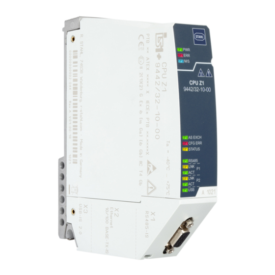
Anhang B Anhang B 15.1 Geräteaufbau Gerätelement Beschreibung Sicherungs- Torx T20 zum schraube Befestigen am Sockel LEDs Status- bzw. Fehleranzeige der CPU LEDs Status- bzw. Fehleranzeige der Kommunikation zum Automatisierungs- system LEDs Statusanzeige der Schnittstellen 23116E00 Sub-D-Buchse RS485 Buchse X1 Prozessbus Beschriftung Angaben zum Modul... -
Page 30: 15.2 Maßangaben / Befestigungsmaße
Anhang B 15.2 Maßangaben / Befestigungsmaße Maßzeichnungen (alle Maße in mm [Zoll]) – Änderungen vorbehalten 158 [6,22] 22970E00 22971E00 CPU Modul 9442/32 CPU Modul 9442/32 mit Sockel 9496/32 (3 Steckplätze) 23022E00 CPU Modul 9442/32 mit Sockel 9496/32 (4 Steckplätze) CPU Modul für Zone 1 279954 / 944260310110 Reihe 9442/32 2022-05-04·BA00·III·de·00... -
Page 31: Anhang C
Anhang C 16.1 Information zu Open Source Software Die IS1+ 9442 CPUs der R. STAHL Schaltgeräte GmbH (im folgenden "R. STAHL") und die auf der Website von R. STAHL erhältlichen Software-Updates enthalten neben proprietärer Software auch Software von Dritten, einschließlich freier Software/Open Source Software, die unter verschiedenen Lizenzbedingungen, einschließlich GNU GPLv2, GNU GPLv3,... - Page 33 Operating instructions Additional languages r-stahl.com CPU module for Zone 1 Series 9442/32...
- Page 34 Contents Contents General Information .....................3 Manufacturer......................3 About these Operating Instructions..............3 Further Documents ....................3 Conformity with Standards and Regulations............3 Explanation of Symbols ..................4 Symbols used in these Operating Instructions.............4 Symbols on the Device ..................4 Safety........................5 Intended Use......................5 Personnel Qualification ..................5 Residual Risks .....................6 Transport and Storage ..................8 Product Selection and Project Engineering ............8 Terminal Assignment for Sub-D Slot X1 ..............9...
-
Page 35: General Information
Make the operating instructions accessible to operating and maintenance staff at all times. ▶ Pass the operating instructions on to each subsequent owner or user of the device. ▶ Update the operating instructions every time R. STAHL issues an amendment. ID no.: 279954 / 944260310110 Publication code: 2022-05-04·BA00·III·en·00... -
Page 36: Explanation Of Symbols
Explanation of Symbols Explanation of Symbols Symbols used in these Operating Instructions Symbol Meaning Handy hint for making work easier Dangerous situation which can result in fatal or severe injuries DANGER! causing permanent damage if the safety measures are not complied with. -
Page 37: Se Fi
Specialists who perform these activities must have a level of knowledge that meets applicable national standards and regulations. Additional knowledge is required for any activity in hazardous areas! R. STAHL recommends having a level of knowledge equal to that described in the following standards: •... -
Page 38: Residual Risks
▶ Do not place any loads on the device. ▶ Check the packaging and the device for damage. Report any damage to R. STAHL immediately. Do not commission a damaged device. ▶ Store the device in its original packaging in a dry place (with no condensation), and make sure that it is stable and protected against the effects of vibrations and knocks. - Page 39 Only connect compatible components (IS1+/IS1 Remote I/O system). If in doubt, consult R. STAHL. ▶ Repair work on the device must be performed only by R. STAHL. ▶ Gently clean the device with a damp cloth only – do not use scratching, abrasive or aggressive cleaning agents or solutions.
-
Page 40: Gr 4 Transport And Storage
Transport and Storage 3.3.2 Damage to electrical Components Sensitive electronic components can be damaged by electrostatic discharge (ESD). ▶ Before making contact with the device, discharge the charge to a grounded metal body. ▶ Avoid direct contact with connectors or the contacts on the module slots. ▶... -
Page 41: Terminal Assignment For Sub-D Slot X1
Product Selection and Project Engineering Equipping and permissible mounting conditions DANGER! Explosion hazard due to incorrect electrical project engineering! Non-compliance results in fatal or severe injuries. ▶ Only plan and connect intrinsically safe connections for the CPU module. • Adhere to maximum equipping and module assignment per socket: - For a socket with three slots: 2 CPU modules and 1 power module (CPU redundancy) or 1 CPU module and 2 power modules (power redundancy) -
Page 42: Terminal Assignment X2 Rj45 Slots
Product Selection and Project Engineering Terminal Assignment X2 RJ45 Slots For connecting the primary and secondary network to the Modbus TCP / EtherNet/IP / PROFINET. Pin pair Pin no. Function Description – Not connected – Not connected Receive Data + Receive Data - Transmit Data + 19623E00... -
Page 43: Redundancy
Product Selection and Project Engineering Redundancy The IS1+ Remote I/O system can also be implemented redundantly based on the communication protocol. Here, a distinction is made between CPU redundancy, power redundancy and system/full redundancy. Comply with the specifications for selecting the suitable 9496/32 socket and maximum equipping of the 9442/32 CPU module and 9445/32 power module! The following table shows the components required for the respective redundancy concepts: 9496/32 socket... - Page 44 Product Selection and Project Engineering 5.4.1 Firmware Version in Redundancy Operation In redundancy operation, it is generally recommended that both 9442 CPU modules (primary and secondary module) have the same firmware version. Compare current and older firmware versions A new CPU module is always delivered with the latest firmware version. It may differ from the version already used by an older module.
-
Page 45: Mounting And Installation
Mounting and Installation Mounting and Installation DANGER! Explosion hazard due to incorrect mounting! Non-compliance results in severe or fatal injuries! ▶ Only mount the device on clean contact surfaces. ▶ Fit the device using safety screws. ▶ Tighten the safety screws using a tightening torque of 1.5 to 1.9 Nm. Mounting/Dismounting ▶... -
Page 46: Replacing And Upgrading The Module
Mounting and Installation Replacing and Upgrading the Module 6.2.1 Replacing the 9442/32 CPU Module ▶ Switch off the power supply to the IS1+ Remote I/O system. ▶ Disconnect the connection lines for communication (RJ45, Sub-D and USB). ▶ Use a screwdriver (Torx T20) to unscrew the safety screw (1), swivel the module forward and out (2) and disconnect it from the socket (3). - Page 47 Mounting and Installation 6.2.3 Upgrading the 9441/12 IS1 Ethernet CPU Series to 9442/32 IS1+ CPU ▶ Switch off the power supply to the IS1 Remote I/O station. ▶ Disconnect the connection lines for communication (FO) (see 9441/12 operating instructions). ▶ Dismount the 9441/12 IS1 Ethernet CPU, 9444/12 power module and 9492 socket (see operating instructions for 9441/12 CPU, 9444 power module and 9492 socket).
- Page 48 Mounting and Installation 6.3.1 Connecting the Intrinsically Safe Fieldbus Line For use in hazardous areas, a suitable fieldbus isolating repeater (e.g. series 9185) must be used between the intrinsically safe fieldbus connection (X1) and the automation system. ▶ 23119E00 Connect the fieldbus conductor with Sub-D plug to the X1 Sub-D slot. ▶...
- Page 49 Mounting and Installation ▶ Connect the primary Ethernet line with locking hook on the standard RJ45 plug connector to the X2P1 RJ45 socket until it audibly engages. ▶ Connect the secondary Ethernet line with locking hook on the standard RJ45 plug connector to the X2P2 RJ45 socket until it audibly engages.
-
Page 50: Parameterisation And Commissioning
Parameterisation and Commissioning Parameterisation and Commissioning Before commissioning, carry out the following checks: ▶ Mounting and installation of the device according to regulations. ▶ Correct, secure connection of the connection lines. ▶ No damage to the device and the connection lines. ▶... -
Page 51: Troubleshooting
Operation Troubleshooting Error notifications can be read out using the IS1+ detect tool. Status or error indication of the CPU LED status Status Cause of error Troubleshooting "PWR" LED Operation No error – (green) lights up indication "PWR" LED Software update No error Wait for the software (green) blinking update to finish... - Page 52 Operation LED status Status Cause of error Troubleshooting "M/S" LED (blue) Outside the Software update Wait for the software specification update to finish "PWR OUT" LED (green) are blinking "M/S" LED (blue) No maintenance No error – is off required Status or error indication of communication to the automation system LED status Status...
- Page 53 Ethernet line If the error cannot be eliminated using the specified procedures: ▶ Contact R. STAHL Schaltgeräte GmbH. For rapid processing, have the following information ready: • Type and serial number of the device • DCS/PLC • Protocol •...
-
Page 54: Maintenance, Overhaul, Repair
Returning the Device ▶ Only return or package the devices after consulting R. STAHL! Contact the responsible representative from R. STAHL. R. STAHL's customer service is available to handle returns if repair or service is required. ▶ Contact customer service personally. ▶... -
Page 55: Cleaning
NOTICE! Malfunction or damage to the device due to the use of non-original components. Non-compliance can result in material damage. ▶ Use only original accessories and spare parts from R. STAHL Schaltgeräte GmbH (see data sheet). 279954 / 944260310110 CPU module for Zone 1 2022-05-04·BA00·III·en·00... - Page 56 Appendix A Appendix A 14.1 Technical Data Explosion protection Global (IECEx) IECEx PTB 22.0001X Ex ib [ia Ga] [ib Gb] IIC T4 Gb [Ex ia Da] [Ex ib Db] IIIC Europe (ATEX) PTB 21 ATEX 2004 X E II 2 (1) (2) G Ex ib [ia Ga] [ib Gb] IIC T4 Gb E II (1) (2) D [Ex ia Da] [Ex ib Db] IIIC Certificates and approvals Certifications...
- Page 57 Appendix A Explosion protection X2 10/100-BASE-TX-IS interface According to type of [Ex ia Ga] IIC and [Ex ia Da] IIIC protection Note: Galvanically separated installation of communication lines; the shield can be grounded according to IEC/EN 60079-14. It is a point-to-point connection. The persistent current on the signal lines is protected internally at max.
-
Page 58: Technical Data
Appendix A Technical data Electrical data Power supply Over the 9496/32 socket and 9445/32 power modules Max. power dissipation Max. current 0.3 A consumption Interfaces X1 RS485 interface (RS485-IS) Connection Sub-D plug, 9-pole Line termination Powered resistor (end-of-line resistor in the Sub-D plug, see accessories) Protocols PROFIBUS DP V1 HART, PROFIBUS DP V1 HART + PNO red. - Page 59 Manufacturer, type, hardware revision, software revision, serial number parameters Connectable • IS Wizard (using the USB ServiceBus) software packages • R. STAHL DTM devices with FDT frames (e.g. FDT container by M+M; PACTware) • AMS from Emerson Process Management • PDM from Siemens •...
- Page 60 9496/32-04 CPU module with socket: L = 167 mm, W = 152 mm, H = 152 mm Mounting/installation Installation conditions Mounting type On 9496/32 socket Mounting orientation Horizontal or vertical For further technical data, see r-stahl.com. CPU module for Zone 1 279954 / 944260310110 Series 9442/32 2022-05-04·BA00·III·en·00...
-
Page 61: 15.1 Device Design
Appendix B Appendix B 15.1 Device Design Device element Description Safety screw Torx T20 for mounting on the socket LEDs Status or error indication of the CPU LEDs Status or error indication of communication to the automation system LEDs Status indication of the interfaces Sub-D socket X1 RS485 Sub-D... -
Page 62: 15.2 Dimensions/Fastening Dimensions
Appendix B 15.2 Dimensions/Fastening Dimensions Dimensional drawings (all dimensions in mm [inch]) – Subject to change 158 [6,22] 22970E00 22971E00 9442/32 CPU module 9442/32 CPU module with 9496/32 socket (3 slots) 23022E00 9442/32 CPU module with 9496/32 socket (4 slots) CPU module for Zone 1 279954 / 944260310110 Series 9442/32... -
Page 63: 16.1 Information Regarding Open Source Software
We shall not be held liable for any damage resulting from modifications to parts of the software or their configuration that were not carried out by R. STAHL. In addition, R. STAHL shall not be held liable if the open source software infringes on the copyright of a third party.
Need help?
Do you have a question about the IS1+ 9442/32 Series and is the answer not in the manual?
Questions and answers