Table of Contents
Advertisement
Quick Links
ARCHIMEDE
5000 Series
High Power FM Amplifier
RFP
MAIN MENU
TURN AND PUSH TO SELECT
Ultra-compact High Power FM Amplifiers
ITALAB COMMUNICATIONS Via Casale 3/a - 20144 Milano- Italy
Tel. +39 02 0290389417 – email: info@italab.it – www.italab.it
User's Manual
Revision 1.0
VHF FM POWER AMPLIFIER
ARCHIMEDE 5000
ALARM
STAND BY
ON
START STOP
DESIGN BY LAURA MICALIZZI
Advertisement
Chapters
Table of Contents

Related Manuals for ITB ARCHIMEDE 5000 Series

Summary of Contents for ITB ARCHIMEDE 5000 Series
- Page 1 ARCHIMEDE 5000 Series High Power FM Amplifier VHF FM POWER AMPLIFIER ARCHIMEDE 5000 ALARM STAND BY START STOP MAIN MENU TURN AND PUSH TO SELECT DESIGN BY LAURA MICALIZZI Ultra-compact High Power FM Amplifiers User’s Manual Revision 1.0 ITALAB COMMUNICATIONS Via Casale 3/a - 20144 Milano- Italy Tel.
- Page 2 Archimede 5000 series- FM Power Amplifiers Preliminary notes We used the utmost care in making a complete manual with detailed, accurate and updated information, yet the contents herein cannot be regarded as totally binding towards our company. Italab, in their constant commitment to improve the quality of their products, reserve the right to vary the technical features of the same without prior notice.
-
Page 3: Table Of Contents
Archimede 5000 series- FM Power Amplifiers Contents ......................... 5 NTRODUCTION ......................6 ENERAL NFORMATION Safety suggestions ........................6 2.1.a General safety recommendations ....................... 6 2.1.b Good practices ............................ 7 2.1.c First aid in case of electrical shock ..................... 7 2.1.d Emergency resuscitation technique ....................7 2.1.e Treatment for burns .......................... - Page 4 Archimede 5000 series- FM Power Amplifiers ........................ 34 SE OF THE MENUS Use of the multifunction knob ..................... 34 Navigating the menu ........................34 Confirming/quitting the settings ....................35 ........................ 36 ENU DESCRIPTION 10.1 Startup page ..........................36 10.2 Working Page ..........................36 10.3 Main menu ..........................
-
Page 5: Introduction
Archimede 5000 series- FM Power Amplifiers N TR O D U C TI O N Congratulations for your choice! Archimede High Power is a series of new-concept FM solid state (MOS-FET) amplifiers, available in three different models according to their rated output power (Archimede 3000 3kW - Archimede 4000 4kW – Archimede 5000 ... -
Page 6: General Information
Don't take chances. Be fully trained. Italab ( ITB ) equipments should be operated and maintained by fully qualified personnel. Do not service alone and do not perform internal adjustments of these units unless another person capable of rendering first aid and resuscitation is present. -
Page 7: Good Practices
Archimede 5000 series- FM Power Amplifiers 2.1.b Good practices In maintaining the equipment covered in this manual, please keep in mind the following, standard good practices: When connecting any instrument (wattmeter, spectrum analyzer, etc.) to a high frequency output, use the appropriate attenuator or dummy load to protect the final amplifiers and the instrument input. -
Page 8: Treatment For Burns
Archimede 5000 series- FM Power Amplifiers Step 4 Put the fingertips of your hand on the Adam's apple, slide them into the groove next to the windpipe. Feel for a pulse. If you cannot feel a pulse or are unsure, move on to the next step. -
Page 9: Symbols Used In This Document
Archimede 5000 series- FM Power Amplifiers Symbols used in this document In order to allow a quick and essential reading, we used symbols which attract immediate attention, and which simply and efficiently advise and inform the user. The symbol of the open hand, stresses a description of the highest importance, which concerns technical intervention, dangerous situations, security warnings, advice and/or information of the highest importance. -
Page 10: Warnings
Archimede 5000 series- FM Power Amplifiers AR N I N G S Safety first! Before connecting or using these devices, carefully read all instructions contained in this manual, in the order in which they are written. Cross references to sections and chapters were created exclusively for ease of use. Keep this manual in a safe place for future reference. -
Page 11: Model Identification
Archimede 5000 series- FM Power Amplifiers O D E L I D E N T IF IC AT IO N The features of the Archimede High Power series FM amplifiers (such as the commands on the front panel) are common to all models. -
Page 12: Parts Description
Archimede 5000 series- FM Power Amplifiers AR T S D E S C R IP T I O N If not otherwise specified, the following descriptions are valid for all Archimede High Power models. Front view Please see the following images to spot and identify the equipment parts and get familiar with them:... -
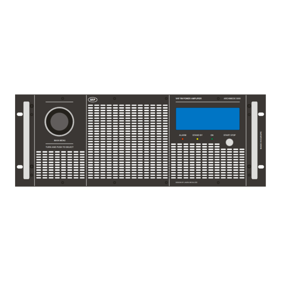
Page 13: Control Panel
Archimede 5000 series- FM Power Amplifiers 5.1.a Control panel The control panel commands are the followings: VHF FM POWER AMPLIFIER ARCHIMEDE 5000 ALARM STAND BY START STOP MAIN MENU LCD (Liquid Crystal Display) – this display, composed of 4 lines of 20 characters, shows the operation parameters and functions selected through the multifunction knob. -
Page 14: Rear View
Archimede 5000 series- FM Power Amplifiers Rear view Archimede 3000 and Archimede 4000 rear view (standard version, for the connection to a single-phase 230V power line): G ND Archimede 5000 rear view: I T B [12] Exhaust cooling air outlet – the exhaust cooling air which came into the equipment through the front ventilation grid exits from this outlet [13] RS 232 connector –... -
Page 15: Input Rf Power, Max Levels
Archimede 5000 series- FM Power Amplifiers When installing Archimede 5000 or Archimede 4000 models make sure to earth the equipment through the ground wire of the power supply cable (7.4.c). [16] Power Supply cable – Archimede 3000 standard model can be connected to a single-phase 230V power line. -
Page 16: Remote Connector
Archimede 5000 series- FM Power Amplifiers 5.2.a REMOTE connector The REMOTE connector [14] gathers mainly information about the equipment status (alarms status and internally carried measures). The following table describes these I/O signals: Signal Description/Notes (not connected) High reflected power alarm... -
Page 17: Internal Top View - Main Parts Location
Archimede 5000 series- FM Power Amplifiers Internal top view - main parts location. Archimede 3000/4000 Archimede 5000 Rear side Rear side Front side Front side [22] ON/OFF power switch [23] Fans control board (Par.6.3). [24] Analog & controls board (Par.6.2). -
Page 18: Internal Bottom View (R.f. Amplifier Section) - Main Parts Location
Archimede 5000 series- FM Power Amplifiers Internal bottom view (R.F. amplifier section) - main parts location. If not otherwise specified, the following descriptions are valid for all Archimede High Power models. Rear side Front side [29] Driver amplifier (Par.6.4.a). -
Page 19: Circuits Description
Archimede 5000 series- FM Power Amplifiers I R C U I TS D E SC R I PT IO N This section’s sole purpose is to provide general explanations about the device operation in order to simplify the maintenance by skilled personnel appointed by Italab. As already mentioned, no internal adjustments are required for normal operation. -
Page 20: Power Supply Unit Connections And Indications
Archimede 5000 series- FM Power Amplifiers 6.1.a Power supply unit connections and indications [41] Mains voltage input. [42] Power Supply unit status LEDs. Analog & controls board This board (Par. 5.3, part # [24]) manages all the equipment protections (Direct, Reflected and Max output R.F. powers) via the output power loop control and the reflected power loop control. -
Page 21: Analog Board Connections
Archimede 5000 series- FM Power Amplifiers 6.2.b Analog board connections [43] Exciter enabling/disabling command output – this signal (relay contacts) manages the Exciter power supply. Only with Archimede 3000 and Archimede 4000. power supply for the amplifier module #4 – the (black) power resistor is used for the current measurement. Only with [44] 48V Archimede 4000 and Archimede 5000. -
Page 22: R.f. Amplifier Section
Archimede 5000 series- FM Power Amplifiers [55] 48V power supply input. [56] Power supply outputs for the cooling fans. [57] Power supply outputs for the fans cooling R.F. amplifier heatsink. [58] Data bus from the R.F. amplifier section – this flat cable sends data referred to the operation of the R.F. amplifier section. -
Page 23: Amplifier Circuits
Archimede 5000 series- FM Power Amplifiers [59] R.F. signal input (5W) – coming from the RF IN connector [19]. [60] R.F. signal output – connected to the Wilkinson Splitter board. 6.4.b Amplifier circuits The R.F. signal from the Driver amplifier enters first the Wilkinson splitter ( Par.5.4 - part # [30]) . This circuit splits the R.F. signal into three or four outputs, according to the model: ... -
Page 24: Protection Fuses For The Amplifier Modules
Archimede 5000 series- FM Power Amplifiers 6.4.c Protection fuses for the amplifier modules The Archimede High Power series mounts fuses ( Par. 5.4 - parts # [39] and [40]) to protect the two transistors of each amplifier module. In total, there are: ... -
Page 25: Input/Direct/Reflected Power Levels Readings Adjustment Circuit
Archimede 5000 series- FM Power Amplifiers 6.4.d Input/Direct/Reflected power levels readings adjustment circuit This circuit ( Par. 5.4 - part # [38]) mounts trimmers used to adjust the input, direct and reflected power readings shown on the LCD display: [69] Reflected Power reading adjustment – use this trimmer to adjust the reflected power level reading. -
Page 26: Extraction Of Direct/Reflected Power Levels And Low-Level R.f. Signal
Archimede 5000 series- FM Power Amplifiers 6.4.e Extraction of direct/reflected power levels and low-level R.F. signal This circuit (Par.5.4 - part # [37]), mounts directional couplers, used to extract the direct and reflected power level signals and a low R.F. level from the output power signal: [72] Reflected power signal –... -
Page 27: Installation
Archimede 5000 series- FM Power Amplifiers N ST AL L A T I O N Warning: to ensure safe functioning of the equipment, it’s absolutely mandatory to comply with the instructions of the present chapter. Checking the supplied parts Before using your amplifier, make sure that the following parts are included in the packing: ... -
Page 28: Electrical Conditions
Archimede 5000 series- FM Power Amplifiers that the equipment internal fans are low-pressure units and therefore an air extractor on the air exhaust duct in definitely needed. Air conditioning at 20 – 25 °C would obviously be the best solution. Thermal insulation and efficient ventilation with a thermostat-controlled blower are generally the best solution. -
Page 29: Connection Of The Archimede 4000 Or Archimede 5000 Power Supply Cable
Archimede 5000 series- FM Power Amplifiers Never switch on the equipment without an antenna connection. 7.4.c Connection of the Archimede 4000 or Archimede 5000 power supply cable Carefully follow these information when connecting the power supply of Archimede 4000 or Archimede 5000 standard version:... -
Page 30: Basic Operations
Archimede 5000 series- FM Power Amplifiers AS I C O P E R ATIO N S If not otherwise specified, the following descriptions are valid for all Archimede High Power models. Turning on/turning off 8.1.a First switching on (during installation) ... -
Page 31: Setting The Display Language
Archimede 5000 series- FM Power Amplifiers Press the multifunction knob to select this menu and move the > cursor on the right of the power value (in this example 100 – see the following note): S e t F o r... - Page 32 Archimede 5000 series- FM Power Amplifiers Press the knob. The Set Clock menu will be shown (split in two pages): Turn the knob counterclockwise in order to move the cursor > downward to the left of Year. Press the knob. The cursor > will move to the right of Year and the year will become editable.
-
Page 33: Turning Off
Archimede 5000 series- FM Power Amplifiers 8.1.e Turning off Keep the ON/STANDBY button [6] pressed for a couple of seconds setting the equipment in stand-by mode. Turn off the Power ON/OFF switch [18] on the rear panel. User’s manual – Page 33 of 65... -
Page 34: Use Of The Menus
Archimede 5000 series- FM Power Amplifiers S E O F TH E M EN U S Use of the multifunction knob The multifunction knob is used to surf the menu with its submenus and set/check their parameters. It can be used in 3 ways: ... -
Page 35: Confirming/Quitting The Settings
Archimede 5000 series- FM Power Amplifiers The described commands are to be considered as standard actions (bear in mind that in some menus they are slightly different). For details about each single menu and how operate on it Chapt. 10 - Menu description. -
Page 36: En U D E S C R Ipt I O N
P w e r 2 4 A r 2 0 1 3 2 2 5 3 1 2 ITB ARCHIMEDE rev.1.6: model of the equipment and software revision Forward Power: forward power level Reflected Power: reflected power level ... -
Page 37: Set Power Output Menu
Archimede 5000 series- FM Power Amplifiers Working Page: leads back to the working page as over explained Set Power Output: sets the output power (10.4) Debug Page: reads some measurements, checks the knob/digital encoder operation and current alarms (10.5) ... -
Page 38: Logic Inputs Menu
Archimede 5000 series- FM Power Amplifiers The read-only Analog Inputs menu will show. It’s split in three pages and lists the results of internally carried out measurements: Forward Power: forward output power level Input Power: driving input power level ... -
Page 39: Encoder Test Menu
Archimede 5000 series- FM Power Amplifiers Encoder Test menu 10.5.c This menu allows to check the correct operation of the digital encoder connected to the knob. From the Debug Page (10.5), select Encoder Test: Press the knob. The Encoder Test menu will be shown: Turn the knob and check if the A and B values are changing. -
Page 40: Set Clock Menu
Archimede 5000 series- FM Power Amplifiers Turn the knob to change the LCD contrast and you will directly see the result of the adjustments. Here are some images showing how the contrast changes turning the knob: When the needed contrast level is set, press the knob. The cursor will move on the left: To confirm the entered settings, select Confirm Changes and press the knob (or, to quit the menu without changing the previous setting, select Ignore Changes and press the knob). -
Page 41: Set Function , Size Menu
Archimede 5000 series- FM Power Amplifiers MEN U U N C T I O N I Z E This multilevel technical menu allows to set the equipment as MASTER or SLAVE, set its power size (according to the model), check the time in which it worked in normal operation or other conditions and automatically reduce its output power in certain times. -
Page 42: Function Menu
Archimede 5000 series- FM Power Amplifiers Power Size: power size according to the rated value of each model (11.1.b) Show timers: time in normal operation, alarm or stand-by mode (11.1.c) Set power saver: power saver time settings (11.1.d) ... -
Page 43: Show Timers Menu
Archimede 5000 series- FM Power Amplifiers Show Timers menu 11.1.c This option allows to see a page showing the number of working hours, hours with active alarms, stand by hours In the program page (11.1), turn counterclockwise the knob scrolling down until Show timers: Press the knob, the Show timers menu is shown: ... -
Page 44: Set A New Password Menu
Archimede 5000 series- FM Power Amplifiers Turn the knob to set the start time, then press the knob to confirm. The cursor will move back on the left of Start: Move the cursor to the left of End h. m. in order to set the end time (see warning at the bottom). -
Page 45: Forgotten Password
Archimede 5000 series- FM Power Amplifiers Repeat the last step until all the six digits has been set. press the knob to enter the whole new password. The display will lead to the main menu. Note down the new password in a secure place. -
Page 46: Aintenance And Warranty
Archimede 5000 series- FM Power Amplifiers 12 M AI N TE N AN C E A N D W AR R A N T Y 12.1 Maintenance Strictly follow what is written in this chapter. 12.1.a Clogging by dust Since the equipment is air cooled, it is subject to clogging by dust. -
Page 47: Roubleshooting And Alarms
Archimede 5000 series- FM Power Amplifiers 13 T R O U B L E S H O O T I N G AN D A L AR M S If all instructions described in this manual are followed, the equipment will guarantee several years of perfect service. However, should problems arise, see this chapter before contacting the local authorized assistance point. -
Page 48: Echnical Features
Archimede 5000 series- FM Power Amplifiers 14 T E C H N I C AL F E AT U R ES Feature Archimede 3000 Archimede 4000 Archimede 5000 87.5 108MHz Frequency range Modulation Input power 35W MAX 50W MAX... -
Page 49: Ndex
Archimede 5000 series- FM Power Amplifiers 15 I N D E X Alarms First aid ..............7 LEDs information ............ 47 Forgotten password ........... 45 type of ..............47 Fuses location ............ 24 Antenna connection .............. 28 General safety recommendations ......6 General safety rules ........... - Page 50 Archimede 5000 series- FM Power Amplifiers working page ............36 Menus REMOTE connector ........... 16 use of ..............34 RF IN Model identification ..........11 maximum input power ..........29 Multifunction knob ..........13 RF Output connector .......... 15 use of the ............... 34 Safety Navigating the menu ..........
-
Page 51: Electrical , Mechanical Diagrams And Parts Location
Archimede 5000 series FM amplifiers 16 E L EC TR I C AL M E C H AN IC AL D I AG R AM S AN D P AR T S L O C AT I O N Figure 1 – Archimede High Power series Front view ................... 52 Figure 2 –... - Page 52 Figure 1 – Archimede High Power series Front view VHF FM POWER AMPLIFIER ARCHIMEDE 5000 ALARM STAND BY START STOP MAIN MENU TURN AND PUSH TO SELECT DESIGN BY LAURA MICALIZZI User’s manual – Page 52 of 65 Archimede 5000 series FM amplifiers...
- Page 53 Figure 2 – Archimede 3000 and Archimede 4000 Rear view G ND User’s manual – Page 53 of 65 Archimede 5000 series FM amplifiers...
- Page 54 Figure 3 – Archimede 5000 Rear view I T B User’s manual – Page 54 of 65 Archimede 5000 series FM amplifiers...
- Page 55 Figure 4 – Archimede 3000/4000 Top view (open) Note: Archimede 4000 standard version mounts a third power supply unit, located in the central position (between the two shown power supply units) User’s manual – Page 55 of 65 Archimede 5000 series FM amplifiers...
- Page 56 Figure 5 – Archimede 5000 Top view (open) User’s manual – Page 56 of 65 Archimede 5000 series FM amplifiers...
- Page 57 Note: the fourth amplifier module (the lowest in this image) is mounted only on Archimede 4000 and Archimede 5000. For details about the R.F. Amplifier section differences among the three models User’s manual – Page 57 of 65 Archimede 5000 series FM amplifiers...
- Page 58 Figure 7 – Power Supply unit – Circuit diagram 1/7 User’s manual – Page 58 of 65 Archimede 5000 series FM amplifiers...
- Page 59 Figure 8 – Power Supply unit – Circuit diagram 2/7 User’s manual – Page 59 of 65 Archimede 5000 series FM amplifiers...
- Page 60 Figure 9 – Power Supply unit – Circuit diagram 3/7 User’s manual – Page 60 of 65 Archimede 5000 series FM amplifiers...
- Page 61 Figure 10 – Power Supply unit – Circuit diagram 4/7 User’s manual – Page 61 of 65 Archimede 5000 series FM amplifiers...
- Page 62 Figure 11 – Power Supply unit – Circuit diagram 5/7 User’s manual – Page 62 of 65 Archimede 5000 series FM amplifiers...
- Page 63 Figure 12 – Power Supply unit – Circuit diagram 6/7 User’s manual – Page 63 of 65 Archimede 5000 series FM amplifiers...
- Page 64 Figure 13 – Power Supply unit – Circuit diagram 7/7 User’s manual – Page 64 of 65 Archimede 5000 series FM amplifiers...
- Page 65 User’s manual – Page 65 of 65...
Need help?
Do you have a question about the ARCHIMEDE 5000 Series and is the answer not in the manual?
Questions and answers