Table of Contents
Advertisement
Quick Links
Advertisement
Table of Contents

Related Manuals for Kongsberg Simrad C-All

Summary of Contents for Kongsberg Simrad C-All
- Page 1 INSTALLATION MANUAL Simrad C-All kongsberg.com/simrad...
- Page 3 Additional end-user documents related to the C‑All transducer can be found on our website. This includes publications that are translated to other languages. Selected publications are also provided on IETM (Interactive Electronic Technical Manual) formats. • www.kongsberg.com/c-all 479237/A March 2022 © Kongsberg Maritime AS...
- Page 4 Kongsberg Maritime disclaims any responsibility for damage or injury caused by improper installation, use or maintenance of the equipment. Disclaimer Kongsberg Maritime AS endeavours to ensure that all information in this document is correct and fairly stated, but does not accept liability for any errors or omissions. Support information If you require maintenance or repair, contact your local dealer.
-
Page 5: Table Of Contents
Installation Manual Table of contents ABOUT THIS MANUAL .............. 5 INTRODUCTION............... 7 Simrad C‑All........................8 Physical and environmental specifications ................9 Order information ......................10 Support information ......................10 TRANSDUCER HANDLING AND MAINTENANCE....... 13 Rules for transducer handling ..................14 Inspecting and cleaning the transducer face ..............15 Painting the transducer face .....................17 Approved anti-fouling paints ...................19 PREPARATIONS .............. - Page 6 Simrad C‑All Electrical self noise ....................44 Some means to reduce acoustic noise ..............44 INSTALLING THE TRANSDUCER ..........47 Installation summary......................48 Using a suitable inclination angle ................50 Smooth surface is important...................50 Using self-locking taps ...................51 Designing, manufacturing and mounting the installation hardware ........53 Installing the cable gland ....................55 Designing, manufacturing and mounting the steel conduit ..........56 Unpacking the transducer from its transport crate............58...
-
Page 7: About This Manual
The shipowner and shipyard doing the installation are responsible for obtaining and paying for such approval. Kongsberg Maritime AS will accept no responsibility for any damage or injury to the product, vessel or personnel caused by equipment that has been incorrectly installed or maintained, or by drawings, instructions or procedures that have not been prepared by us. - Page 8 , SIMRAD ® and the Simrad ® logo are either registered trademarks, or trademarks of Kongsberg Maritime AS in Norway and other countries. We want your feedback We always want to improve our products. We also want our end-user documentation to be comprehensive and relevant.
-
Page 9: Introduction
Introduction Introduction Topics Simrad C‑All, page 8 Physical and environmental specifications, page 9 Order information, page 10 Support information, page 10 479237/A... -
Page 10: Simrad C-All
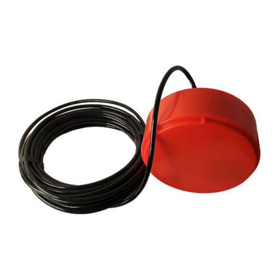
Simrad C‑All Installation Manual Simrad C‑All The Simrad C-All is a single beam transducer designed for fish finding applications. The transducer body includes four different transducer elements providing four operational frequencies: 38, 70, 120 and 200 kHz. The beamwidth is 18 degrees at each nominal operating frequency. -
Page 11: Physical And Environmental Specifications
Introduction Physical and environmental specifications These physical and environmental specifications are important for handling, storage and installation. Note We are continuously working to improve the quality and performance of our products. The technical specifications may be changed without prior notice. Weights and outline dimensions •... -
Page 12: Order Information
A list of all our offices and dealers is available on our website. You can also contact our main support office in Norway. Norway (main office) • : Kongsberg Maritime AS / Simrad Company name • : Strandpromenaden 50, N3190 Horten, Norway Address •... - Page 13 Telefax • www.kongsberg.com/simrad Website • simrad.france@simrad.com Email address • : Kongsberg Underwater Technology LLC (KUTL) / Simrad Fisheries Company name • : 19210 33rd Ave W, Suite A, Lynnwood, WA 98036, USA Address • : +1 425 712 1136 Telephone •...
- Page 14 Simrad C‑All Installation Manual China • : Kongsberg Maritime China Ltd Company name • : 555 Chuanqiao Road, China (Shanghai) Pilot Free Trade Zone, 201206, China Address • : +86 21 3127 9888 Telephone • : +86 21 3127 9555 Telefax •...
-
Page 15: Transducer Handling And Maintenance
Transducer handling and maintenance Transducer handling and maintenance Topics Rules for transducer handling, page 14 Inspecting and cleaning the transducer face, page 15 Painting the transducer face, page 17 Approved anti-fouling paints, page 19 479237/A... -
Page 16: Rules For Transducer Handling
Simrad C‑All Installation Manual Rules for transducer handling To secure long life and accurate results, the transducer must be handled correctly. A transducer must always be handled as a delicate instrument. Incorrect actions may damage the transducer beyond repair. Observe these transducer handling rules: Do not activate the transducer when it is out of the water. -
Page 17: Inspecting And Cleaning The Transducer Face
The anti-fouling paint will reduce the acoustical performance of the transducer. The surface roughness of the transducer substrate and the thickness of the paint may also influence the performance. Kongsberg Maritime cannot be held responsible for any negative consequences of the anti-fouling paint. - Page 18 Simrad C‑All Installation Manual opportunity arise, typically when the vessel is dry-docked, the transducer face must be cleaned for shells and other marine growth. It is important to check the transducer for physical damage. Any cracks, fractures or holes in the red protective coating may result in a water leak, and a leak may cause irreparable damage to the transducer.
-
Page 19: Painting The Transducer Face
Because some paint types may be aggressive to the polyurethane in the transducer, consult our list of approved paints. The list of approved anti-fouling paints can be found on our website. • https://www.kongsberg.com/anti-fouling-paints Related topics Transducer handling and maintenance, page 13 Approved anti-fouling paints, page 19 Painting the transducer face Marine growth (biological fouling) on the transducer face reduces the performance. - Page 20 The anti-fouling paint will reduce the acoustical performance of the transducer. The surface roughness of the transducer substrate and the thickness of the paint may also influence the performance. Kongsberg Maritime cannot be held responsible for any negative consequences of the anti-fouling paint.
-
Page 21: Approved Anti-Fouling Paints
The list of approved anti-fouling paints can be found on our website. Always refer to the manufacturer's documentation and data sheets for a complete procedure and for relevant safety information. • https://www.kongsberg.com/anti-fouling-paints Important Do not paint the transducer with traditional hull plating paint. Use only the correct type of approved paint specified. -
Page 22: Preparations
Simrad C‑All Installation Manual Preparations Topics Installation summary, page 21 About installation drawings, page 22 Tools, equipment and consumables required for installation, page 22 Personnel qualifications, page 23 Transducer installation principles, page 24 Where to install the transducer, page 33 Acoustic noise, page 39 479237/A... -
Page 23: Installation Summary
Preparations Installation summary Installation of the C‑All system is a demanding task that requires careful preparations, a number of specific procedures, wiring and required system settings. Context An overall installation procedure is provided. This procedure does not describe any detailed tasks. Refer to the relevant tasks in this manual. Note In order to obtain maximum safety and optimal performance, it is very important that the installation procedures in this manual are complied to. -
Page 24: About Installation Drawings
The shipowner and shipyard doing the installation are responsible for obtaining and paying for such approval. Kongsberg Maritime offers free advice for installation planning. Proposed arrangements may be sent for commentary or suggestions. The following drawings should be submitted should assistance be requested: •... -
Page 25: Personnel Qualifications
Preparations various sizes. We recommend that all tools are demagnetized to protect your equipment. However, you must make sure that the following specialized tools are available. • All necessary tools and consumables required for mechanical work • All necessary tools and consumables required for welding •... -
Page 26: Transducer Installation Principles
Simrad C‑All Installation Manual Transducer installation principles Topics Transducer installation in a blister, page 24 Transducer installation in a flush mounted steel tank, page 27 Transducer installation in keel box, page 29 Transducer installation using drop keel, page 30 Smooth surface is important, page 32 Using a suitable inclination angle, page 32 Transducer installation in a blister A recommended method for transducer installation is by using a blister. - Page 27 Preparations during vessel movements in rough sea. This is an important security precaution to prevent damage to the transducer. The transducer cable penetrates the hull using a cable gland. The cable gland consists of a bushing, rubber gasket, washers and a packing nipple. Leave an adequate loop of the cable over the transducer body inside the blister for easy mounting or removal of the transducer.
- Page 28 Make sure that the "Forward" direction on transducer points in the forward direction of the vessel. Suitable mounting and clamping rings can be provided by Kongsberg Maritime. Drawings are available for local manufacturing. End user manuals and source drawings (normally in AutoCad format) can be downloaded from our website.
-
Page 29: Transducer Installation In A Flush Mounted Steel Tank
Preparations However, if the blister is located close to the bow, the front of the blister should have a few degrees "toe-in" towards the bow. Keel Blister Toe-in angle The angle must be chosen to allow for most efficient water flow It will vary with the location of the transducer;... - Page 30 Make sure that the "Forward" direction on transducer points in the forward direction of the vessel. Suitable mounting and clamping rings can be provided by Kongsberg Maritime. Drawings are available for local manufacturing. End user manuals and source drawings (normally in AutoCad format) can be downloaded from our website.
-
Page 31: Transducer Installation In Keel Box
Make sure that the "Forward" direction on transducer points in the forward direction of the vessel. Suitable mounting and clamping rings can be provided by Kongsberg Maritime. Drawings are available for local manufacturing. End user manuals and source drawings (normally in AutoCad format) can be downloaded from our website. -
Page 32: Transducer Installation Using Drop Keel
Simrad C‑All Installation Manual Smooth surface is important Make sure that the surface of the transducer face, as well as the plating and putty around the transducer is as even and smooth as possible. Obstructions on these surfaces will create problems with turbulent flow, and may cause noise. Note Mounting screws or bolts must not be extruding from the transducer or the plating immediately around it. - Page 33 Make sure that the "Forward" direction on transducer points in the forward direction of the vessel. Suitable mounting and clamping rings can be provided by Kongsberg Maritime. Drawings are available for local manufacturing. End user manuals and source drawings (normally in AutoCad format) can be downloaded from our website.
-
Page 34: Smooth Surface Is Important
Simrad C‑All Installation Manual Smooth surface is important Make sure that the surface of the transducer face, as well as the plating and putty around the transducer is as even and smooth as possible. Mounting screws or bolts must not be extruding from the transducer or the plating immediately around it. -
Page 35: Where To Install The Transducer
Preparations Where to install the transducer Topics Introduction to transducer location, page 33 Mount the transducer deep, page 33 Avoid protruding objects near the transducer, page 34 Mount the transducer at forward part of hull to minimize the effects from the flow boundary water layer, page 35 Keep the transducer far away from the propellers, page 36 Mount the transducer at a safe distance from bow thruster(s), page 36... -
Page 36: Avoid Protruding Objects Near The Transducer
The effect of slamming can be reduced by mounting the transducer as deep as possible on the hull. Note Kongsberg Maritime AS takes no responsibility for any damages to the transducer, the cable or the mounting arrangement, caused by slamming. Related topics... -
Page 37: Mount The Transducer At Forward Part Of Hull To Minimize The Effects From The Flow Boundary Water Layer
Preparations extruding from the transducer, the installation hardware or the hull plating. If necessary, grind and polish all surfaces. Related topics Preparations, page 20 Where to install the transducer, page 33 Mount the transducer at forward part of hull to minimize the effects from the flow boundary water layer The upper water layers of the sea contain a myriad of small air bubbles created by the breaking waves. -
Page 38: Keep The Transducer Far Away From The Propellers
Simrad C‑All Installation Manual Related topics Preparations, page 20 Where to install the transducer, page 33 Keep the transducer far away from the propellers The propulsion propellers is the dominant noise source on most vessels. The noise is easily transmitted through the water. This noise may often reduce the overall performance of your C‑All transducer. -
Page 39: Summary And General Recommendations
Preparations Summary and general recommendations Some of the installation guidelines provided for transducer location may be conflicting. For this reason, each vessel must be treated individually in order to find the best compromise. In general, the most important factor is to avoid air bubbles in front of the transducer face. - Page 40 Simrad C‑All Installation Manual Transducer Hull length at water line Inclination angle Maximum 1/3 of the hull length at water line (C) This applies to the vessel in normal trim and speed. Important The transducer must not have a negative inclination angle compared to water flow. Do not place a transducer near protruding objects, and especially not close behind them.
-
Page 41: Acoustic Noise
Preparations Acoustic noise Topics Contributing factors, page 39 Self noise, page 41 Ambient noise, page 43 Fishing gear noise, page 44 Electrical self noise, page 44 Some means to reduce acoustic noise, page 44 Contributing factors Several factors are contributing to the performance of the hydroacoustic equipment used on board a vessel. - Page 42 Simrad C‑All Installation Manual The signal is the echo that we want to know something about, while the noise is any unwanted signals or disturbances. The echo must be detected in the noise and therefore it is necessary to keep the noise level as low as possible in order to obtain high echo interpretation.
-
Page 43: Self Noise
Preparations Related topics Preparations, page 20 Acoustic noise, page 39 Self noise Any vessel equipped with a hydroacoustic system (for example echo sounder or sonar) will produce more or less self noise. There are many sources of such self noise. It is necessary to analyse the different sources of self-noise on a vessel, and find out how each source can affect the noise level of the hydroacoustic instruments. - Page 44 Simrad C‑All Installation Manual Cavitation Cavitation is the formation of small air bubbles close to the transducer face. The bubbles appear because the local pressure becomes negative during parts of the acoustic pressure cycles. The cavitation threshold increases with the hydrostatic pressure.
-
Page 45: Ambient Noise
Preparations thickness depends on ships speed and on the roughness of the hull. All objects sticking out from the hull, or dents in the hull, will disturb the flow and will increase the thickness of the boundary layer. When the flow speed is high, the turbulence can be violent enough to destroy the integrity of the water. -
Page 46: Fishing Gear Noise
Simrad C‑All Installation Manual Related topics Preparations, page 20 Acoustic noise, page 39 Fishing gear noise Whenever your fishing gear is in use, it will create noise. A bottom trawl, for instance, is a considerable source of acoustic noise. Still, this noise from the fishing gear will seldom be a limiting factor for hull mounted sonars or echo sounders. - Page 47 Preparations Note The information here must be considered as general advice. Each system installation must be handled separately depending on the hull design and the other electrical and mechanical systems installed on the vessel. Reducing flow noise The shape of the transducer (or dome around it) must be as streamlined as possible.
- Page 48 Simrad C‑All Installation Manual Reducing rattle noise Ensure that no parts near the transducers can rattle as a result of water flow or vibrations. Reducing interference Interference from the transmission pulses from other hydroacoustic instruments on board the vessel is difficult to avoid. The problem may be reduced by choosing the working frequencies carefully and to some extent by separating the different transducers.
-
Page 49: Installing The Transducer
Installing the transducer Installing the transducer Topics Installation summary, page 48 Designing, manufacturing and mounting the installation hardware, page 53 Installing the cable gland, page 55 Designing, manufacturing and mounting the steel conduit, page 56 Unpacking the transducer from its transport crate, page 58 Installing the transducer cable, page 59 Mounting the transducer, page 61 Painting the transducer face, page 63... -
Page 50: Installation Summary
(normally in AutoCad format) can be downloaded from our website. • www.kongsberg.com/c-all The transducer is normally mounted flush with the hull plating. A clamping ring is used to secure the transducer body to a mounting ring. The mounting ring is welded into the hull plating. - Page 51 Installing the transducer Procedure Determine the physical location of the transducer. The decision must be based on: • The vessel drawings • The shape and properties of the hull Make sure that all possible considerations are made to reduce noise. Based on the shape of the transducer housing, and the mounting devices available, determine the installation method.
-
Page 52: Using A Suitable Inclination Angle
Simrad C‑All Installation Manual Using a suitable inclination angle Ideally, the transducer face should be mounted in parallel with the sea surface when the vessel is in normal trim, as this will provide the most accurate echo information. However, it is also very important that the water flow over the transducer face is laminar. In order to ensure laminar flow, the transducer face must be tilted slightly upwards in relation to the water flow. -
Page 53: Using Self-Locking Taps
Installing the transducer Using self-locking taps The mounting rings delivered by Kongsberg Maritime are fitted with self-locking threads. Normal screws are designed to be loosened. It is however important to avoid accidental loosening, especially when the installation is subjected to dynamic stress. For this reason, additional locking devices are required. - Page 54 The drawing is normally provided with the following - or similar - text: Drill diameters for threads differ from standard. Self-lock taps can be supplied by Kongsberg Maritime. Note Refer to manufacturer’s website for the latest drawings and information about the self-locking taps.
-
Page 55: Designing, Manufacturing And Mounting The Installation Hardware
Use Emuge self-lock gauges. Note that the gauge must be used in the correct direction. Self-lock taps provided by Kongsberg Maritime Several self-lock taps are on stock at Kongsberg Maritime, and can be ordered from us. Threads Drill diameter for threads Part number ø5.2 mm... - Page 56 Simrad C‑All Installation Manual • The installation method has been determined. • All relevant personnel (naval architects, designers, skilled shipyard workers) and tools must be available. Context The installation shipyard must provide all necessary installation drawings. If required, all documents provided by the shipyard for the physical installation of the C‑All transducer must be approved by the vessel’s national registry and corresponding maritime authority and/or classification society.
-
Page 57: Installing The Cable Gland
Installing the transducer Installing the cable gland To secure the vessel’s watertight integrity, it is extremely important that the transducer cable penetrates the ship’s hull in a safe manner. One suggested method is to use a cable gland. The cable gland consists of a bushing, rubber gasket, washers and a packing nipple. -
Page 58: Designing, Manufacturing And Mounting The Steel Conduit
Simrad C‑All Installation Manual Further requirements Before you can pull the transducer cable through the cable gland, the steel conduit must be installed. Related topics Installing the transducer, page 47 Drawing file, page 84 Designing, manufacturing and mounting the steel conduit A steel conduit is used to protect the transducer cable. - Page 59 If a cable is damaged, and penetrated by water, the transducer may be damaged beyond repair. • www.kongsberg.com/c-all Procedure Based on the vessel drawings, the physical properties of the decks and bulkheads, and the physical locations of the transceiver and the transducer, design the steel conduit.
-
Page 60: Unpacking The Transducer From Its Transport Crate
Simrad C‑All Installation Manual Related topics Installing the transducer, page 47 Drawing file, page 84 Unpacking the transducer from its transport crate The C‑All transducer is shipped in a wooden box. Prior to installation, the transducer must be unpacked from its box, and placed under the mounting location. Prerequisites You must be equipped with a standard set of tools. -
Page 61: Installing The Transducer Cable
Installing the transducer Place a protective mat on the cart to safeguard the transducer face. Open the shipping box. Note Be careful! Do not use heavy tools. Do not use excessive force. Make sure that you do not damage the transducer or the cable. Lift the transducer straight up and out of the box. - Page 62 Simrad C‑All Installation Manual • Electrical tape • Cable ties Context The transducer cable is attached to the transducer, and it has a fixed length. The bushing and the associated parts are included in the delivery. Note All necessary precautions must be made to avoid damage to the cable while pulling it through the steel conduit.
-
Page 63: Mounting The Transducer
Installing the transducer Pull the cable carefully up through the steel conduit. Continue until you reach the transceiver.Allow the transducer cable to form a service loop close to the transducer. Note Be careful! Make sure that you do not damage the outer surface of the transducer cable. - Page 64 Simrad C‑All Installation Manual All relevant personnel (skilled shipyard workers) and their tools must be available. • All relevant personnel (skilled shipyard workers) and their tools must be available. • Loctite 270 (Permanent high strength threadlocker) • Ropes and tackles Illustration: Blister Mounting ring...
-
Page 65: Painting The Transducer Face
• Anti‑fouling paint • Wet film gauge • Airless spray Because some paint types may be aggressive to the polyurethane in the transducer, consult our list of approved paints. Approved anti-fouling paints for transducers are found on our website. • https://www.kongsberg.com/anti-fouling-paints 479237/A... - Page 66 The anti-fouling paint will reduce the acoustical performance of the transducer. The surface roughness of the transducer substrate and the thickness of the paint may also influence the performance. Kongsberg Maritime cannot be held responsible for any negative consequences of the anti-fouling paint.
- Page 67 Installing the transducer Related topics Transducer handling and maintenance, page 13 Approved anti-fouling paints, page 19 Installing the transducer, page 47 Drawing file, page 84 479237/A...
-
Page 68: Cable Layout And Interconnections
Simrad C‑All Installation Manual Cable layout and interconnections Topics Connecting the transducer cable to the transceiver, page 67 Connecting to a 12-pin Amphenol socket, page 68 12-pin Amphenol plug , page 70 Connecting the transducer to the other transceivers, page 71 Splicing the transducer cable, page 72 479237/A... -
Page 69: Connecting The Transducer Cable To The Transceiver
Cable layout and interconnections Connecting the transducer cable to the transceiver Once the transducer cable has been installed, you can connect it to the transceiver using the plug provided. Prerequisites Electrical connections can only be made by skilled personnel (ship electricians, technicians or engineers). -
Page 70: Connecting To A 12-Pin Amphenol Socket
Simrad C‑All Installation Manual Connecting to a 12-pin Amphenol socket The transducer is connected to terminals A through N on a circular 12-pin Amphenol socket (Type 97-12-19S). This socket is used on the General Purpose Transceiver (GPT), and on several versions of the Wide Band Transceiver (WBT). Sector Frequency Cable colours... - Page 71 For more information, refer to the context-sensitive on-line help. Minimum cable requirements Not applicable. If you need an extension cable, contact your dealer (or Kongsberg Maritime) for support. Related topics...
-
Page 72: 12-Pin Amphenol Plug
Simrad C‑All Installation Manual 12-pin Amphenol plug The transducer socket on the transceiver allows you to connect one or more single or split beam transducers using a 12-pin Amphenol plug (97-24-19P). In order to connect the transducer cable to the plug, the plug must be disassembled as described below. -
Page 73: Connecting The Transducer To The Other Transceivers
The cable screen must be connected to each cable gland. The cable screen and the junction box chassis must not be connected to vessel ground. Avoid ground loops. If you need an extension cable, contact your dealer (or Kongsberg Maritime) for support. Cable specifications Not applicable. -
Page 74: Splicing The Transducer Cable
• The necessary length of transducer cable. The cable between the junction box and the transceiver must be supplied by Kongsberg Maritime, and this must be the same type as used on the transducer. Electrical installations can only be done by certified electricians. All necessary tools and instruments required must be available. -
Page 75: Splicing The Cable Using A Grounded Junction Box
Cable layout and interconnections Splicing the cable using a grounded junction box Do not solder the wires together using only electrical tape for insulation. This will result in electrical noise and reduced operational performance. Junction box Cable gland Terminal block Cable Cable screen (Do not connect the cable screen to vessel... -
Page 76: Splicing The Cable Using A Junction Box Isolated From Vessel's Ground
Simrad C‑All Installation Manual Splicing the cable using a junction box isolated from vessel’s ground Do not solder the wires together using only electrical tape for insulation. This will result in electrical noise and reduced operational performance. Do not connect the cable screen to vessel ground. The junction box is isolated from vessel ground. -
Page 77: Setting To Work
Setting to work Setting to work Topics Setting to work summary, page 76 Inspecting the transducer, page 77 Installing the C‑All transducer in the echo sounder user interface, page 78 Installing transceiver channels, page 80 Checking and/or editing the transceiver parameters, page 82 479237/A... -
Page 78: Setting To Work Summary
Simrad C‑All Installation Manual Setting to work summary Once the C‑All transducer has been installed and connected to the transceiver, it can be installed in the echo sounder user interface and set to work. Prerequisites Before you can set the C‑All transducer to work, the following prerequisites must be met: •... -
Page 79: Inspecting The Transducer
If you find suspicious damage, take high resolution photos that show the damage. Contact your dealer or the Kongsberg Maritime support organization for advice. Do a thorough visual inspection of the hull plating near the transducer. Smooth surface is important. Make sure that the surface of the transducer face, as well as the plating and putty around the transducer is as even and smooth as possible. -
Page 80: Installing The C-All Transducer In The Echo Sounder User Interface
This allows each transceiver to optimise its performance for the individual transducer models. If you cannot find your transducer in the list, contact you dealer, agent or Kongsberg Maritime to upgrade the relevant software component. Note Just making changes and selecting at the bottom of the page will not install anything. - Page 81 Setting to work Observe that the dialog box opens. This dialog box contains a number Installation of pages selected from the menu on the left side. On the left side of the dialog box, select Installation Transducer Installation Select the transducer you wish to install from the list.
-
Page 82: Installing Transceiver Channels
Simrad C‑All Installation Manual Result Once a transducer has been installed, it is listed in the box. To see Installed Transducers the information you have collected about the transducer, select the relevant transducer in the list. functionality on the page makes it possible to change Edit Transducer Installation the information you have provided for the transducer. - Page 83 Setting to work Note When you work in the dialog box, you must always select to save the Installation Apply changes made on a page. You must do this before you continue working on a different page. Procedure On the menu, select Setup Installation...
-
Page 84: Checking And/Or Editing The Transceiver Parameters
Simrad C‑All Installation Manual If no transceivers are listed: Select in the box, and open the box. Browse Transceiver Browsing Local IP Address Select the correct address for the Ethernet adapter you are using. Select Apply This will make the echo sounder search the network for available transceivers. Turn each transceiver off and on. - Page 85 Setting to work Procedure On the menu, open the dialog box. Operation Normal Operation For each channel: to a LFM or CW mode as permitted by your license and the Pulse Type transducer. to Active. Mode to your chosen value. Pulse Duration to the correct power level for the transducer.
-
Page 86: Drawing File
Simrad C‑All Installation Manual Drawing file Topics About the drawings in the drawing file, page 85 483897 Outline dimensions C‑All, page 86 436003 Mounting ring C‑All, page 88 436004 Clamping ring C‑All, page 91 204678 Mounting arrangement C‑All, page 94 479237/A... -
Page 87: About The Drawings In The Drawing File
The original installation drawings are available in PDF and/or AutoCad's DWG format. The original drawing can be downloaded from our website. • www.kongsberg.com/c-all Some drawings and documents are not available from our website. These can be downloaded from the Simrad Dealer Club. -
Page 88: 483897 Outline Dimensions C-All
Simrad C‑All Installation Manual 483897 Outline dimensions C‑All Download the source drawing from our website: www.kongsberg.com/c-all 479237/A... - Page 89 Drawing file Related topics Installing the transducer, page 47 Drawing file, page 84 479237/A...
-
Page 90: 436003 Mounting Ring C-All
Simrad C‑All Installation Manual 436003 Mounting ring C‑All Download the source drawing from our website: www.kongsberg.com/c-all 479237/A... - Page 91 Drawing file 479237/A...
- Page 92 Simrad C‑All Installation Manual Related topics Installing the transducer, page 47 Drawing file, page 84 479237/A...
-
Page 93: 436004 Clamping Ring C-All
Drawing file 436004 Clamping ring C‑All Download the source drawing from our website: www.kongsberg.com/c-all 479237/A... - Page 94 Simrad C‑All Installation Manual 479237/A...
- Page 95 Drawing file Related topics Installing the transducer, page 47 Drawing file, page 84 479237/A...
-
Page 96: 204678 Mounting Arrangement C-All
Simrad C‑All Installation Manual 204678 Mounting arrangement C‑All Download the source drawing from our website: www.kongsberg.com/c-all 479237/A... - Page 97 Drawing file 479237/A...
- Page 98 Simrad C‑All Installation Manual Related topics Installing the transducer, page 47 Drawing file, page 84 479237/A...
- Page 99 Index Index 12-pin Amphenol plug bushing assembly and wiring........70 Installing the cable gland ....... 55 about cable ambient noise..........43 Connecting the transducer cable to the bow thruster noise ........36 transceiver ..........67 C‑All............8 Connecting the transducer to a 12-pin cavitation.........
- Page 100 Simrad C‑All Installation Manual drop keel ..........30 Checking and/or editing the transceiver electrical noise ........41, 44 parameters ..........82 fishing gear noise ........44 Connecting the transducer cable to the flow noise ..........33, 42 transceiver ..........67 inclination angle ........
- Page 101 Index outline dimensions about ............85 keel box C‑All............86 description ..........29 downloading ..........22 Kongsberg Maritime overview support ............ 10 installation ..........21 laminar flow painting description ..........35 transducer face ........17, 63 logo Painting the transducer face ......17, 63 registered trademark........
- Page 102 Simrad C‑All Installation Manual transceiver Checking and/or editing the transceiver self noise parameters ..........82 acoustic noise..........41 transducer plug assembly and wiring ....70 self-locking taps transceiver channels Using self-locking taps........51 installation ..........80 setting to work Transceiver Installation page summary ..........
- Page 103 Index assembly and wiring........70 trawl fishing gear noise ........44 turbulence protruding objects........34 turbulent flow description ..........35 unpacking transducer ..........58 Unpacking the transducer from its transport crate ............58 Use a suitable toe-in angle......... 26 Using a suitable inclination angle ....32, 50 Using self-locking taps........
- Page 104 ©2022 Kongsberg Maritime...