Table of Contents
Advertisement
Quick Links
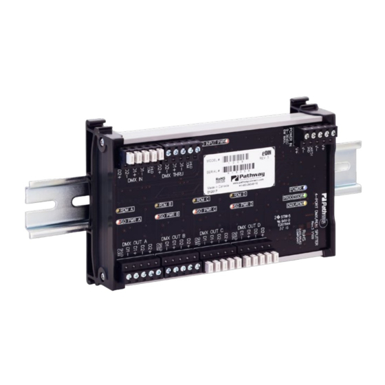
DMX Interface - PWREP DIN P4 RDM
4-Way DMX/RDM Repeater
OVERVIEW
The Pathway DIN-mount DMX/RDM Splitter supports the bi-
directional communications necessary for E1.20 Remote
Device Management in DMX512 installations requiring star-
wiring.
Full opto-isolation between all ports adds maximum
protection against common mode voltages or ground faults
for connected equipment.
CONNECTIONS
The PWREP DIN P4 RDM features terminal strips that can be removed
from the card to facilitate easy wiring installation or replacement. Make
the following connections, WITH THE POWER TURNED OFF, and
observe ESD precautions by ensuring the installer is properly grounded
before handling the device.
POWER
The DMX/RDM Splitter is designed to run on a range of voltages from
9-30 volts DC. Each DMX/RDM Splitter requires 6 watts. Observe the
correct polarity when connecting to V+ and V-.
A second set of terminals are provided as a DC power-through
connection to other DIN devices. The EARTH GND terminal may be
connected to the enclosure's chassis or electrical ground terminal to
improve EMC compliance.
DMX512
DMX connections consist of a shield and a data pair. An optional second
auxiliary data pair is also occasionally employed. DMX IN usually comes
from a control console, Pathport® Gateway, architectural controller or
opto-splitter. DMX THRU provides a means to daisy-chain DMX to other
DIN devices.
Connect DATA+ and DATA- to D1+ and D1– on the DMX IN terminal.
Connect the cable shield or common to the SHLD COM terminal.
Observe the same polarity convention throughout the system while
connecting the four outputs.
Connect wires for DATA2+ and DATA2– to D2+ and D2–, if desired. It
is not necessary to connect these wires for DMX or RDM to function.
other DIN devices
in same enclosure
DMX In from
Control System
Isolated DMX512
Outputs to devices
(x4)
DMX Thru to
ISO INPUT PWR
DMX IN
DMX THRU
RDM A
RDM B
RDM C
RDM D
ISO PWR A
ISO PWR B
ISO PWR C
ISO PWR D
DMX OUT B
DMX OUT B
DMX OUT C
6.25"
[159mm]
STATUS INDICATORS
POWER IN
PROCESSOR
DMX INPUT
ISO POWER IN Red. Internally isolated power supply for input
ISO POWER
A/B/C/D
RDM A/B/C/D
RDM CONTROLLER
A compliant RDM controller must be used to get and set RDM information
and commands. The PWREP DIN P4 RDM does not provide controller
functions, but simply allows RDM messages within a star-wiring network.
A Pathport Gateway and suitable software can be used to provide RDM
controller functions.
Power In:
9-36VvDC, 6W Supply required.
Use PWPWR DIN TERM 50W 24VDC
Connect Earth ground to to improve
EMC compliance
Status LEDs
4.0"
POWER
[103mm]
PROCESSOR
DMX/RDM
DMX OUT D
Blue. Glowing steadily indicates power supply OK;
off indicates no power.
Green. Glowing steadily indicates processor is
OK; off when POWER IN is lit indicates processor
failure.
Amber. Glowing steadily indicates data signal
received; off indicates no signal present.
processing working correctly. Off indicates no
power.
Red. Internally isolated power supply to that output
port is working correctly. Off means no power to
that port.
Amber. Flickering indicates presence of RDM
data packets. Off indicates no RDM activity on the
network.
Fastening mechanism
designed for 35 X 7.5mm
DIN rail release lever
Use large flat-head screwdriver or
similar tool to gently pry lever
away from DIN rail to release
1.85"
[47mm]
Manual
DIN rail
08/30/21
Advertisement
Table of Contents

Related Manuals for pathway PWREP


Summary of Contents for pathway PWREP
- Page 1 STATUS INDICATORS POWER IN Blue. Glowing steadily indicates power supply OK; The PWREP DIN P4 RDM features terminal strips that can be removed off indicates no power. from the card to facilitate easy wiring installation or replacement. Make the following connections, WITH THE POWER TURNED OFF, and PROCESSOR Green.
- Page 2 • Operating Conditions: 14°F-113°F (-10°C to 45°C); 5-95% relative humidity, non-condensing © 2021 Acuity Brands, Inc. • One Lithonia Way, Conyers GA 30012 Pathway Connectivity | #103 - 1439 17th Ave SE Calgary, AB Canada T2G 1J9 Phone: + 1 866 617 3074 www.pathwayconnect.com 08/30/21...
Need help?
Do you have a question about the PWREP and is the answer not in the manual?
Questions and answers