Advertisement
Quick Links
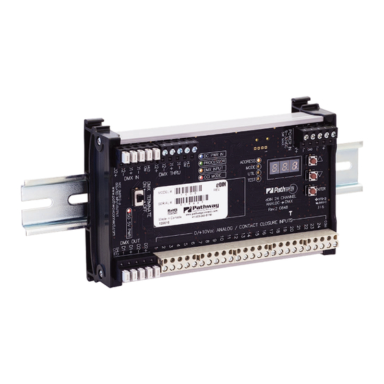
OVERVIEW
The 1006 Analog to DMX interface provides the ability to
convert analog 0-10VDC signals to DMX512 protocol. The
analog inputs may also be used as dry contact inputs, either
triggering a DMX channel to full, or to recall up to 24 presets.
The DMX input may be merged with the analog input signal or
with the preset recall. The DIN form factor makes installation
in your own enclosures or cabinets fast and easy.
The module is RDM discoverable and configurable.
CONNECTIONS
The 1006 features terminal strips that can be removed from the
card to facilitate easy wiring installation or replacement. Make the
following connections, WITH THE POWER TURNED OFF.
POWER
The module will run on a range from 9 to 30 VDC at a maximum
of 5 Watts. Observe the correct polarity when connecting the V+
and V-. A second set of terminals are provided on the connector to
daisy-chain power to other eDIN modules. The EARTH GROUND
terminal must be connected to the enclosure's chassis or electrical
ground terminal to ensure EMC compliance.
DMX512
DMX connections consist of a shield and data pair. Connect the
DATA+ and DATA- wires to D1+ and D1- respectively for each of
DMX IN, DMX OUT and DMX THRU (if applicable). Observe the
same polarity convention throughout the system. Connect the cable
shield to the SHLD COM terminal.
DMX OUT is the processed output of the interface. DMX IN is
optional; DMX input will be merged with the analog inputs or used
as a source of levels when recording presets.
DMX THRU may be daisy-chained to the DMX IN of other eDIN
modules.
END OF LINE
TERMINATION SWITCH
DMX OUTPUT
1006-200-REV1
TM
Model 1006 24-Channel
Analog to DMX
DMX IN FROM
CONTROL SYSTEM
DMX THRU TO
OTHER eDIN MODULES
DMX OUT
24 ANALOG / CONTACT CLOSURE INPUTS
(10VDC MAX ANALOG MODE;
NO VOLTAGE ALLOWED IN
CONTACT CLOSURE MODE
STATUS INDICATORS
POWER IN
PROCESSOR Green. Steady glow indicates processor is OK;
DMX INPUT
CCI MODE
FUNCTION
ANALOG / CONTACT CLOSURE INPUTS
The 1006 supports 24 discrete inputs that can be configured as
either analog or contact closure inputs. The COM (common) terminal
must be used as a signal reference, regardless of input configuration.
Analog inputs must be 0 to +10 VDC with respect to COM. Contact
inputs are simply maintained or momentary dry contact closures
between COM and the individual input.
MENU FUNCTION
LEDs
STATUS LEDs
DC POWER IN
PROCESSOR
ADDRESS
DMX INPUT
MODE
CCI MODE
UTIL
TEST
eDIN 24 CHANNEL
ANALOG
DMX
PROGRAM
PUSHBUTTONS
LED NUMERIC
DISPLAY
Manual
Blue. Steady glow indicates power supply OK;
off indicates no power.
off when POWER IN is lit indicates processor
failure.
Amber. Steady glow indicates port latched
to active DMX source; off indicates no signal
present.
Red. Steady glow indicates contact closure input
mode is active.
Amber. Indicates the function associated with
the numeric display.
POWER IN:
9-30VDC, 5W SUPPLY REQUIRED
USE #1001-100-24-DIN POWER SUPPLY
OR EQUAL.
CONNECT EARTH GROUND TO PROTECT
DMX INPUT FROM RF INTERFERENCE
CARRIED ON CABLE SHIELD.
EARTH
GND
ENTER
04/25/19
Advertisement

Related Manuals for pathway eDIN 1006


Summary of Contents for pathway eDIN 1006
- Page 1 Model 1006 24-Channel Manual Analog to DMX OVERVIEW The 1006 Analog to DMX interface provides the ability to convert analog 0-10VDC signals to DMX512 protocol. The analog inputs may also be used as dry contact inputs, either triggering a DMX channel to full, or to recall up to 24 presets. The DMX input may be merged with the analog input signal or with the preset recall.
- Page 2 OFF and termination be applied to the final device in the daisy-chain. levels will determine the DMX512 output levels, and all recalled presets will be ignored. support@pathwayconnect.com Pathway Connectivity Solutions #103—1439 17Avenue SE Calgary AB www.pathwayconnect.com Canada T2G 1J9 tel (403) 243-8110 fax (403) 287-1281...
- Page 3 • ANSI E1.11 DMX512-A(2008)/USITT DMX512(1990) • ANSI E1.20 RDM(2010) - Remote Device Management • ANSI E1.3 0-10V Analog Control • RoHS 2011/65/EU • CE support@pathwayconnect.com Pathway Connectivity Solutions #103—1439 17Avenue SE Calgary AB www.pathwayconnect.com Canada T2G 1J9 tel (403) 243-8110 fax (403) 287-1281 1006-200-REV1...
Need help?
Do you have a question about the eDIN 1006 and is the answer not in the manual?
Questions and answers