Table of Contents
Advertisement
Quick Links
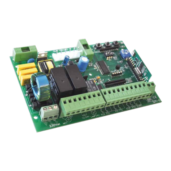
Q71S 230V Control Board
Sliding Gate – MyRoller 15
TECHNICAL FEATURES
Control Panel Dimensions
Control Panel Weight
On-Board Transformer
Flashing light Power Supply
Obstacle Detection Level
Programming Procedure
Deceleration Time
Pause Time
The MyGate Q71S Control Board Installation Manual : Printed 11/02/2013 13:16
Instruction Guide
-
140 x 95 x 38mm
-
0.186Kg
30VA 230/0 – 12 /24Vac
-
-
24Vdc, MAX 20W
-
Automatic
-
Streamline
-
Adjustable
-
Adjustable
1
Advertisement
Table of Contents

Related Manuals for MyGate Q71S

Summary of Contents for MyGate Q71S
- Page 1 Control Panel Weight 0.186Kg 30VA 230/0 – 12 /24Vac On-Board Transformer Flashing light Power Supply 24Vdc, MAX 20W Obstacle Detection Level Automatic Programming Procedure Streamline Deceleration Time Adjustable Pause Time Adjustable The MyGate Q71S Control Board Installation Manual : Printed 11/02/2013 13:16...
-
Page 2: Table Of Contents
Adjusting Obstacle Detection Sensitivity during the Deceleration Phase of the Opening / Closing Cycle ................................18 Appendix: A ............................21 Q71S connection map – terminals 1 to 21 ................... 21 Q71S control board – FAQ’S ....................... 22 Comments & Feedback ........................... 26 The MyGate Q71S Control Board Installation Manual : Printed 11/02/2013 13:16... -
Page 3: Q71S Control Board Layout
Q71S control board layout Map of Q71S The MyGate Q71S Control Board Installation Manual : Printed 11/02/2013 13:16... -
Page 4: Pre-Installation Checks
Pre-installation checks Thank you for choosing Gate Motors MyGate product for your gate automation needs. This instruction booklet accompanies every swing gate automation model that uses the Q71S control board. This control board tells the motors what to do and how to behave. The control board has memory chips onboard which store the key-fob transmitting codes and the parameters the motors will be working to. -
Page 5: Linking Essential Terminals
“thinks” you have pressed a STOP button and, of course, will halt all operations – regardless to any command you may give it. Be sure to tighten the terminals screws to ensure good contact is made. The MyGate Q71S Control Board Installation Manual : Printed 11/02/2013 13:16... -
Page 6: Connecting The Motors To The Control Board
These are Brown and Black. Please swap as illustrated below: The MyGate Q71S Control Board Installation Manual : Printed 11/02/2013 13:16... -
Page 7: Photocells
Photocells The MyGate photocells are essential for safe use of your gate automation system. These are units that are comprised of a transmitter and receiver. The photocell transmitter projects an Infrared confined beam in a straight line and is intercepted by the photocell receiver. The receiver is not a mirrored unit as it absorbs the Infrared beam. -
Page 8: Photocell Wiring
/ pedestrian moves through the closing gates and breaks the Infrared beam – the gates will immediately stop and reverse to the closed position at great speed. The MyGate Q71S Control Board Installation Manual : Printed 11/02/2013 13:16... -
Page 9: To Use In Closing Cycle
Use 1 core wire to connect 4th terminal (looking from left to right) on photocell Receiver Unit (RX) to Terminal 16 IMPORTANT: Please place a link between terminals 14 and 15 The MyGate Q71S Control Board Installation Manual : Printed 11/02/2013 13:16... - Page 10 We can now introduce power to the control board so we can enable the programming of the key-fobs and the programming of the gate automation opening and closing settings. The MyGate Q71S Control Board Installation Manual : Printed 11/02/2013 13:16...
-
Page 11: Connecting Power To The Control Board
If an emergency stop button is not fitted, a link must be placed between terminals 18 + 21 Now we look to program the remote control key-fob(s) to the control board. The MyGate Q71S Control Board Installation Manual : Printed 11/02/2013 13:16... -
Page 12: Programming The Remote Control / Key-Fob
Deleting existing remote controls / key-fobs from the control board a) Press and hold the P1 button, the DL1 light will come on. Keep the button pressed until the DL1 light goes off. The MyGate Q71S Control Board Installation Manual : Printed 11/02/2013 13:16... -
Page 13: Changing The Code The Key-Fob Transmits
Once this has been completed you must program the key-fob to the control board so it can recognise the new code generated. The MyGate Q71S Control Board Installation Manual : Printed 11/02/2013 13:16... -
Page 14: Remote Control Receiver
If you find the range your radio receiver is having trouble with the interception of your key-fobs transmitting frequency and code, a MyGate Extended Aerial can be fitted to your receiver unit. Extended Aerial – (optional accessory) -
Page 15: Selecting The Operating Mode
If a START command is given while the gate is closing, the gate STOPS and REVERSES in about 1.5 seconds. To select this operating mode place the DS1 dip-switches as shown right: 1=OFF 2=ON 3=OFF The MyGate Q71S Control Board Installation Manual : Printed 11/02/2013 13:16... -
Page 16: Programming The Gates Open & Closing Cycles
During the first 8 seconds of the opening cycle, the motor is travelling slowly. This is the control board calculating the ‘deceleration speed’ required for the motor. Use the RV1 adjuster The MyGate Q71S Control Board Installation Manual : Printed 11/02/2013 13:16... -
Page 17: Setting The Pause Time
Obstacle Detection The Q71S features built-in obstacle detection during opening and closing cycles. This feature is present during the whole gates operation and cannot be turned off. The control board automatically adjusts the detection sensibility according to the force required to the motor to physically move the gate. The obstacle detection operates by measuring the force required to move the weight of the gate and detects resistance if the gate becomes obstructed. -
Page 18: Adjusting Obstacle Detection Sensitivity During Normal Opening / Closing Cycle
This is caused by the gate “bouncing” off the gate stops (physical ground stops) and the control board detects this as a potential obstacle. The MyGate Q71S Control Board Installation Manual : Printed 11/02/2013 13:16... - Page 19 “a)” paying particular attention to the position of the RV1 trimmer for the torque setting. Adjust this trimmer switch to a lower position. The motors may be providing more push and pull power than they need to be for the weight of your gate. The MyGate Q71S Control Board Installation Manual : Printed 11/02/2013 13:16...
- Page 20 The opening & closing cycles have been programmed The opening & closing cycle has been tested The Obstacle detection level / setting has been tested Your installation is now complete! The MyGate Q71S Control Board Installation Manual : Printed 11/02/2013 13:16...
-
Page 21: Q71S Connection Map - Terminals 1 To 21
Q71S connection map – terminals 1 to 21 Map showing connections for: Motor 1 (Included with Kit) Safety Photocells (Included with Kit) Flashing light (Optional Accessory) Extended Aerial (Optional Accessory) The MyGate Q71S Control Board Installation Manual : Printed 11/02/2013 13:16... -
Page 22: Q71S Control Board - Faq's
Weather condition - As the key-fob remotes function by transmitting a radio frequency signal to the control board, signal quality can be diminished as a result of poor weather; rain, fog and in some cases electrical The MyGate Q71S Control Board Installation Manual : Printed 11/02/2013 13:16... - Page 23 In order for these devices to work with the MyKey key-fob remotes, each device will need an additional radio receiver. The MyGate Q71S Control Board Installation Manual : Printed 11/02/2013 13:16...
- Page 24 Your intercom should have 2 sets of outputs for unlocking MAG locks (labeled as C – Common & N/C - Normally Closed) and for switching volt free contact equipment (labeled as C – Common, N/O - Normally Open). To connect the intercom to the Q71S control board for opening the gate from your intercom handset:...
- Page 25 Following practical maintenance will ensure continued uninterrupted automation service. The MyGate Q71S Control Board Installation Manual : Printed 11/02/2013 13:16...
-
Page 26: Comments & Feedback
Trading address: GateMotors UK, Unit 16c, Chalwyn Industrial Estate, St. Clements Road, Poole, Dorset. BH12 4PE. GateMotors is the trading name of Screwjack Limited - registered office at 21 Oxford Road, Bournemouth, Dorset. BH8 8ET. Registered # is 4287804, VAT #:785 3450 06 The MyGate Q71S Control Board Installation Manual : Printed 11/02/2013 13:16...
Need help?
Do you have a question about the Q71S and is the answer not in the manual?
Questions and answers