Advertisement
Installation Manual: PAD100-LED LED Module
NOTICE TO THE INSTALLER
This manual provides an overview and the installation instructions for the PAD100-LED module. This module is only compatible
with addressable fire systems that utilize the PAD Addressable Protocol.
All terminals are power limited and should be wired in accordance with the requirements of NFPA 70 (NEC) and NFPA 72 (National
Fire Alarm Code). Failure to follow the wiring diagrams in the following pages will cause the system to not operate as intended. For
further information, refer to the control panel installation instructions.
The module shall only be installed with listed control panels. Refer to the control panel installation manual for proper system
operation.
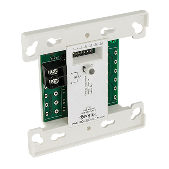
1. Description
The PAD100-LED module uses one (1) SLC loop address when used as an addressable indicator. The PAD100-LED is an
addressable LED module used to provide indication of a variety of system conditions. The module mounts on either an UL Listed
2-1/2" deep 2-gang box or 1-1/2" deep 4" square box.
The PAD100-LED includes one red LED to indicate the module's status. In normal condition, the LED flashes when the device is
being polled by the control panel. When activated, the LED will flash at a fast rate.
2. Setting the Address
All PAD protocol detectors and modules require an address prior to connection to the panel's SLC loop. Each PAD device's
address (i.e., detector and/or module) is set by changing the dip switches located on the device. PAD device addresses are
comprised of a seven (7) position dip switch used to program each device with an address ranging from 1–127.
Figure 1. PAD Device Dip Switch Addresses Table (Addresses 1–127)
1
2
4
8 16 32 64
1
27
2
28
3
29
4
30
5
31
6
32
7
33
8
34
9
35
10
36
11
37
12
38
13
39
14
40
15
41
16
42
17
43
18
44
19
45
20
46
21
47
22
48
23
49
24
50
25
51
26
52
1
2
4
8 16 32 64
Note: Each "gray" box indicates that the dip switch is "On," and each "white" box indicates "Off."
The examples shown below illustrate a PAD device's dip switch settings: the 1st example shows a device not addressed where all
dip switch settings are in the default "Off" position, the 2nd illustrates an addressed PAD device via the dip switch settings.
Figure 2. Examples of PAD Device Showing Default Dip Switch Setting (Unaddressed) & Addressed PAD Device
1 2 4
8
16
32 64
On
Off
Potter Electric Signal Company, LLC
1
2
4
8 16 32 64
1
2
53
54
55
56
57
58
59
60
61
62
63
64
65
66
67
68
69
70
71
72
73
74
75
76
77
1
2
1
2
4
8 16 32 64
All dip switches are
shown in the "Off"
position.
•
St. Louis, MO
Document 5406312-A 02/16
firealarmresources.com
4
8 16 32 64
1
2
4
8 16 32 64
78
79
80
81
82
83
84
85
86
87
88
89
90
91
92
93
94
95
96
97
98
99
100
101
102
4
8 16 32 64
1
2
4
8 16 32 64
1 2 4
8
16
32 64
On
Off
•
Phone: (800) 325-3936
1
2
4
8 16 32 64
103
104
105
106
107
108
109
110
111
112
113
114
115
116
117
118
119
120
121
122
123
124
125
126
127
1
2
4
8 16 32 64
Example shows this PAD device's
address = 42. Dip switches #2, 8 &
32 are in the "On" position.
•
www.pottersignal.com
PAGE 1 OF 2
Advertisement
Table of Contents

Subscribe to Our Youtube Channel
Related Manuals for Potter PAD100-LED


Summary of Contents for Potter PAD100-LED
- Page 1 2-1/2" deep 2-gang box or 1-1/2" deep 4" square box. The PAD100-LED includes one red LED to indicate the module's status. In normal condition, the LED flashes when the device is being polled by the control panel. When activated, the LED will flash at a fast rate.
- Page 2 0.6 lbs 4. Wiring Diagrams The wiring diagram shown below illustrates how to wire a PAD100-LED module. Additionally, an installation diagram shows how to install the module using a compatible electrical box. Figure 3. Examples of Installing a PAD100-LED Using a Compatible Electrical Box & Wiring a PAD100-LED...
Need help?
Do you have a question about the PAD100-LED and is the answer not in the manual?
Questions and answers