
Related Manuals for PowerGrip YG-3

Summary of Contents for PowerGrip YG-3
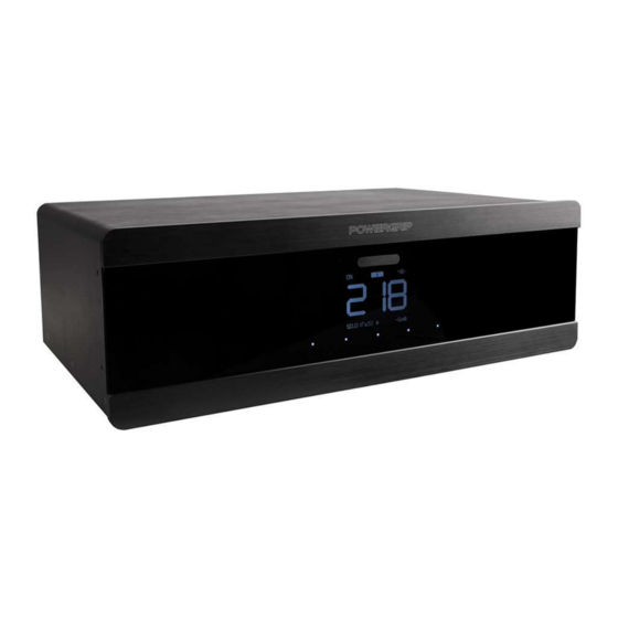
- Page 1 Clean Power Console POWERGRIP YG-3 Clean Power and Smart Protection for your A/V system...
-
Page 2: Warranty
Dear customer, thank you for purchasing the POWERGRIP YG-3 Clean Power Console. You have purchased a power unit with excellent filtering quality, a high level of protection and rich control functionality. Before you start using the console, we strongly recommend that you read this manual through to the end. This information will allow you to fully use all the features of the power console and increase the performance of your system. -
Page 3: Safety Instructions
Safety Instructions • Connect the POWERGRIP Console directly to a stationary grounded power outlet. Do not connect with an extension cord, power distribution unit, UPS, protection device or voltage stabilizer unless approved by the manufacturer. • Do not expose the unit to moisture. Use indoors only. - Page 4 FRONT PANEL 1. Main Power On/Off hardware switch (located underneath the unit I/O). 2. Touch sensor: Short press starts sequential power on/off of the sockets. Long press to enter Menu. To disable demonstration mode enter Menu --> Display --> Choose style. 3.
- Page 5 7. GENERAL FILTER section. Sockets for other types of equipment. 8. Ethernet terminal – optional extra. Contact POWERGRIP dealer to purchase. 9. Trigger input for control by 3rd party devices. Can operate as RS232 input (see www.powergrip.com for more information). Output is to control 3rd party devices.
-
Page 6: Settings Menu
‘always ON’. <Amb.Light> -Activation with illumination of YG-3. The Threshold can be set in the ‘Display’ section of menu. ‘OFF Threshold’ controls the level of activation. In case the display is set to auto option, when the display is turned off/on this function will trigger as well. - Page 7 Display: Brightness -Display Brightness level. Auto -automatic brightness by light sensor. Аuto2 -same with less light to brightness response. 0...10 -static value. OFF Threshold -illumination level (conventional units) at which display turns on in auto mode. This setting also controls turn on by brightness function. 0...18 -more value needs more illumination to turn on display.
- Page 8 ‘always ON’. <Amb.Light> -Activation with illumination of YG-3. The Threshold can be set in the ‘Display’ section of menu. ‘OFF Threshold’ controls the level of activation. In case the display is set to auto option, when the display is turned off/on this function will trigger as well.
- Page 9 9) change button name in the App according to the function Wi-Fi status -status of Wi-Fi connection. Link Ch1..4 to -the App has 4 control buttons. Those can be assigned to sensor buttons of the YG-3. <Sens.btn1> -Link to sensor button 1 (enumeration from left to right) <Sens.btn2>...
- Page 10 Control: Group 1 current: -Current drain from group 1. Group 1 must be on to let this function work. go to commutation menu to set it. On threshold -The amount of current to turn on assigned function. < I Group1> must be assigned to any function in commutation or sequencer menus.
- Page 11 Display 1) Mains voltage sine wave cut in percent - represent the load of the building mains cables. 4% or more - poor wires or wires overload. 6% or more - a critical wiring condition. 2) Sequencer on state indicator - Appears after Sequencer was started and next button press will lunch sequencer turn off sequence.
- Page 12 5) Filter mode. See filtering section of this manual. - filter + dumper. - filter 6) Grounding indicator. Appears in case of grounded console connection. If "!" is shown it means that there is critical connection issue. Please refer that console is connected according to connection diagram (13). 7) DC filter state.
- Page 13 Filtering Hi-Fi High Current filter section: This is designed for Hi-Fi devices and high-power amplifiers and features a special design with low output impedance to reduce device to device interference. Wide cooper traces provide current to amplifiers without limitation. Because the filter construction avoids any resonances this filter can do filtering in the audio range without adding distortion and additional noise.
- Page 14 If grounding doesn’t exist, or the power line does not comply with TN standard this function is not available. In this case you need to connect YG-3 as shown on diagram 13 by using a phase detecting tool. Antenna grounding connector In case an antenna is used in your system it is important to use the supplied antenna grounding cable.
-
Page 15: Specification
Specification: 1) Voltage range for safe continuous operation of YG-3 PSU: 160-320 V. 2) Protection voltage range (turn off connected devices): low - 190V, high - 256V. (May be influenced by other parameters like mains distortion to provide best protection and exclude false... - Page 16 High current Hi-Fi Plot: Filtering from mains to devices. Differential mode: RED - Filter option in off state. Yellow - Filter option in on state. Dumper is off. Green - Filter option in on state. Dumper is on. General filter plot: Filtering from devices to mains.
-
Page 17: Block Diagram
Block diagram: mains input Fuse Main relay MOV protection and protection filtering Series filter "General Filter" bypass DC filter Provide filtering in both directions. relay Relay Relay Current group 3 group 2 sensor Parallel configurable filter "High current Hi-Fi Filter" Socket Socket Socket... - Page 18 www.powergrip.com...
Need help?
Do you have a question about the YG-3 and is the answer not in the manual?
Questions and answers