Table of Contents
Advertisement
Quick Links
Advertisement
Table of Contents

Related Manuals for Lencore G1505


Summary of Contents for Lencore G1505
- Page 1 USER MANUAL MPI-2 LOCAL RACK UNIT (Model G1505) Rev C...
-
Page 2: Table Of Contents
MPI-2 Local Rack Unit Contents MPI-2 Local Rack Unit ....................... 1 Overview ............................2 Features and Capabilities ........................ 2 Inputs ............................2 Output ............................2 LEDs ............................. 2 Front Panel ............................3 Rear View ............................4 Wiring .............................. 5 To Global MPI ..........................5 Microphone Input........................ - Page 3 Adding a Global MPI-2....................... 16 Overview The Local MPI-2 rack unit is Lencore’s music and page interface (MPI) to be used for i.Net systems. The MPI-2 is capable of zoned or all-call paging as well as background music. Paging can be made via any telephone on the network or a microphone.
- Page 4 IMPORTANT SAFETY INSTRUCTIONS RISK OF ELECTRIC SHOCK- DO NOT OPEN THE UNIT. THERE ARE NO SERVICABLE COMPONENTS INSIDE. Read these instructions. Keep these instructions. Heed all warnings. Follow all instructions. Do not use this apparatus near water. Clean only with dry cloth. Do not block any ventilation openings.
-
Page 5: Mpi-2 Local Rack Unit
MPI-2 Rack Unit Lencore’s Music Page Interface (MPI) Rack Unit replaces all the bulky headend equipment that is associated with music and paging systems. With the MPI, there is no need for additional cable home runs, amplifiers, separate equalizers, special switching equipment or matching vendors for compatible product interfaces. -
Page 6: Overview
Features and Capabilities • Front panel LEDs. Various front panel LEDs indicate various functions and activity of the unit. • Analog phone input. • Built-in speaker for testing/troubleshooting. • Audio Test button. The Audio Test button is used to play pre-recorded music for testing/troubleshooting the paging lines. -
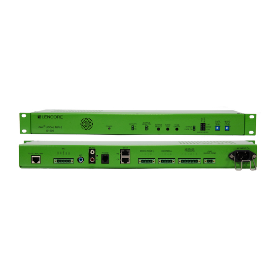
Page 7: Front Panel
Front Panel 1. Power LED 6. Page On/Off The power LED indicates power to the Used to start and stop a page for audio unit. connected to the MIC input. 2. Activity LEDs 7. Status/Page On LEDs The activity LEDs indicate LON activity. The Status LED will flash while the unit is booting up and on when a page is 3. -
Page 8: Rear View
Rear View 11. To Global MPI 17. Break Tones Connect an RJ45 cable to the optional The break tones input is used to trigger Global MPI. break tones. 12. MIC 18. Doorbell The 5-position MIC input is for a The doorbell input is used to trigger microphone input. -
Page 9: Wiring
Wiring To Global MPI The addition of a Global MPI-2 is optional. The Global MPI-2 allows the user to page all buildings with a Global MPI-2 simultaneously. The “To Global” MPI connector is for communicating to the Global MPI. Wire the “TO GLOBAL MPI” to the Global MPI’s “TO LOCAL MPI”... -
Page 10: Microphone Rca Input
Microphone RCA Input The Microphone RCA input allows a line-level microphone input to be used for paging. Connect a line-level microphone signal to the MIC RCA connector using an RCA cable. Music Input The Music input is for background music. Connect a line-level music source to the MUSIC input using an RCA cable. -
Page 11: Data
Data The Data connector is used for communicating to the head-end and to the OP. Connect the “HE” to the head-end “TO OP” connector using an RJ45 cable. Connect the “OP” to the OP Data In connector using an RJ45 cable. PINS - 568 B ORANGE|WHITE ORANGE... -
Page 12: Doorbell
Doorbell The Doorbell input connector is used to trigger one of two doorbell chimes. Connect a normally open dry contact to “1” and “C1” for doorbell chime #1 and/ or “2” and “C2” for doorbell chime #2 using 16 AWG wire. The doorbells are all-call only. -
Page 13: Gnd (Audio Com)
GND (Audio Com) The GND (Audio Com) connector is the audio return for the system. Connect a single 16 AWG wire from the GND (Audio Com) to the head-end GND and to the OP GND (Audio Com). AC Input Connect the supplied IEC power cord to the AC Input. The unit is rated at 100-240VAC. -
Page 14: Activity
Activity The activity LEDs indicate LON activity. The LEDs will be flickering under normal activity. LON is the communication protocol for the i.Net system. Source Selected The Source Selected LEDs indicate which source (5 for music, 6 for paging) has been selected to be played through the internal speaker. -
Page 15: Audio Test Pushbutton
Audio Test Push Button The audio test push button is used to play a pre-recorded music clip over the paging lines. This is used for testing and troubleshooting purposes. Press the Audio Test button one and the Status LED will blink while a pre-recorded sound clip plays over the speakers using the paging lines. -
Page 16: Audio Level (Page/Music) Leds
Audio Level (Page/Music) LEDs The Audio Level LEDs indicate the audio level input for the paging and music signals. Low (yellow) indicates a low audio level, Good (green) indicates a good audio level, and Clip (red) indicates an audio level that is too high, and clipping is occurring. -
Page 17: Input Music Volume Potentiometer
Input Music Volume Potentiometer The Input Music Volume potentiometer allows the music input to be adjusted to maintain a good music level indicated by a green LED for the Audio level LEDs. Adjustments can be made by a small flat blade screwdriver. The potentiometer is a single-turn potentiometer. -
Page 18: Operation
4. Wait for a tone from the MPI then make the page. Hang up the phone receiver when the page is complete. The Status LED will turn off. Note: The zones must be configured with Lencore’s System Manager software. The telephone input requires a POTS appearance line using an RJ11 connector. -
Page 19: Direct Mic Connection
3. Release the MIC key when the page is complete. Microphone RCA connection 1. Connect a MIC to Lencore’s MIC pre-amplifier (sold seperately). 2. Connect the audio output of the MIC pre-amp to the MIC RCA audio input of the MPI-2. -
Page 20: Internal Speaker Source Select
Internal Speaker Source Select: The push button selector switch can select the audio source to play over the internal speaker. Press the push button until the Source Selected LED indicates the source to play over the internal speaker. Source 5 is the paging line and source 6 is the music line. - Page 21 Lencore Acoustics LLC 516-682-9292 info@lencore.com www.lencore.com The information contained herein is proprietary to Lencore Acoustics LLC and copyright protected. No part of this manual © can be copied, used or distributed without prior authorization from Lencore Acoustics Corp. Copyright 2021...
Need help?
Do you have a question about the G1505 and is the answer not in the manual?
Questions and answers