Table of Contents
Advertisement
Quick Links
Advertisement
Table of Contents

Related Manuals for Lencore MPI-2 GLOBAL RACK UNIT


Summary of Contents for Lencore MPI-2 GLOBAL RACK UNIT
- Page 1 USER MANUAL MPI-2 GLOBAL RACK UNIT Document Number: 200-0018 Rev A...
-
Page 2: Table Of Contents
MPI-2 Global Rack Unit Contents MPI-2 Global Rack Unit ......................1 Overview ............................2 Features and Capabilities ........................ 2 Inputs ............................2 Outputs ............................2 LEDs ............................. 2 Front Panel ............................4 Rear View ............................5 Wiring .............................. 6 To Local MPI ..........................6 Microphone Input........................ -
Page 3: Overview
Overview The Global MPI-2 rack unit is Lencore’s auxiliary page interface (MPI) to be used for iNET systems. The Global MPI-2 is designed to make a global all-call page to every building that has a Global MPI-2. Paging can be made via any telephone on the network or a microphone. -
Page 4: Leds
LEDs • Power – solid when the unit is powered. • Activity - Rx – blinks when Neuron is receiving data Tx – blinks when Neuron is transmitting data. • Status – blinks every 8 seconds and solid when paging. Solid when an IR remote button is pressed. -
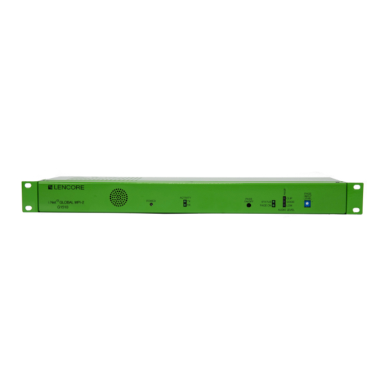
Page 5: Front Panel
Front Panel 1. Power LED The power LED indicates power to the unit. 2. Activity LEDs The activity LEDs indicate LON activity. 3. Page On/Off Used to start and stop a page for audio connected to the MIC input. 4. Status/Page On LEDs The status LED will flash every few seconds to indicate that the internal processor is operating. -
Page 6: Rear View
Rear View 7. To Local MPI Connect an RJ45 cable to the Local MPI-2. 8. Mic Input 1 The 5-position MIC input is for a microphone input. 9. PTT for Mic input 2 Input for MIC PTT key switch. 10. Mic Input 2 Mic Line Level Input. -
Page 7: Wiring
Wiring To Local MPI The “To Local” MPI connector is for communicating to the Local MPI. Wire the “TO LOCAL MPI” to the Local MPI’s “TO GLOBAL MPI” connector using an RJ45 cable. The Global MPI-2 cannot operate without the Local MPI-2. Microphone Input The microphone input is for a dynamic microphone. -
Page 8: Microphone Rca Input
Microphone RCA Input The Microphone RCA input allows a line-level microphone input to be used for paging. Connect a line-level microphone signal to the MIC RCA connector using an RCA cable. Mic PTT Input MIC PTT The MIC PTT input is for the microphone’s PTT switch. Wire the MIC PTT wires to this input (polarity independent). -
Page 9: Gnd (Audio Com)
GND (Audio Com) The GND (Audio Com) connector is the audio return for the system. Connect a single 16 AWG conductor from the Global MPI-2 GND (Audio Com) to the Local MPI-2 GND. AC Input Connect the supplied IEC power cord to the AC Input. The unit is rated ate 100- 240VAC. -
Page 10: Activity
Activity The activity LEDs indicate LON activity. The LEDs will be flickering under normal activity. LON is the communication protocol for the iNET system. Page On/Off pushbutton The page on/off pushbutton is used to toggle the page on and off command. This is used for testing and troubleshooting purposes. -
Page 11: Status/Page On Leds
Status/Page On LEDs The Status LED indicates that the internal microprocessor is functioning normally. The Page On LED indicates an active page is in progress. Audio Level (Page/Music) LEDs The Audio Level LEDs indicate the audio level input for the paging signal. Low (yellow) indicates a low audio level, Good (green) indicates a good audio level, and Clip (red) indicates am audio level that is too high, and clipping is occurring. -
Page 12: Operation
Operation Plug the power adapter into the Global MPI-2. The Power LED will be on and solid while the Status LED will blink for approximately 10 seconds. When the Status LED stays off, the MPI-2 is ready to use. Assure that the Local MPI-2 is also in a ready state. -
Page 13: Microphone Rca Connection
Microphone RCA connection 1. Connect a microphone to Lencore’s MICq pre-amplifier. 2. Connect the audio output of the MIC pre-amp to the MIC RCA audio input of the MPI-2. 3. Press the MIC key and make the page. The page input can be adjusted for the proper level by turning the Page potentiometer CW or CCW. - Page 14 Lencore Acoustics LLC 516-682-9292 info@lencore.com www.lencore.com The information contained herein is proprietary to Lencore Acoustics LLC and copyright protected. No part of this manual © can be copied, used or distributed without prior authorization from Lencore Acoustics Corp. Copyright 2021...
Need help?
Do you have a question about the MPI-2 GLOBAL RACK UNIT and is the answer not in the manual?
Questions and answers