
Related Manuals for Genave RXC-3000

Summary of Contents for Genave RXC-3000
- Page 1 ™ RXC-3000 USB / Twist-n-Touch™ Receiver Decoder Controller Hardware Manual Genave / NRC, Inc. www.genave.com support@genave.com Copyright 2017. Genave / NRC, Inc. Tech. Publication No. 9000-0000-040 Rev 10...
- Page 2 RXC-3000 Hardware Installation and User Guide Warning If incorrectly used, this equipment can cause severe injury. Those who use and maintain the equipment should be trained in its proper use, warned of its dangers, and should read the manuals before attempting ...
- Page 3 RXC-3000 Hardware Installation and User Guide Important Safety Information Installation & Service Precautions Electrocution, severe personal injury and damage to equipment can occur during installation or servicing this equipment. All electrical work should be performed by, or under the supervision of an experienced electrician and in accordance with all applicable electrical, fire, building and safety codes.
- Page 4 (including damages for loss of business profits, business interruption, loss of business information, and the like) arising out of the use or inability to use the software or hardware even if the Genave and/or its licensor has been advised of the possibility of such damages.
-
Page 5: Table Of Contents
Restoring RXC-3000 to Default Programming ................18 Inputs............................... 19 Input Header Characteristics (J14 and J15) ..................19 Triggering RXC-3000 From an Input..................... 20 (Example) Interfacing RXC-3000 To External Switches ............... 21 Outputs ..............................22 Relay Characteristics ........................22 Output Header Pinout (Aux Output)(J5) ..................23 Pin 1 - Relay #1 ........................... - Page 6 Real Time Clock Battery ........................ 35 MP3 Audio Player ..........................36 How Sound Files Are Played To The PA Port ................36 How The RXC-3000 Knows What Audio File To Play ..............36 USB Port ............................38 Adjusting Audio Levels ........................38 Action LED ............................
- Page 7 RXC-3000 Hardware Installation and User Guide How To Program The TF Card ....................... 43 How To Put An Audio File On to a TF Flash Card ................ 43 Misc ................................. 43 Fuse ..............................43 LCD Display Backlight ........................43 Heartbeat LED ..........................43 Fused Output Board ........................
-
Page 8: Specifications
5 x 7 RF Transceiver Model: Maxon SD-161/171/164/174 Freq Range: 148 MHz to 174MHz 450 MHz to 490MHz Specs: See Maxon manual for more details Communication Format USB 2.0 Software Use Genave ComstarG4software 8 of 46 9000-0000-040 Revision 10 Genave Electronics... -
Page 9: Overview
How the Real Time Clock works The Real Time Clock (RTC) enables the RXC-3000 to start a script at a certain time and date. It can also disable scripts from running, aka “Lockouts” (e.g. keep siren from operating at night) at certain times of the day or on a particular day of the week such as Saturday or Sunday. -
Page 10: Building Blocks
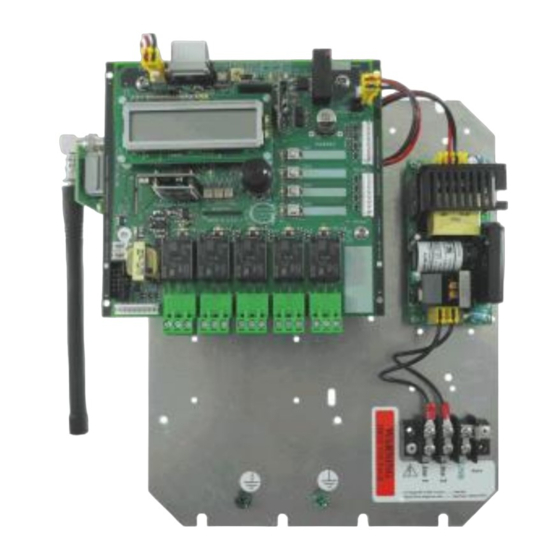
The RXC-3000 comes equipped with 5 Single Pole Single Throw (SPST) high power relays. Additionally, the RXC-3000 has an output header where the installer can tap into the transistors that control the relays as well as 3 additional transistors that are open for special use. During the running of a script, a command in the script will tell an output to turn on and/or off. -
Page 11: Menus And What They Mean
A double click of the “twist-n-touch” knob will allow entry into the settings menus. Note: Sub-menu screen will time out in 3 minutes and return the RXC-3000 to normal operation without Twist-n-Touch knob movement. Live DTMF* and LIVE TTS PAGING* do not time out. - Page 12 RXC-3000 Hardware Installation and User Guide “Adjust Settings” Screens Enter to adjust the unit’s Enter to select radio or ADPCM addresses for System, Group, audio sent to PA port. and Unit. (refer to Prog. Guide Sec. 21) (refer to Prog. Guide Sec. 13) Enter to adjust the radio’s...
-
Page 13: Installing
Genave offers a pole mounting kit (HDW-5051) for the RXC-3000. The kit can be used to attach the RXC-3000 to a wood pole with screws or lags, customer supplied, or it can be attached to a steel pole with the optional stainless steel banding. -
Page 14: Pole Mounting
RXC-3000 Hardware Installation and User Guide Pole Mounting HDW-5051 HDW-5051 shown with optional stainless steel bands and mounting accessories 14 of 46 9000-0000-040 Revision 10 Genave Electronics... -
Page 15: Ac Wiring
Power Connection The RXC-3000 requires 90 to 250 volts AC power to operate. The unit is supplied with a 3 position barrier terminal block. The terminal screw size is #6 screw and will accept a forked terminal with a maximum width of .320”. -
Page 16: Dc Wiring
Genave can make a custom length cable for installation. Warning: Make certain that the polarity of the wires is correct. Even though the unit has diode protection for reverse voltages, damage to the RXC-3000 may occur if the polarity is reversed. Battery Backup The battery backup consists of a seven amp hour sealed lead acid battery along with a universal input battery charger. -
Page 17: Programming
4) The first time your run ComstarG4, click Edit->Preferences and select the USB drive. The file that holds all of the configuration data for your Genave product will automatically load when you start the ComstarG4 program. If you make changes to the file, use “SAVE AS” and save the new file to the hard drive. -
Page 18: Usb Port, Connector And Cable
Hardware Installation and User Guide USB Port, Connector And Cable The RXC-3000 communicates with a computer over a USB 2.0 port. The port's connection is a mini type B 5 pin USB receptacle. The maximum USB cable length is 16 feet. -
Page 19: Inputs
Input Header Characteristics (J14 and J15) The inputs for the RXC-3000 are ALWAYS pulled low to pin 9 of J14 or J15. You can connect these inputs to switches or opto-couplers. We recommend that they are not connected directly to a digital level source unless there is protection between the two circuits. -
Page 20: Triggering Rxc-3000 From An Input
RXC-3000 Hardware Installation and User Guide Triggering RXC-3000 From an Input The following items describe input triggering: (1) Each of the 8 inputs can start an action script, but only one script per switch. (2) The action scripts need to be setup before a switch can be attached to them. -
Page 21: (Example) Interfacing Rxc-3000 To External Switches
RXC-3000 Hardware Installation and User Guide Relay 5 Relay 4 Relay 3 Relay 2 Relay 1 (Example) Interfacing RXC-3000 To External Switches 21 of 46 9000-0000-040 Revision 10 Genave Electronics... -
Page 22: Outputs
Relay Characteristics The RXC-3000 has 5 high power relays available for use. Each relay can handle 240VAC at 7 Amps. Each relay's outputs are directly connected to a 3 position header (J6 to J10) that can accept wires up to 12 AWG diameter. -
Page 23: Output Header Pinout (Aux Output)(J5)
+12VDC. When the transistors are on, the output will be 0 VDC. Do not connect these pins to any voltage higher than +12VDC since the voltage will go through the relays and into the RXC-3000's power supply. Pin 1 Pin 9 GND... -
Page 24: (Example) Connecting Rxc-3000 To Heavy Loads
RXC-3000 Hardware Installation and User Guide (Example) Connecting RXC-3000 To Heavy Loads 24 of 46 9000-0000-040 Revision 10 Genave Electronics... -
Page 25: Pa Audio Port
The Diagnostics pin is diode protected so that voltages above +5VDC are blocked from damaging the RXC-3000. The diagnostic input serves to tell the RXC-3000 that the amplifier is working properly. A low voltage on this pin indicates that the amplifier is ok. A high voltage on this pin indicates that the amplifier either has a problem or is not connected. -
Page 26: Pinout And Characteristics Of 600 Ohm Audio Port (J12)
Pinout And Characteristics Of 600 Ohm Audio Port (J12) The 600 Ohm audio port is used to connect the audio from the RXC-3000 to a PA system such as the type used in a school, fire station or office building. Most of these systems have audio inputs that are rated as 600 Ohms of balanced audio (600 ohms between the audio wires and no ground reference). -
Page 27: Setting Pa Port Levels
Hardware Installation and User Guide Setting PA Port Levels There are 3 voltage controlled amplifiers on the RXC-3000 that boost the audio from the radio and main IC (PWM) and then a final boost into the 600 Ohm transformer. These amplifiers are controlled by R81, R95 and R100 respectively. -
Page 28: Radio Port
The Radio Interface Port is optimized for use with the Maxon SD series of radios. However, this port can be used to connect the RXC-3000 to any radio or audio source. Here is the pinout of the port: Pin 1 Do Not Use... -
Page 29: Setting Rx Audio Levels
RXC-3000 Hardware Installation and User Guide Tx Audio Level Adjustment Rx Audio Level Adjustment Setting Rx Audio Levels The Rx audio from the Radio Port (J13-pin 10) is supplied directly to the high side of potentiometer R75. This pot should be adjusted to provide 100mV to 200mV of audio on Test Point 1 (just below R75) when receiving 3.0... -
Page 30: Radio Audio Levels To Pa Port
RXC-3000 Hardware Installation and User Guide Radio Audio Levels to PA Port (See Setting PA Port Levels under “PA Audio Port” section of manual) How To Change Frequency (Maxon Radio Only) Please refer to the Programming Guide 9000-0000-041 for more information... -
Page 31: Dtmf Decoder
The decoder circuit requires a gap between character strings of 600 milliseconds to decode the previous string before it can accept another string of characters to decode. Triggering RXC-3000 Off Of A DTMF String Please refer to the Programming Guide 9000-0000-041 for more information... -
Page 32: Two Tone Sequential Decoder
1000 Hz tone and since the CTCSS and DCS tones are out of the range for the decoder, they are not decoded. The result is that the RXC-3000 does not respond to the signal. - Page 33 RXC-3000 it may get delayed by up to 250 milliseconds. If not calculated into the A tone time, this would make the A tone appear too short.
-
Page 34: Triggering Rxc-3000 Off Of A Two Tone Signal
RXC-3000 Hardware Installation and User Guide Triggering RXC-3000 Off Of A Two Tone Signal Please refer to the Programming Guide 9000-0000-041 for more information How To Enter/Adjust Two Tone Signal Strings Please refer to the Programming Guide 9000-0000-041 for more information... -
Page 35: Real Time Clock
The battery for the RTC is a standard 3 Volt CR1612, CR1616, CR1620 or CR1632 battery. To maintain the current time, replace the battery with power applied to the RXC-3000. Install the battery into the holder with the negative side facing into the board and the positive side facing the holder. -
Page 36: Mp3 Audio Player
How Sound Files Are Played To The PA Port When the RXC-3000 runs a script, if it has been told to play a song/sound file, it turns on the MP3 player and tells the player the file number of the song/sound it is to play. The player automatically selects the file from the SD card and begins playing. - Page 37 There are two ways that the audio will end or stop. The first way is for the MP3 to come to the end of the audio file, at which time it will tell the RXC-3000 that the audio is done. The RXC-3000 will then turn off the amplifier port and finish running the script.
-
Page 38: Usb Port
Hardware Installation and User Guide USB Port The USB port is a 5 pin Mini USB connector. When the MP3 module is installed in an RXC-3000, this USB port takes the place of USB module M4 which is normally located near the top of the LCD display. -
Page 39: Heartsafe
Hardware Installation and User Guide Heartsafe To prevent startling people who may be near the RXC-3000 when it starts playing audio files, the MP3 module has the exclusive “Heartsafe” feature developed by Genave. Any MP3 audio can begin softly then rise to full volume over 5 seconds. The rise allows people to prepare themselves for full volume. -
Page 40: How To Program The Sd Card
RXC-3000 Hardware Installation and User Guide How To Program The SD Card To a computer, an SD card looks exactly like a USB memory stick or hard drive. Remove the SD card from the MP3 module and insert it into a USB to SD card adapter. -
Page 41: Installing The Mp3 Module
RXC-3000 Hardware Installation and User Guide Installing the MP3 Module 1. Remove USB module if installed. 4. Use the supplied Kapton tape to secure the wires to the PCB. 2. Install MP3 module 3. Use the supplied blue and yellow wires to make the connections shown. -
Page 42: Adpcm Audio Player
ADPCM unit to play audio #6. There are two ways that the audio will end or stop. The first way is for the ADPCM to come to the end of the song, at which time it will tell the RXC-3000 that the audio is done. -
Page 43: Tf Card (Microsd) Characteristics
To a computer, a TF card looks exactly like a USB memory stick or hard drive. Remove the TF card from the RXC-3000 and insert it into a USB TF card reader. Plug the USB reader into a USB port on your computer and the operating system will locate the card and start working with it. -
Page 44: Fused Output Board
RXC-3000 Hardware Installation and User Guide Fused Output Board Optional fused output accessory board. Takes a TE5 fuse and has a maximum of 5 amps. Optional fused output board 8060-0000-042 DC – DC Converter Optional DC- DC converter. Maximum of 48V in and a maximum of 12V out. -
Page 45: Page Intentionally Blank
RXC-3000 Hardware Installation and User Guide Page Intentionally Blank 45 of 46 9000-0000-040 Revision 10 Genave Electronics... -
Page 46: Page Intentionally Blank
RXC-3000 Hardware Installation and User Guide Page Intentionally Blank 46 of 46 9000-0000-040 Revision 10 Genave Electronics...
Need help?
Do you have a question about the RXC-3000 and is the answer not in the manual?
Questions and answers