Advertisement
Quick Links
This document contains sensitive proprietary information.
All recipients must have a current non-disclosure agreement
on file with M-Audio.
Do not make illegal copies of this document.
The information in this document contains privileged and confidential information. It is
intended only for the use of those authorized by M-Audio. If you are not the authorized,
intended recipient, you are hereby notified that any review, dissemination, distribution
or duplication of this document is strictly prohibited. If you are not authorized, please
contact M-Audio and destroy all copies of this document. You may contact M-Audio at
support@m-audio.com.
© Copyright M-Audio
Confidential
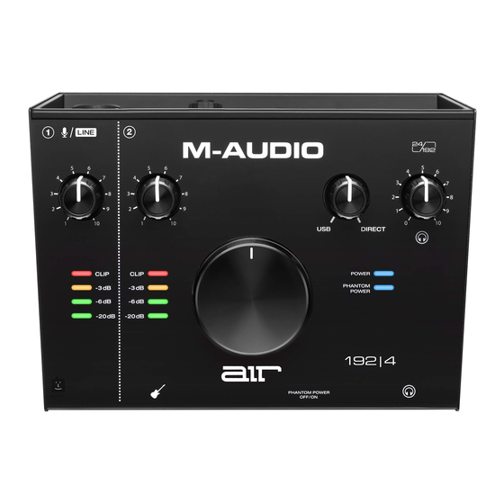
M-Audio
AIR 192|4
[MIUEc]
Service Manual
v1.1
2019-10-09
ATTENTION!
M-Audio Service Manual
Advertisement

Related Manuals for M-Audio AIR 192/4


Summary of Contents for M-Audio AIR 192/4
- Page 1 Do not make illegal copies of this document. The information in this document contains privileged and confidential information. It is intended only for the use of those authorized by M-Audio. If you are not the authorized, intended recipient, you are hereby notified that any review, dissemination, distribution or duplication of this document is strictly prohibited.
- Page 2 As the owner of the copyright to the Manual, M-Audio does not give you the right to copy the Manual, and you agree not to copy the Manual without the written authorization of M- Audio.
- Page 3 ALL REPAIRS DONE BY ANY ENTITY OTHER THAN AN AUTHORIZED M-AUDIO SERVICE CENTER SHALL BE SOLELY THE RESPONSIBILITY OF THAT ENTITY, AND M-AUDIO SHALL HAVE NO LIABILITY TO THAT ENTITY OR TO ANY OTHER PARTY FOR ANY REPAIRS BY THAT ENTITY.
- Page 4 The product is exposed to water or excessive moisture, c. The AC power supply plug or cord is damaged, d. The product shows an inappropriate change in performance or does not operate normally, or e. The enclosure of the product has been damaged. Confidential M-Audio Service Manual...
- Page 5 SERVICE MANUAL MODEL: air 192|4 SPECIFICATIONS Mic Input 1 (balanced XLR) Frequency Response 20 Hz – 20 kHz (+0.1 dB) Dynamic Range 104 dB (A-weighted) Signal-to-Noise Ratio 104 dB (+1.0 dBu, A-weighted) THD+N 0.003% -128 dBu (max gain, 150 Ω source, A-weighted) Preamp EIN Max Input Level +1.5 dBu...
- Page 6 Headphone Output (1/4” [6.35 mm] TRS) THD+N 0.005% 10 Ω Output Impedance General Power USB-bus-powered Dimensions 6.0” x 2.8” x 7.8” 15.2 cm x 7.1 cm x 19.8 cm (width x depth x height) Weight 2.0 lbs. 0.9 kg...
-
Page 7: Disassembly Procedures
DISASSEMBLY PROCEDURES DISASSEMBLE THE BOTTOM PANEL AND BACK PANEL. (A) REMOVE 6 PCS HEXAGON SOCKET SCREW FROM THE BOTTOM PANEL. (B) REMOVE 4 PCS SCREW FROM THE BOTTOM PANEL. (C) REMOVE 3 PCS HEXAGON SOCKET SCREW FROM THE BACK PANEL. (D) REMOVE 2 PCS NUT FROM THE BACK PANEL. - Page 8 DISASSEMBLE THE VR PCB ASS’Y. (A) REMOVE 8 PCS SCREW FROM THE VR PCB ASS’Y. (B) REMOVE 4 PCS KNOB FROM THE VR PCB ASS’Y. (C) REMOVE 4 PCS NUT FROM THE VR PCB ASS’Y. (D) REMOVE 4 PCS WASHER FROM THE VR PCB ASS’Y. (Fig3)
-
Page 9: Wiring Diagram
WIRING DIAGRAM (US.AUS.JIS.NZ) -
Page 10: Packing Diagram
PACKING DIAGRAM (US.AUS.JIS.NZ) -
Page 11: Explode Diagram
EXPLODE DIAGRAM (US.AUS.JIS.NZ) EQUENCIAL NO EXPLODE DIAGRAM WILL BE MARKED ON REF.COLUMM OF BOM LIST... - Page 12 MIUECMAO01 0 MIUECMAO01 MIUEC USB USA 1 CA241410001 USB 2.0 Cable 1m A/C Black 1 CA241510001 USB 2.0 Cable 1m C/C Black 1 FFC5005001503 FFC 50P 0.5mm Length:150mm 1 LAC22MAO109 Serial Number Label 1 LAC53MAO118 Safety Label 1 LAC62MAO110 Bar Code Label(CODE39) 0.125 1 LAC62MAO111 Bar Code Label(GTIN14)
- Page 13 2 AL1-60-2222 Ecap 22UF/16V SMD-B C57,72,73,92,95,99,100,107,108 2 AL2-01-5822 DIODE IN5822 2 AL2-50-4149 Diode Single 1N4148 100V 200mA SOT-23 D8,9 2 AL2-51-4401 Transistor 2N4401 NPN SOT-23 (Transistor MMBT4401LT1 NPN SOT-23) 2 AL2-51-4403 Transistor 2N4403 PNP SOT-23 Q4,5 2 AL2-52-5242 Diode MMBZ5242B 2 AL2-54-6306 Mosfet FDC6306P P-CH SSOT-6 Q2,3...
- Page 14 2 JKK6J62AL6E2KY TRS Jack 7P 90° Female J5,6 2 JKK6J80LAA12E2K TRS Jack 13P 90° Female Dual 2 JKK6X01-6-3B XLR Jack 11PIN 90° Female Combo 2 PC15A005 Main PCB 4Layer FR-4 184x142mm 2 RS000004J06 RES 0Ω 5% SMD 1206 2 RS000010J03 RES 0Ω...
- Page 15 2 CS104K5003X7R CCAP SMD 0.1uF/50V 10% 0603 X7R C1,2,7,8,23,24,27~31,34,35,37,38 2 CS180J5003NPO CCAP SMD 18pF/50V 5% 0603 NPO C3,4 2 CS221J5003NPO CCAP SMD 220pF/50V 5% 0603 NPO C9,21 2 CS470J5003NPO CCAP SMD 47pF/50V 5% 0603 NPO 2 CS471J5003NPO CCAP SMD 470pF/50V 5% 0603 NPO 2 CS681J5003NPO CCAP SMD 680pF/50V 5% 0603 NPO C39,40...
- Page 16 :20mm Dual Unit 2 VRR10401702 Potentiometer Rotary Volume:100k Length: 17.5mm 2 VRR50201703 Potentiometer Rotary Volume:5KB/05C 10K, P1,2 Length:16.5mm Dual-unit 1 TWPT1310619702 Knob Assembly 2 PT11106499 Decoretive(18.0mm) 2 PT113003002 Knob Inlay(BLACK CHROME) 2 PT13106197 Knob(ABS BLACK) 1 WS142035004O Teflon Spacer...
- Page 17 [MIUEc] AIR 192|4 Test App v1.0.3 procedure Test App 1. Input Gain 2. LED Meters 3. USB / Direct Blend 4. Headphone Level 5. Monitor Level 6. Power LED 7. +48V (Phantom Power) LED +48V Phantom Power Test 1. Switch the +48V phantom power to the right (turning it on). 2.
- Page 18 D B N u b t u j d E Y Q ! ) U N * ; ! !
- Page 19 D B N u b t u j d E Y Q ! ) U N * ; ! !
- Page 20 D B N u b t u j d E Y Q ! ) U N * ; ! !
- Page 21 D B N u b t u j d E Y Q ! ) U N * ; ! !
- Page 22 D B N u b t u j d E Y Q ! ) U N * ; ! !
- Page 23 D B N u b t u j d E Y Q ! ) U N * ; ! !
- Page 24 D B N u b t u j d E Y Q ! ) U N * ; ! !
- Page 25 D B N u b t u j d E Y Q ! ) U N * ; ! !
- Page 26 D B N u b t u j d E Y Q ! ) U N * ; ! !
- Page 27 D B N u b t u j d E Y Q ! ) U N * ; ! !
- Page 28 D B N u b t u j d E Y Q ! ) U N * ; ! !
- Page 29 D B N u b t u j d E Y Q ! ) U N * ; ! !
Need help?
Do you have a question about the AIR 192/4 and is the answer not in the manual?
Questions and answers