Table of Contents
Advertisement
Quick Links
Advertisement
Table of Contents

Subscribe to Our Youtube Channel
Related Manuals for Opvimus DA-4PM/0


Summary of Contents for Opvimus DA-4PM/0
- Page 1 DA-4PM/0 Mainframe for 4 modular amplifiers DA-4PM/0 version 1.0.E...
-
Page 3: Table Of Contents
Mainframe for 4 modular amplifiers Table of contents INTRODUCTION ............................4 FRONT VIEW ............................4 DA-4PM/0 REAR VIEW ..........................5 CONNECTION ............................5 4.1. Speakers connection ..........................5 4.2. Inputs connection ..........................6 4.3. Standby mode control connection ......................7 4.4. -
Page 4: Introduction
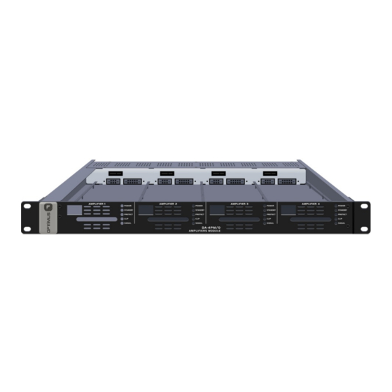
3. Slot 3 for amplifier module (amplifier not included). 8. Amplifier module CLIP LED indication (see section 8). 4. Slot 4 for amplifier module (amplifier not included). 9. Amplifier module SIGNAL LED indication (see section 8). 5. Amplifier module POWER LED indication (see section 8). DA-4PM/0 version 1.0.E... -
Page 5: 4Pm/0 Rear View
DA-4PM/0 Mainframe for 4 modular amplifiers 3. DA-4PM/0 REAR VIEW Figure 2 DA-4PM/0 Ground terminal. 15A Mains fuse for 220-240 VCA. The device is set up with a 15A fuse to operate on a main voltage of 220-240 VAC. To work with other main voltages (100-127 VAC), replace the 15A fuse with the 30A fuse supplied with the device. -
Page 6: Inputs Connection
The connection between the pin 8 and the shielding of the RJ45 connector to the GND Pin 7: Not used. of the DA-4PM/0, and the connection between the GND to the earth of the DA-4PM/0, Internal Pin 8: jumpers x_JP1 is made through the internal jumpers. -
Page 7: Standby Mode Control Connection
(MP-WDC Series) to be used in safety installations through their connection to a 24VDC battery system. Figure 8. If you use this connection, you must place the Figure 8 corresponding 24VDC fuse (see section 6. AMPLIFIER MODULE FUSE PLACEMENT). DA-4PM/0 version 1.0.E... -
Page 8: Inserting The Power Amplifiers Modules
DA-4PM/0 Mainframe for 4 modular amplifiers 5. INSERTING THE POWER AMPLIFIERS MODULES 1. Remove the frontal plate. Figure 9 2. If you want to use slots 2, 3 or 4, remove the corresponding slot panel. Figure 10 DA-4PM/0 version 1.0.E... - Page 9 DA-4PM/0 Mainframe for 4 modular amplifiers 3. Insert the amplifier module by fitting it into the slot guides. Figure 11 4. Fasten the amplifier module by means of the hot-swapping screw. Figure 12 DA-4PM/0 version 1.0.E...
-
Page 10: Amplifier Module Fuse Placement (Only Mp-Wdc Amplifiers Series)
(1 + 1 spare fuse). ATTENTION: Each amplifier model has a different value fuse, depending of the amplifier power. See Table I. Figure 14 TABLE I DC FUSE AMPLIFIER VALUE MP-120WDC 7.5A MP-150WDC MP-250WDC MP-300WDC MP-460WDC DA-4PM/0 version 1.0.E... -
Page 11: 4Pm/0 Technical Characteristics
DA-4PM/0 Mainframe for 4 modular amplifiers 7. DA-4PM/0 TECHNICAL CHARACTERISTICS Input contacts Standby activation contact (independent for each amplifier). Audio inputs 4 inputs, 0dB (775 mV rms). Audio outputs 4 Independent audio outputs for speakers lines (100V). Max. Output level... -
Page 12: Modular Amplifiers Mp-Wd1 Series
POWER, STANDBY, PROTECT, CLIP and SIGNAL THD+N (@1kHz) <0.6% <0.6% <0.6% <0.6% <0.6% Consumption Standby 3.5W Idle 6.5W 7.2W 7.2W 7.2W 134W 165W 276W 339W 520W AC Fuse NOT USED IN MP-WD1 SERIES WITH DA-4PM/0 MAINFRAME Power supply (Mainframe) 100-240 VAC DA-4PM/0 version 1.0.E... -
Page 13: Modular Amplifiers Mp-Wdc Series
POWER, STANDBY, PROTECT, CLIP and SIGNAL THD+N (@1kHz) <0.6% <0.6% <0.6% <0.6% <0.6% Consumption Standby 3.5W Idle 6.5W 7.2W 7.2W 7.2W 134W 165W 276W 339W 520W DC Fuse 7.5A 100-240 VAC Power supply (Mainframe) Secondary power supply 24 VDC DA-4PM/0 version 1.0.E... -
Page 14: Document Version Tracking
10. DOCUMENT VERSION TRACKING Reference system Type of Document Confidentiality DA-4PM/0 Installation and operation guide Date Modifications Content Written by: 1.0.E May 2020 Version R+D Department Approved By Function Date Ferran Gironès i Puig R+D Director 05/2020 DA-4PM/0 version 1.0.E... -
Page 15: Guarantee
• Amendments or corrections made to the details of the guarantee certificate Fax. 972 21 84 13 or purchase invoice. e-mail:girona@optimus.es 1999/44/CE • Fejlure to produce the original invoice or the absence of a date on this. DA-4PM/0 version 1.0.E...
Need help?
Do you have a question about the DA-4PM/0 and is the answer not in the manual?
Questions and answers