
Related Manuals for RPM MHPWS-QNN Series

Summary of Contents for RPM MHPWS-QNN Series
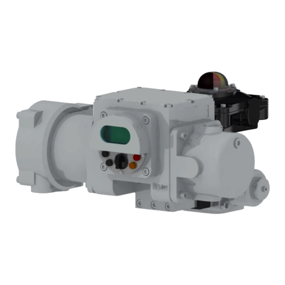
- Page 1 Electro-Hydraulic Actuators MHPWS-QNN Series Maintenance Manual M-MHPWS-QNN-CAN-EN V1.02, 2020.05.21...
- Page 2 Important Notice! This manual consists of content to guide the installation and operation of the MHPWS-QNN. Safety notices in the manual are specific precautions to reduce the risk of personal injury and equipment damage. Users should read and understand these instructions. Failure to observe these safety notices may result in personal injury, equipment damage, and voiding warranty.
-
Page 3: Table Of Contents
Table of Contents 1. Maintenance ..........1.1 Periodic Maintenance Procedures 1.2 Troubleshooting 2. -
Page 4: Maintenance
1. Maintenance 1.1 Periodic Maintenance Procedures Every individual part is thoroughly inspected and tested before being assembled after which an extensive performance and functions test is executed to guarantee maximum quality and reliability. However, our products are still subject to wearing after significant usage or exposure to harsh environmental conditions, which may reduce the MHPWS-QNN’s performance or cause malfunction. -
Page 5: Troubleshooting
1.2 Troubleshooting If there are issues that arise during the monthly / biyearly inspections or during operation, refer to the following list of issues and solutions. 1) Power not delivered Issue 1-1 : The display on the front of the MHPWS-QNN is off. à... - Page 6 Issue 2-3 : Motor does not function, Display shows the following message after 15 seconds (time varies on the model): ‘6. VALVE JAMMED’ à Solution 1 : Open the Upper Cover to reveal the motor driver, and ensure that power is supplied properly and the status LED indicator is working properly.
- Page 7 6) Remote signal not delivered Issue 6-1 : Unable to monitor the valves remotely. à Solution 1 : Monitor the valves locally through the display. à Solution 2 : Disconnect all the valve Status cables from the terminal. Test using a multimeter for a flow of electricity between the Common and Signal Cables to ensure that the cause of the problem is not within the MHPWS-QNN.
- Page 8 Issue 6-6 : Unable to remotely operate via 4~20mA (CPT Control) à Solution 1 : Ensure that the specific model of the MHPWS-QNN supports Modulation Mode. Models M and S feature modulation in the NML AI Mode and the Model I in the Step AI Mode. (Models M and S: NML AI Mode, Model I: Step AI Mode) à...
-
Page 9: Disassembly And Assembly
2. Disassembly and Assembly Please be cautious of the following if disassembly of the Main Controller, Power Module Ass’y, Motor Driver, or Position Meter is necessary for repairs or maintenance. ■ Ensure the environment is safe from any flammable gas or electricity. CAUTION ■... - Page 10 2) Power Module Ass’y ② ③ ④ ⑤ ① ① - C.T. Cover ② - Bolt & Washer ③ - Power Module Ass'y ④ - Main Housing ⑤ - Terminal Block Figure 2.2 [ Exploded view of the Power Module Assembly ] ③> from the C.T. Cover a.
- Page 11 3) Motor Driver ① ② ③ ④ Figure 2.3 [ Exploded view of the Motor Driver ] ① - Bolt & Washer ② - Upper Cover ③ - Motor Driver ④ - Bolt for Motor Driver ⑤ - Main housing ①...
- Page 12 4) Position meter ① ② ④ ③ ⑤ ⑥ Figure 2.4 [ Position meter ] ①- Bolts for Cover ②- Cover ③- Bolts for PM Board ④- PM Board ⑤- O-ring ⑥- Housing a. Remove Bolts for Cover <①> and separate the Cover<②> from the Housing<⑥>. The Bolts for Cover <①>...
-
Page 13: Product Assembly
2.2 Product Assembly The product can be assembled in the exact inverse order of disassembly. Please be cautious of the following during assembly. ■ Ensure all parts being sealed are free of any contaminants. CAUTION ■ Apply small amounts of grease (not acidic) on the surface of the seal. ■... -
Page 14: Drawing
4. Drawing 4.1 Exploded View Drawing Figure 4.1 [ Exploded view of the MHPWS-QNN ] M-MHPWS-QNN-CAN-EN... -
Page 15: Parts List
4.2 Parts List DESCRIPTION MATERIAL Q'TY REMARK Main Housing AC4C-T6 RND14-015-A-001 01-1 Tank Pipe STS304 Ø6 X 1T X 125L (M6) 01-2 Plug STS316 DVSTI-M10ED (M10X1.0P) 01-3 Pressure Plug PT1/8 01-4 O-Ring AN-166 01-5 O-Ring AN-109 01-6 Oil Seal Ø14 X Ø25 X 7 Pump Cover AC4C-T6 RND14-015-A-004... - Page 16 DESCRIPTION MATERIAL Q'TY REMARK Name Plate STS304 RND15-024-A-011 17-1 Button Head Wrench Bolt STS304 M4 X 0.7P X 5L Power Module Ass’y RPMTECH MHP-A1S46-AA-MAIN 18-1 Roundhead + Home Sems Bolt SS400 M4 X 0.7P X 5L Terminal Block PBT+GF30% RND15-004-A-013 19-1 Wrench Bolt STS304...
- Page 17 MEMO M-MHPWS-QNN-CAN-EN...
Need help?
Do you have a question about the MHPWS-QNN Series and is the answer not in the manual?
Questions and answers