
Related Manuals for RPM MHPWS-QNN Series

Summary of Contents for RPM MHPWS-QNN Series
- Page 1 Electro-Hydraulic Actuators MHPWS-QNN Series User Manual Doc.No. : U-MHPWS-QNN-CAN-EN V1.01, 2020.03.27...
- Page 2 Important notice! This manual consists of content to guide the installation and operation of MHPWS-QNN product. Safety notices in the manual are specific precautions to reduce the risk of personal injury and equipment damage. Users should read and understand these instructions. Failure to observe these safety notices may result in personal injury, equipment damage, and voiding warranty.
-
Page 3: Table Of Contents
Table of Contents 1. Introduction ..........4 1.1 MHPWS-QNN Parts 1.2 Identification 2. -
Page 4: Introduction
The MHPWS-QNN series can generate an output torque of 600 Nm to 32,000 Nm depending on the configuration of the hydraulic cylinder and oil pressure settings. This series of products can be installed directly on most valves without a gear reducer. -
Page 5: Mhpws-Qnn Parts
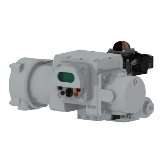
1.1 MHPWS-QNN Parts ① ② ③ ④ Figure 1.1 [MHPWS-QNN Parts] ① Power Pack (MHPWS) ② Hand Pump ③ Position Meter ④ Hydraulic Quarter Turn Cylinder U-MHPWS-QNN-CAN-EN... - Page 6 1.2 Identification Each product component (MHPWS-QNN, Position meter) has a Nameplate in the following location: ① ② ①- MHPWS-QNN ②- Position Meter Figure 1.2 [MHPWS-QNN Nameplate Location] 1) Identification data on the MHPWS-QNN nameplate Figure 1.3 [MHPWS-QNN Nameplate] 1 MODEL Model number of the MHPWS-QNN 2 INPUT RATING Power input compatibility...
- Page 7 2) Identification data on the Position meter nameplate POSITION METER RE-01 K-079581 MODEL S / N 2011. 01. 01 DC-12V 0.2A DATE POWER OUTPUT 0-20mA 4-20mA 0-5V 1-5V 0-10V 2-10V √ DATA www.rpmtech.co.kr Figure 1.3 [Position meter Nameplate] 1 MODEL Model number of the Waterproof Position Meter 2 S / N Manufacture number 3 DATE...
-
Page 8: Safety
2. Safety 2.1 User Safety User(s) of this product must read this manual thoroughly before installation and comprehend all of the functions that this product is equipped with. Any tampering or dismantling of the product should be avoided. 2.2 Mechanical and Electrical Safety Please supply power to the product according to the details specified on the WARNING nameplate of the product. -
Page 9: Packaging
2.5 Packaging Packaging is environmentally friendly making it easy to disassemble and recycle. Packaging material consists of wood, cardboard, and paper. We recommend recycling if possible, and advise proper disposal of the materials in a designated place to prevent detrimental impact on the environment. 2.6 Installation Precautions Upon delivery of the MHP Series product, the user should commence a thorough inspection of the product(s) for damage, loose or missing screws. -
Page 10: Installation
3. Installation 3.1 Valve Alignment 3.1.1 Shaft Coupling Connection In the case where the valve shaft of the MHPWS-QNN does not align with the shaft connection, manufacture a shaft coupling and connect before installing the actuator. Ensure that the key and the shaft coupling does not inflict any damage. -
Page 11: Connecting Power And Signal Cables
3.3 Connecting Power and Signal Cables 1) Make sure a single-phase 110V ~ 220V AC power cable is connected, and then open the terminal cover of the MHPWS. Exterior Grounding 2) Connect the power cable to terminals 1 and 2 on the terminal block to ground the cable Figure 3.2 [Grounding connection position] 4SQ is recommended for the grounding cable. -
Page 12: Position Setting
3.4 Position Setting 3.4.1 Stroke Limiter Setting - Full Close Stroke Limiter Setting – 1) Set the selector switch on the MHPWS-QNN to SET MODE as shown in Figure 3.5 and press the CLOSE button to ensure that the valve is fully closed. The main controller will not perform the close operation if the gate positioner is in NOTE the full close limit state. - Page 13 - Full Open Stroke Limiter Setting - 1) Set the selector switch on the MHPWS-QNN to SET MODE as shown in Figure 3.7 and press the OPEN button to ensure that the valve is fully open. The main controller will not perform the close operation if the gate positioner is in NOTE the full close limit state.
- Page 14 3.4.2 Testing for Proper Functioning Upon installment of the MHPWS-QNN, perform the Full Close / Full Open operations to ensure proper functioning of the valve’s disk. Check that the F/O and F/C indication lights next to the display and the position meter are functioning properly according to the signals sent by the gate positioner.
-
Page 15: Open/Close Calibration Function
3.4.3 OPEN/CLOSE Calibration Function The MHPWS-QNN opening and closing calibration can be performed using the front switch, and the procedure is as follows. 1) Set the SELECT switch to Local Mode. LOCAL REMOTE Figure 3.10 [Select Switch-Local Three Mode)] 2) Press and hold the CAL button for about 3 seconds until the display shifts to Calibration settings. 3 sec F / O R / S... -
Page 16: Full Close Calibration Instructions
3.4.4 FULL CLOSE Calibration Instructions R / S R / S F / O F / O F / C F / C CLOSE OPEN Figure 3.13 [Calibration Example-1] 1) Press the OPEN/CLOSE buttons to move to the Calibration menu item ('1 MANUAL F/C'). 2) Press the CAL button to select the ‘1 MANUAL F/C’... -
Page 17: Precautions During Calibration
3.4.5 Precautions During Calibration 1) The valve position displayed during calibration is based on factory calibrated settings of the position meter (potentiometer). The valve position displayed after the calibration is the newly calibrated position. 2) The user can only enter calibration value that is greater/less than 10% of the valve position to prevent any errors during the calibration process. -
Page 18: Operation
4. Operation 4.1 Normal Operations Check / Inspection 4.1.1 Normal Operation 1) Turn on the power and check the version. EN10 V2.0 MHP_Q_ F / O R / S EN10 : Model & Card Kind&Accuracy F / C : Program Version Figure 4.1 [Normal Power &... - Page 19 4.1.2 Changing Operation Modes Use the Select switch to alternate between the 3 modes of operation. LOCAL Mode is for local manual operation. SET Mode is for accessing the function settings and is mostly used during the initial setup of the MHPWS-QNN. REMOTE Mode allows the MHPWS-QNN to be monitored and operated remotely.
- Page 20 3) REMOTE Operation Mode - Used for operating remotely LOCAL REMOTE - Mode selectable by two inputs on the control input terminal. (* Refer to Remote Control Instruction Manual) - Limited by model and card types. è Remote Normal Mode - OPEN/CLOSE at constant speed.
-
Page 21: What To Do When The Alarm Flashes / Sounds
4.1.3 What to Do When the Alarm Flashes / Sounds When the valve operation encounters problems, the ALM LED indicator on the lower right will flash and an emergency alarm will sound simultaneously. If this happens, inspect the MHPWS-QNN to identify and resolve the issue before running it again. -
Page 22: Manual Override
4.2 Manual Override The following are instructions on how to take manual control over the MHPWS-QNN using the manual hand pump in the case of a power failure or a malfunctioning hydraulic actuator. 1) Turn ① to align the direction. (clockwise to close, counterclockwise to open) 2) Turn ②... -
Page 23: Maintenance
5. Maintenance 5.1 Troubleshooting Types of Indications of Recommended Solution Malfunctions Malfunction - Check the main power supply line. Refer to the electrical No Power Display is off blueprint in referencing the circuit diagram. - Check the fuse of main controller. - Check the motor power line. -
Page 24: Specifications
6. Specifications 6.1 Model Information MODEL GUIDE QUARTER TURN ACTUATORS 0011 ① ② ③ ④ ⑤ ⑥ ⑦ ⑧ ⑨ ⑩ ⑪ ⑫ CODE DESCRIPTION Single Motor Series ① Power Pack Dual Motor Series Water proof ② Enclosure Explosion proof AC 1Ø... -
Page 25: Product Specifications
6.2 Product Specifications TECHNICAL DATA QUARTER TURN ACTUATORS CLASS ELECTRIC DISPLACEMENT WORKING OPERATION POWER PACK ENCLOSURE MOTOR (kW) (l/min) PRESSURE (bar) MODE MHPX Ex d II B T4 Standard: 1 Standard: 160 E(L), G, K, M, S, I Option: 0.4, 2, 3 Option: 40∼210 MHPW IP68... - Page 26 MEMO U-MHPWS-QNN-CAN-EN...
Need help?
Do you have a question about the MHPWS-QNN Series and is the answer not in the manual?
Questions and answers