Table of Contents
Advertisement
instructional information provided with the boiler. Install, start and service the boiler only in the sequence and methods given in these
instructional information provided with the boiler. Install, start and service the boiler only in the sequence and methods given in these
instructions. Failure to do so can result in severe personal injury, death or substantial property damage.
instructions. Failure to do so can result in severe personal injury, death or substantial property damage.
Do not use the boiler during construction.
Do not use the boiler during construction.
the burner, resulting in possible severe personal injur
the burner, resulting in possible severe personal injur
free air supply. Follow the instruction manual procedures to duct air to the boiler air intake. If the boiler has been contaminated by operation
free air supply. Follow the instruction manual procedures to duct air to the boiler air intake. If the boiler has been contaminated by operation
with contaminated air, follow the instruction manual guidelines to clean, repair or replace the boiler if necessary.
with contaminated air, follow the instruction manual guidelines to clean, repair or replace the boiler if necessary.
x these instructions near to the boiler/water heater. Instruct the building owner to retain the instructions for future use b
x these instructions near to the boiler/water heater. Instruct the building owner to retain the instructions for future use b
service technician, and to follow all guidelines in the User's Information Manual.
service technician, and to follow all guidelines in the User's Information Manual.
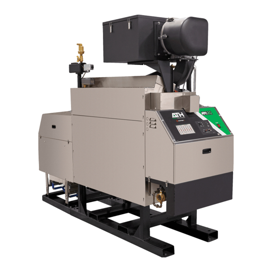
Cast Iron Condensing Boilers
Models KN-6, KN-10, KN-16,
KN-20, KN-26 and KN-30
Models KN6
KN20
KN40
Control Adjustment and Operation Instructions
This instruction manual applies only to Advanced
Thermal Hydronics firmware version 4.15 on
version 3.x control boards.
To replace firmware on an existing boiler, contact
the factory for assistance.
Also read and follow:
KN-Series Gas Boiler Installation
and Operating Instructions
KN-Series Virtuoso 10:1
Supplement Control Manual
er/technician. Read and follow this manual, all supplements and related
er/technician. Read and follow this manual, all supplements and related
Construction dust and particulate, particularly drywall dust, will cause contamination of
Construction dust and particulate, particularly drywall dust, will cause contamination of
KNV3TS-06/2022
With Touch Screen Display
+
+
, KN10
, KN16
+
+
+
, KN26
, KN30
+
e boiler can only be operated with a dust-
e boiler can only be operated with a dust-
06/2022 Copyright Mestek, Inc.
+
,
and
Advertisement
Table of Contents

Subscribe to Our Youtube Channel
Related Manuals for ATH HEATNET KN Series


Summary of Contents for ATH HEATNET KN Series
- Page 1 KNV3TS-06/2022 With Touch Screen Display Cast Iron Condensing Boilers Models KN-6, KN-10, KN-16, KN-20, KN-26 and KN-30 Models KN6 , KN10 , KN16 KN20 , KN26 , KN30 KN40 Control Adjustment and Operation Instructions This instruction manual applies only to Advanced Thermal Hydronics firmware version 4.15 on version 3.x control boards.
- Page 2 Information contained in this publication regarding device applications and The Advanced Thermal Hydronics name and logo, Mestek name the like is provided only for your convenience and may be superseded by and logo, KN, HeatNet, and H-Net name and logo are registered updates.
-
Page 3: Table Of Contents
TABLE OF CONTENTS HeatNet Control V3 3.x TABLE OF CONTENTS TABLE OF CONTENTS ....................................3 Introduction ..........................................6 KN-S V3 H ............................. 5 ERIES ONTROL Features & Specifications ....................................8 ................................ 8 TANDARD EATURES VERVIEW KN-Series Plus Additional Features ................................ 10 Setting Up the Flow Sensor .................................. -
Page 4: Settings
TABLE OF CONTENTS HeatNet Control V3 3.x Combustion Air Damper ....................................66 Outdoor Reset ........................................66 Sensors ..........................................67 Stack Temperature ......................................67 USB Features ........................................68 Saving and Restoring Configuration Settings ............................... 69 Diagnostics ........................................75 Blower Protection ......................................75 Communications ...................................... -
Page 5: The Kn-Series V3 Heatnet Control
INTRODUCTION HeatNet Control V3 3.x The primary purpose of the control is to maintain the boiler Introduction water temperature at the supply or the header sensor using a target setpoint. This function is displayed in the Home Screen. While performing this task, the control also The KN-Series V3 HeatNet Control monitors dedicated external limits in a limit string and provides an orderly shutdown and fault indication in the... -
Page 6: Introduction
INTRODUCTION HeatNet Control V3 3.x This adjustment occurs when the newly added MEMBER Figure 1 Heat Band boiler enters its ON CALL state (default setting). This can be changed to PILOT when the new boiler is called using the menu: The control algorithm is based upon a Heat Band (Figure 1), at the center of which is the setpoint. - Page 7 INTRODUCTION HeatNet Control V3 3.x In a stand-alone installation the MEMBER typically receives its command signals internally and operates based upon the outlet water temperature and the established settings in the menu (LOCAL SETPOINT) to start/stop the burner, and/or to modulate the firing rate. If the operating limit is exceeded, or if an interlock trips, the boiler is shut down.
-
Page 8: Features & Specifications
FEATURES & SPECIFICATIONS HeatNet Control V3 3.x System Return sensor input. HeatNet Version 3.x Features & Enhanced bootloader and firmware storage. One Specifications firmware storage location for user updates. One firmware program that always remains resident so that a factory program can be restored. Primary loading is Discontinued Features from Version 2.x with a flash drive. - Page 9 FEATURES & SPECIFICATIONS HeatNet Control V3 3.x Return (Boiler Inlet) Temperature, and Header 24. Freeze Protection allowing automatic starting of (Common System Supply) Temperature. boiler(s) using (2) Failsafe modes. Automatically detects the optional temperature sensors 25. Adaptive Modulation. When additional boilers are on power up (OAT sensor manual enable in “Settings”...
-
Page 10: Kn-Series Plus Additional Features
FEATURES & SPECIFICATIONS HeatNet Control V3 3.x KN-Series Plus Additional Features To maximize efficiency, the KN-Series Plus control now engages a secondary heat exchanger pump. A flow sensor monitors the flow through the stainless-steel secondary heat exchanger. This preheats the system return water to decrease energy consumption and increases the overall efficiency in excess of 95%. - Page 11 FEATURES & SPECIFICATIONS HeatNet Control V3 3.x A current sensor with a normally open switch landed on J11B, 7 & 8, is used to provide proof that the secondary Heat Exchanger pump is operating. Figure 4 Displays GPM at Local Water Flow Prove Icon The KN-Series Plus boilers come equipped with a flow sensor that sends flow information to the HeatNet control and display’s the water flow information in GPMs at the “Local Flow”...
-
Page 12: Setting Up The Flow Sensor
FEATURES & SPECIFICATIONS HeatNet Control V3 3.x Setting Up the Flow Sensor Prior to making any adjustments to the “Glycol Mix: %” or the “Flow Prove: GPM”, make sure the correct boiler size is chosen in the “Boiler Type” menu, and the defaults are loaded. When Glycol is added to a system the flow characteristics of the water are affected, so it is important to enter the correct Glycol Mix % value. - Page 13 FEATURES & SPECIFICATIONS HeatNet Control V3 3.x The boiler has a heat demand and will not start until the programmed GPM requirement is met. In this case the minimum flow is below the required 16 GPM so the boiler will not start. The flow proof has expired and then enters a fault condition.
-
Page 14: Specifications
FEATURES & SPECIFICATIONS HeatNet Control V3 3.x Specifications Control Microprocessor based PID modulating control (NOT a safety limit) Environment -40 ° to 140 ° , <90% RH non-condensing Input Power 24 VAC, 500 mA Relays System Pump, Damper, Circulator, Alarm, DHW Pump (v2.x), 8A 250 VAC resistive K8 on J4.2 &.6 for Base Loading version 2.x Control 24 VAC –... -
Page 15: Components & Accessories
FEATURES & SPECIFICATIONS HeatNet Control V3 3.x Components & Accessories Part Number Component 40-00751-001 KN-Series Control Board Version 3.x 40-00756-001 KN-Series Plus Control Board Version 3.x 40-00752-002 Color Touch Panel Display 40-00752-003 Touchscreen Display W/Plastic Enclosure 02-3926 ACI/10K-CP-BP Temperature probe (bullet type, 1x.250 inch) 02-4283 ACI 10k-CP-I-NW Supply, Header, Return Sensors 02-4285... -
Page 16: Setup & Operation
SETUP & OPERATION HeatNet Control V3 3.x The MASTER now checks all of the runtimes to determine SETUP & OPERATION which boiler has the least runtime based on the MIN RUNTIME setting in SETTINGS: FIRING MODE: The MIN RUNTIME setting is the minimum runtime interval in hours that is used to compare boiler to boiler runtimes. -
Page 17: Mixed Boiler Types Using Priority Sets
SETUP & OPERATION HeatNet Control V3 3.x The ignition control begins its cycle and provides an setpoint. The system will maintain the setpoint until the load output signal from terminal 4 to the H-Net control J5 demand increases or decreases. Blower. -
Page 18: Mixed Boiler System Operation
SETUP & OPERATION HeatNet Control V3 3.x If the start condition for Priority 1 is met, all boilers in the Mixed Boiler System Operation Priority 1 set will fire based on runtime. Once all boilers in the Priority 1 set have fired, the Priority 2 set of boilers will Starting Boilers: fire based on runtime. - Page 19 SETUP & OPERATION HeatNet Control REV 3.47-1 Figure 7 Mixed Boilers: Example: Condensing/Non-Condensing In the example Mixed Boilers: Condensing/Non- Condensing, condensing boilers and non-condensing boilers are used, but other combinations may also be used. Another example could use (2) small boilers and set them to Priority 1 and then use (3) larger boilers and set them to Priority 2.
-
Page 20: Start/Stop Priority Conditions
SETUP & OPERATION HeatNet Control V3 3.x Once the Mixed Boilers menu has been entered, the firing START PRIORITY 1 SET order and stop order of the Priority boiler set can be selected Selections (always the lowest runtime first): based on up to (3) conditions in the conditional settings menu. -
Page 21: Selecting Mixed Boilers
SETUP & OPERATION HeatNet Control V3 3.x (Priority 1) and non-condensing boilers (Priority 2) for best Selecting Mixed Boilers performance/economy. There are a few factors to consider when choosing which type of boilers to use in a mixed system. These factors need The default settings for the start and stop conditions of the to be considered when boilers are added or shed. - Page 22 SETUP & OPERATION HeatNet Control V3 3.x Example Systems: Figure 8 Non-Mixed Boiler System When selecting the Priority 1 boiler(s) for a high effective system turndown, the BTU Min Input is selected first. Next, System Effective KN 5:1 the MOD-MAX value of this Priority 1 boiler needs to be MMBTU Turndown greater than: Mod MAX % =...
- Page 23 SETUP & OPERATION HeatNet Control V3 3.x system design BTUs. If the # of boilers become a large Figure 11 Boiler System Response 1 number, a Priority 1 boiler with a higher Min Input may (2) KN2s, (3) KN6s need to be selected. While considering the MOD-MAX value, the lower the MOD-MAX the greater the combustion efficiency since it effectively limits the input rate.
-
Page 24: Mixed System Type 2: Condensing / Non-Condensing
SETUP & OPERATION HeatNet Control V3 3.x Figure 12 Boiler System Response 2 Figure 14 Boiler System Response 4 (1) KN6, (1) KN20, 60% Mod-Max (2) KN2s, (3) KN6s To correct this would require the KN6 to set the MOD- The above Boiler System Response 4 graph illustrates MAX to roughly 90% (Boiler System Response 3: not as another system where 80% is used as the MOD-MAX... - Page 25 SETUP & OPERATION HeatNet Control V3 3.x Figure 16 Mixed Boilers: Example: Condensing/Non-Condensing Figure 17 FIII Boiler Btu Chart (MBH) KN Boiler Btu Chart (MBH) MB/MW 1000 1250 1500 1750 KN10 KN20 KN30 Max Input 1.25M 1.5M 1.75M Max Input Min Input Min Input 200M...
- Page 26 SETUP & OPERATION HeatNet Control V3 3.x 140F, the boiler will respond to the MASTER’s request Using the boiler charts and the examples used in: Mixed System Type 1: High System Turndown, a mixed hybrid that it is available to fire. boiler system can be designed.
-
Page 27: Base Loading, Relay Control
CONTROL METHODS HeatNet Control V3 3.x Base Loading, Relay Control The control has the ability to control (1) base load boiler using the K8 Relay contacts on J4 pins 2 & 6. In order to connect to this plug, (2) wires with pins are required and inserted in J4. - Page 28 CONTROL METHODS HeatNet Control V3 3.x (4) 2 million BTU HeatNet boilers = 8 million BTUs and short cycling situation will arise when the (3) 2 million BTU (1) 6 million BTU Base Load boiler. boilers are running @ 95% and the Base Load boiler is called on.
- Page 29 CONTROL METHODS HeatNet Control V3 3.x Figure 19 Base loading relay 1. First ensure that the SETTINGS: BOILER Base Load RIB Relay TYPE:OPTION: is set to BASE LOAD. The Base Load Relay (K8) will not be enabled/used Enable Input on unless this is selected.
-
Page 30: Setting Up Base Loading
CONTROL METHODS HeatNet Control V3 3.x Return Water Temperature Setting up base loading START menu item: The relay contact will close to The base load boiler is controlled using a set of contacts to enable the boiler when the RETURN IS ABOVE enable it (location J4). -
Page 31: Heating Control Methods
CONTROL METHODS HeatNet Control V3 3.x Heating Control Method 3 Heating Control Methods The third method is to allow a remote 4-20 mA or 0-10 VDC signal to control the firing rate (modulation) of the boiler An overview of the (5) methods for controlling the KN-Series using the 4-20mA input, along with the 4-20mA REMOTE boiler are presented here. -
Page 32: Input Priorities
CONTROL METHODS HeatNet Control V3 3.x The AA terminal, the FAILSAFE mode active, 4-20mA at Input Priorities PRIORITY: HIGHEST, and the HEAT DEMAND input The KN-Series control inputs are prioritized so that (LOCAL) on a MEMBER, are the only inputs that will multiple levels of external control can be employed at the override the H-Net control. -
Page 33: Heating Control Input 3 4-20 M A Control
CONTROL METHODS HeatNet Control V3 3.x Features of the HEAT DEMAND input Figure 23 Stage Control Input include: The control is designed to predict when to start and stop the boiler and keep the setpoint in, or as close to the control band as possible. -
Page 34: Aa/High Fire
CONTROL METHODS HeatNet Control V3 3.x The System Setpoint Timer also needs to be loaded Heating Control Input 4 AA/High Fire periodically to allow the H-Net system to fallback to Method HIGH FIRE input Control: The AA input will fire the boiler 1 in the event communications is lost from the Building at HIGH fire (maximum output of the boiler). -
Page 35: Domestic Hot Water Methods
CONTROL METHODS HeatNet Control V3 3.x AUTO: will handle normal heating only applications. It Domestic Hot Water Methods may also be used when individual boilers have tanks connected and are controlled with the DHW BOILER? Domestic Hot Water control is supported using (6) methods. set to LOCAL. -
Page 36: Dhw Method 1: Dhw Heating Only Using A Dhw Master And Member Boiler(S) Employing H-Net
CONTROL METHODS HeatNet Control V3 3.x DHW Method 1: DHW Heating ONLY using a DHW MASTER and MEMBER Boiler(s) Employing H-Net Example DHW Only, Reverse Return Piping – Method 1. Figure 28 Domestic Domestic Supply Supply Tank Sensor Make Make Pressure Reducing Backflow... - Page 37 CONTROL METHODS HeatNet Control V3 3.x Figure 29 DHW Method 1 Quick Start Settings DHW METHOD 1: DHW Heating ONLY Using a DHW MASTER and MEMBER Boiler(s) MASTER (DHW Only) Settings DHW Use Sensor HeatNet Address MASTER Type Combustion Air Damper Automatic DHW Only Inputs...
- Page 38 CONTROL METHODS HeatNet Control V3 3.x Boilers are started as long as the tank’s water temperature is This method requires a 10k thermistor connected to the below the (DHW SETPOINT – LOWER BAND). The first DHW Sensor input of a DHW MASTER, or a stand-alone boiler, and a DHW tank.
- Page 39 CONTROL METHODS HeatNet Control V3 3.x Now, change the LOWER BAND to the desired system instead of a Header sensor. USE SENSOR in temperature (DHW SETPOINT – LOWER BAND) this example will be set to YES. This will allow the below which boilers are to be added.
-
Page 40: (Master Type : Combination )
CONTROL METHODS HeatNet Control V3 3.x DHW Method 2: Failsafe Combination DHW and Space Heating with a MASTER Boiler and MEMBER Boilers Utilizing Valves (MASTER Type: Combination) Figure 30 In this example the MASTER is not a DHW boiler. MIN 3X PIPE DIAMETERS MAX 10X PIPE DIAMETERS BETWEEN CENTERS System Pump... - Page 41 CONTROL METHODS HeatNet Control V3 3.x Figure 31 DHW Method 2 W/Diverting Valves Quick Start Settings DHW METHOD 2: Combination DHW and Space Heating Using a MASTER Boiler and MEMBER Boiler(s) Employing Diverting Valves MASTER (Space Heating Only W/Valves) Settings MASTER Type HeatNet Address DHW Use Sensor...
-
Page 42: Dhw Method Ailsafe Ombination Dhw And Pace Eating With Amaster Boiler And Member Boilers Tilizing Umps (Master Type Ombination )
CONTROL METHODS HeatNet Control V3 3.x DHW Method 2: Failsafe Combination DHW and Space Heating with a MASTER Boiler and MEMBER Boilers Utilizing Pumps (MASTER Type: Combination) Figure 32 In this example the MASTER is not a DHW boiler. MIN 3X PIPE DIAMETERS MAX 10X PIPE DIAMETERS BETWEEN CENTERS System Pump... - Page 43 CONTROL METHODS HeatNet Control V3 3.x Figure 33 DHW Method 2 W/Pumps Quick Start Settings DHW METHOD 2: Combination DHW and Space Heating Using a MASTER Boiler and MEMBER Boiler(s) Utilizing DHW Pumps MASTER (Space Heating Only W/Pumps) Settings MASTER Type HeatNet Address DHW Use Sensor Combustion Air Damper...
- Page 44 CONTROL METHODS HeatNet Control V3 3.x This Method highlights the flexibility of the HeatNet The DHW Method 2 examples uses (3) boilers. The system. It works much the same as DHW METHOD 1, but MASTER controls the Space and Domestic needs, though it also has the ability to provide space heating and failsafe is not a DHW boiler.
- Page 45 CONTROL METHODS HeatNet Control V3 3.x BAND) above which boilers are to be shed. This YES-The local pump will shut off with a delay setting is the maximum tank temperature. Setting determined by LOCAL DELAY: seconds. This the SHED BOILER DELAY TIME correctly will allows the DHW pump/valve to prove before limit the maximum tank temperature to the shutting off the local pump.
-
Page 46: Dhw Method 3: Dhw Heating Only, Using A Header Sensor Input
CONTROL METHODS HeatNet Control V3 3.x DHW Method 3: DHW Heating Only, Using a Header Sensor Input Example: DHW Only Using Header Sensor, Primary/Secondary – Method 3 Figure 34 Domestic Domestic Supply Supply Tank Sensor Make Make HeatNet HeatNet HeatNet HNET HNET MASTER... - Page 47 CONTROL METHODS HeatNet Control V3 3.x Figure 35 DHW Method 3 Quick Start Settings METHOD 3: DHW Heating ONLY Using a MASTER and MEMBER boiler(s) Employing H-Net Space Heating PID. Master Settings MASTER Type HeatNet Address Combustion Air Damper Automatic Automatic Inputs Local/Remote...
- Page 48 CONTROL METHODS HeatNet Control V3 3.x This method will control a tank temperature when the tank The temperature at which boilers are staged ON, temperature setpoint needs to be maintained for extended and then OFF is controlled by the SETTINGS: periods with minimal cycling.
-
Page 49: Dhw Method 4A: Space Heating With Dhw Override Of Setpoint On Master, Using An Aquastat
CONTROL METHODS HeatNet Control V3 3.x DHW Method 4a: Space Heating with DHW Override of Setpoint on MASTER, using an Aquastat Figure 36 Example: DHW METHOD 4a Space Heating with DHW Override of Setpoint on MASTER, using an Aquastat, Primary Secondary, Reverse Return DHW METHOD 4a: Space Heating with DHW Override of Setpoint on MASTER, using an Aquastat, Primary Secondary, Reverse Return... - Page 50 CONTROL METHODS HeatNet Control V3 3.x Figure 37 DHW Method 4a Quick Start Settings DHW METHOD 4a: Space Heating with DHW Override of Setpoint on MASTER Using an Aquastat MASTER Settings Master Type HeatNet Address Combustion Air Damper Combination Automatic Inputs JPS1 Jumper must be cut to Local/Remote...
- Page 51 CONTROL METHODS HeatNet Control V3 3.x This method is for controlling DHW utilizing a tank PUMP PRIORITY Setting this value to YES will turn thermostat connected to a MASTER boiler. This method OFF the system pump when the DHW setpoint override requires a thermostat input to the OR OVR.
-
Page 52: Dhw Method 4B: Space Heating With Dhw Override Of Setpoint On Master, Using A Dhw 10K Tank Sensor
CONTROL METHODS HeatNet Control V3 3.x DHW Method 4b: Space Heating with DHW Override of Setpoint on MASTER, using a DHW 10K Tank Sensor Figure 38 Example: DHW Method 4b: Space Heating with DHW Override of Setpoint on MASTER, using a DHW Sensor, Primary Secondary, Reverse Return. - Page 53 CONTROL METHODS HeatNet Control V3 3.x Figure 39 DHW Method 4b Quick Start Settings DHW METHOD 4b: Space Heating with DHW Override of Setpoint on MASTER Using a 10K Tank Sensor Master Settings MASTER Type HeatNet Address DHW Use Sensor Combustion Air Damper Combination Automatic...
- Page 54 CONTROL METHODS HeatNet Control V3 3.x This method is for controlling DHW utilizing a 10k sensor PUMP PRIORITY Setting this value to YES will turn in the tank connected to DHW TANK (J10A, 9 & 10) of a OFF the system pump when the DHW setpoint override MASTER boiler.
-
Page 55: Dhw Method 5A: Local Dhw Tank Heating Using A 10K Tank Sensor
CONTROL METHODS HeatNet Control V3 3.x DHW Method 5a: Local DHW Tank Heating using a 10k Tank Sensor. Example: DHW Heating to a Local Boiler’s Tank,– Method 5a Figure 40 Domestic Hot Domestic Hot Water Water System Supply Supply Supply Make Up Make Up Tank Sensor... - Page 56 CONTROL METHODS HeatNet Control V3 3.x Figure 41 DHW Method 5a Quick Start Settings DHW METHOD 5a: Local Tank Heating Using a DHW Tank Sensor MASTER Settings MASTER Type HeatNet Address Combustion Air Damper Automatic Automatic Inputs Local/Remote Header Sensor System Return Local Optional...
- Page 57 CONTROL METHODS HeatNet Control V3 3.x This method is used to provide combination space heating A. The pump/valve will remain enabled during a and DHW heating. The boiler may be stand-alone or in a post purge pump cycle until the post purge timer HeatNet configuration.
- Page 58 CONTROL METHODS HeatNet Control V3 3.x If SHARING is set to NO CYCLE, a hot swap 11. Set the PURGE TO value to TANK. This will will occur. A hot swap is when the boiler is purge the heat from the boiler into the tank or running in space heating mode and does not need system loop.
-
Page 59: Dhw Method 5B: Local Dhw Tank Heating Using A Thermostat & Hybrid Sensor
CONTROL METHODS HeatNet Control V3 3.x DHW Method 5b: Local DHW Tank Heating using a Thermostat & Hybrid Sensor. Example: DHW Heating to a Local Boiler’s Tank, Movable Sensor Location – Method 5b Figure 42 Domestic Domestic Supply Supply System Supply Tank Thermostat Tank Thermostat... - Page 60 CONTROL METHODS HeatNet Control V3 3.x Figure 43 DHW Method 5b Quick Start Settings METHOD 5b: Local Tank Heating using a Hybrid Sensor MASTER Settings MASTER Type HeatNet Address Combustion Air Damper Automatic Automatic Inputs Local/Remote Header Sensor System Return Local Optional Outputs...
-
Page 61: Dhw Method 6: Dhw Using Direct Control
CONTROL METHODS HeatNet Control V3 3.x Method 5b can also be used in a hybrid mode on DHW METHOD 6: DHW using Direct MEMBER boilers with a thermostat connected to the OR Control OVR input. This will enable DHW heating and be used instead of having the 10k sensor’s temperature detect If the control’s SETTINGS: 4-20 mA input is set to when DHW heating is needed but will use a selectable... -
Page 62: Using The 4-20Ma Input (Optional)
OPTIONAL FEATURES HeatNet Control V3 3.x Figure 45 4–20mA enable connection Using the 4-20mA input (OPTIONAL) The 4-20mA input is designed to operate per the ISA-50.1 standard. It will support Type 2, Type 3, and Type 4 Transmitter/Receiver circuits. The Type 2 and Type 3 circuit may use the supplied +24VDC and 24VDC RET connections (J10B) to power a remote transmitter. -
Page 63: Setpoint Priorities
OPTIONAL FEATURES HeatNet Control V3 3.x For VFD driven blowers, the minimum setting current is the lower setpoint. So, if we set the 4mA of the boiler is calibrated so that the minimum SETPOINT to 130F and the 20mA SETPOINT at 180F we PWM signal to control the Blower motor is will have established the band. -
Page 64: Circulator Pump Options
OPTIONAL FEATURES HeatNet Control V3 3.x 12:01 AM. If (2) system pumps are present, and after the first Circulator Pump Options pump finishes its post purge, the second one will start and the first one will stop. There are provisions for a system pump(s) and a local pump. The system flow proving switch is implemented using System This is to allow for primary/secondary loop configurations. -
Page 65: Local Pump Options
OPTIONAL FEATURES HeatNet Control V3 3.x For system pump modulation a 0-10Vdc control signal Local Pump Options output is provided at J4.3 (signal) and J4.7 (ground). This signal is output by the MASTER boiler as a percent function of the number of boilers running and can be used to set the The local circulator pump is supported by (3) modes and (2) speed of a System Pump using a Variable Frequency Drive. -
Page 66: Combustion Air Damper
OPTIONAL FEATURES HeatNet Control V3 3.x Using the LINKED/COMMON setting, the MASTER boiler controls a system damper, so in the event this damper fails to The amount of flow required for a boiler during the open, the system will not start. If the MASTER boiler’s pump post purge period is reduced to the minimum flow system damper fails, then no call for heat will be made to the rating of the boiler. -
Page 67: Sensors
OPTIONAL FEATURES HeatNet Control V3 3.x track along the charts plotted line with corresponding outside Figure 48 Outdoor reset curve, typical temperatures. WATER TEMPERATURE SETPOINT The OR OVR (Outdoor Reset Override) input on J12A can be used to override this Outside Air Setpoint and maintain the water setpoint at the LOCAL or SYSTEM SETPOINT value when a contact is closed across this input. -
Page 68: Usb Features
OPTIONAL FEATURES HeatNet Control V3 3.x Loading the Display Firmware The Stack sensor should be a 1k ohm platinum type sensor. Part # 0040-1300. To configure the 1k PT Stack sensor, Selecting the LOAD DISPLAY FIRMWARE menu allows Switch S5.3 should be set to the NONE position and S5.4 set updating the displays application program which resides on to PLATINUM STACK. -
Page 69: Saving And Restoring Configuration Settings
OPTIONAL FEATURES HeatNet Control V3 3.x Once the USB Drive is open you will see the files and folders located on it. Select the folder “firmware”. The current version of display firmware will be displayed, and the new version will be displayed. If the new firmware is correct select the “Load”... - Page 70 OPTIONAL FEATURES HeatNet Control V3 3.x The USB Drive tab is preselected, do not change unless loading a saved file from memory. Select the “(Select File) …” Button The USB DISK should appear as a folder in the “Drives: Menu”. Select the “USB Disk (3.50 GB)” Your USB may look different.
- Page 71 OPTIONAL FEATURES HeatNet Control V3 3.x The firmware will be saved in memory and on the next reboot the file will be downloaded. The file name will be displayed in the “New Version” selection box. Load, Select and Program The firmware will be saved into memory, loaded into the control, and then the control will reboot.
- Page 72 OPTIONAL FEATURES HeatNet Control V3 3.x settings should be restored. See Saving and Restoring Settings. To access the factory backup program, the P3 BOOT pins on the HeatNet control board need to be shunted and the CALIBRATE/S2 switch placed in the CALIBRATE position.
- Page 73 OPTIONAL FEATURES HeatNet Control V3 3.x Insert a USB drive into the USB port just to the right of the Saving and Restoring touchscreen display. Choose SAVE SETTINGS: To Location: USB File. A menu will ask for a “File Name”. Select, “(select Configuration Settings file) …”.
- Page 74 OPTIONAL FEATURES HeatNet Control V3 3.x A keyboard will appear to name the file. Type a file name Restoring the Settings then select “OK”. To restore the settings, navigate to page 3 of 4 in the settings menu and select “Restore Settings”. Once the file has been named select the “OK”...
-
Page 75: Diagnostics
OPTIONAL FEATURES HeatNet Control V3 3.x The next screen will display the files on the USB thumb drive. Diagnostics Select the settings file for the boiler. The H-Net control can display and identify faults in a meaningful way. If an interlock trips, it will be indicated in the main screen display, along with an audible alarm (mounted on control board) and a set of relay contacts will close. -
Page 76: Communications
OPTIONAL FEATURES HeatNet Control V3 3.x In order to provide a means of controlling these situations and If the combustion air damper is used as a common system preventing downtime, the HeatNet control allows a relay to damper, the Failsafe boiler should be wired to control the control the power fed to the blower. -
Page 77: Water Flow Options
OPTIONAL FEATURES HeatNet Control V3 3.x Ensure that this MEMBER boiler’s Damper and System pump control are configured correctly with the A water flow meter input is supplied on the analog input 4-20 assumption that the MASTER is not powered. Also mA (2). - Page 78 OPTIONAL FEATURES HeatNet Control V3 3.x b. Set ADVANCED SETTINGS: SYSTEM FLOW e. To check if HeatNet is in a BMS limited state, read METER: ENSBLED? YES the boiler status 4 register starting at address 30160 c. Set ADVANCED SETTINGS: SYSTEM FLOW for the MASTER Boiler;...
-
Page 79: Heatnet Online
OPTIONAL FEATURES HeatNet Control V3 3.x HeatNet Online Once a user has registered a site, the user’s email can be set HeatNet Online is a web-based system for fault up to provide daily status messages and fault/alarm emails notification, monitoring and tuning of a HeatNet based within minutes of trouble. - Page 80 OPTIONAL FEATURES HeatNet Control V3 3.x This screen is an excellent way to diagnose system Runtime graphs of each boiler ensure even runtimes are problems and tune systems for optimal performance. being observed by a properly operating system. Data Points can also be viewed in a manner other than a histogram as pictured below.
-
Page 81: Wiring Connections
WIRING CONNECTIONS HeatNet Control V3 3.x Wiring Connections Figure 49 Dip Switches and Wiring Wire Strip Length. .42” or If the terminal blocks are of the screwless type, the wire should be stripped to 10.67mm. to .25” or 6.34mm. If the terminal blocks are of the screw type, the wire should be stripped Page 81... - Page 82 WIRING CONNECTIONS HeatNet Control V3 3.x Figure 50 Heating Method 1 H-Net, MASTER/MEMBER The (2) LEDs on the RJ45 indicate: GREEN: Transmit Data YELLOW: Received Data HeatNet Boiler to Boiler Communications RJ45 Connection Three Wire connection HeatNet Termination. Enable: Switches DOWN Position. Disable: Switches UP position.
- Page 83 WIRING CONNECTIONS HeatNet Control V3 3.x Figure 51 Heating Methods 2 and 4: AA-High Fire and High/Low, MASTER or MEMBER boiler Heating Mode 4: High Fire Close this contact to run boiler at Highfire. Heating Mode 2: Stage Control Inputs. T1 or T2 Closed: Lowfire T1 &...
- Page 84 WIRING CONNECTIONS HeatNet Control V3 3.x Figure 52 Heating Method 3: 4–20 mA/0-10 VDC Page 84...
- Page 85 WIRING CONNECTIONS HeatNet Control V3 3.x Heating Method 5: MODBUS (Optional BACnet or LonWorks bridge — Protocessor) Figure 53 The (2) LEDs on the RJ45 indicate: GREEN: Transmit Data YELLOW: Received Data RJ45 Cat 5 Modbus Modbus 3 Wire Twisted Pair W/Ground Modbus Termination.
- Page 86 WIRING CONNECTIONS HeatNet Control V3 3.x Figure 54 Relays, Interlocks and Boiler Status The Highest priority SYSTEM FLOW PROVE --------- Low Water Cutoff------------------- Variable Frequency Drive -------- Gas Pressure (High & Low) ----- Spare for user or Factory ------ Operator------------------------------ Water Flow Switch----------------- Factory ------------------------------ Low Voltage...
- Page 87 WIRING CONNECTIONS HeatNet Control V3 3.x Figure 55 Temperature sensors (REQUIRED) Water Temperature INLET (return) of Boiler All Temperature Sensors are 10k Thermistors. (OPTIONAL) Water Temperature Immersion sensors require a well. Common System Supply (Header) IF CONNECTED, BOILER = MASTER (OPTIONAL) DHW Temperature Domestic (REQUIRED)
- Page 88 WIRING CONNECTIONS HeatNet Control V3 3.x Figure 56 Typical Single Boiler System HEADER SENSOR (Determines Master Boiler) #4 SYSTEM PUMP LOCAL PUMP OUTDOOR ENABLE #14 ENABLE #8 DHW TANK SENSOR FLOW PROVE #9 FLOW PROVE AQUASTAT #13 North Away From Exhaust DHW TANK RETURN SUPPLY...
- Page 89 WIRING CONNECTIONS HeatNet Control V3 3.x Figure 57 Using a 4–20mA signal for direct modulation A control signal greater 20mA than 4.2mA (adjustable) will start boiler. Output Range From No Effect Control Control Signal Once boiler starts the control signal must Display input % of control when running drop below 4.01 mA to stop Boiler...
- Page 90 WIRING CONNECTIONS HeatNet Control V3 3.x Figure 58 Common system damper wiring MEMBER BOILER 2 MEMBER BOILER 1 Connection if Member boiler is running as Failsafe MASTER BOILER NOTE: Ensure that the Combustion Air Damper is enabled on all Boilers for use. SETUP MENU:AUX FUNCTIONS DAMPER Prove Switch...
- Page 91 WIRING CONNECTIONS HeatNet Control V3 3.x Figure 59 Failsafe common system pump wiring MEMBER BOILER 1 120 VAC Return DPST Relay Add additional relays/ contacts for more boilers System Flow Prove Switch 120VAC 120VAC 120 Return MASTER BOILER System Pump Voltage Return System Pump Voltage Feed System Pump...
-
Page 92: Home Screen Navigation
MESSAGING & NAVIGATION HeatNet Control V3 3.x Home Screen Navigation Home Screen Master Boiler Status for Firing Boilers Temperatures Temperature Charting Interlock, Ignition, and Binary Inputs Analog, Motor Tach, and Misc. Outdoor Reset if Active Boiler Runtimes Home Screen This diagram depicts the Home screen and subsequent screens when the right arrow button is pressed. Repeatedly pressing the right arrow button forms a ring of the different screens. -
Page 93: Home Screen
MESSAGING & NAVIGATION HeatNet Control V3 3.x Home Screen The Home screen is used to show the main temperatures in graphs along with some ancillary functions The Home Button in the upper left corner when pressed, will always enter the Home screen. Page 93... -
Page 94: Home Screen Messages
MESSAGING & NAVIGATION HeatNet Control V3 3.x Home Screen Messages Heating Mode Messages: Control Signal An analog control signal on 4-20mA (1) input is controlling fire rate. DHW Tank A DHW thermostat or sensor is being used to fireboiler in a DHW mode Failsafe Boiler in Failsafe mode –... -
Page 95: Setpoint Source Messages
MESSAGING & NAVIGATION HeatNet Control V3 3.x Setpoint Source Messages: 0-10V Setpoint Settings are configured to allow a 0-10VDC signal to change setpoint. 4-20mA Setpoint Settings are configured to allow a 4-20mA signal to change setpoint. DHW Setpoint The DHW sensor is controlling the setpoint for DHW heating. Local Setpoint Boiler is watching the Local Setpoint. - Page 96 MESSAGING & NAVIGATION HeatNet Control V3 3.x Failsafe: Low DHW The boiler has entered Failsafe mode due to a low DHW temperature. Temperature Failsafe: Low The boiler has entered Failsafe mode due to a low Header temperature. Header Temperature Failsafe: Low The boiler has entered Failsafe mode due to a low Return temperature.
- Page 97 MESSAGING & NAVIGATION HeatNet Control V3 3.x Input is Reduced If a stack sensor is used and temp exceeds limits. due to Stack Temperature IRI Alarm This is a 120VAC interlock used by the Gas Valve proving option. J5 Input VALVE ALARM. Minimum off Time The Minimum Off Time has been set on the boiler.
- Page 98 MESSAGING & NAVIGATION HeatNet Control V3 3.x Running The boiler is running and heating water. The Main Valve is open or this is the called for % of input. Running 100% The boiler is calling to run at 100% modulation. Shorted **** The **** indicates the temperature sensor which has shorted.
- Page 99 MESSAGING & NAVIGATION HeatNet Control V3 3.x Waiting for This is the Damper proving time when the damper relay closes until the Damper prove interlock Damper to open closes on J12B.7 & J12B.8. Waiting for Flow This is the water flow proving period that is in effect when starting the boiler. The pumps/valves would have been called on prior to this message.
- Page 100 MESSAGING & NAVIGATION HeatNet Control V3 3.x MASTER Boiler Status Screen The above screen on the MASTER boiler displays the start and stop timers that are used to bring on boilers below and shed them above the heating band. When the Header temperature is below the band, the Heat Start Timer (Add Boiler Delay Timer) is started.
- Page 101 MESSAGING & NAVIGATION HeatNet Control V3 3.x On the Home screen, information on each boiler can be available for a MEMBER boiler is limited from the accessed by pressing a boiler’s button. MASTER boiler. The Log File needs to be viewed on each MEMBER boiler directly.
-
Page 102: Calibration
MESSAGING & NAVIGATION HeatNet Control V3 3.x Calibration The calibration of the KN-Series boiler should only be performed by a licensed technician. All calibration settings should be adjusted based on the boiler’s parameters. See the Boiler Installation, Operation, and Maintenance manual (IOM). To enter the calibration menus, place the S2 switch on the main control board to the CAL position. -
Page 103: Log Entry
LOG ENTRY HeatNet Control V3 3.x The top line left corner indicates any condition that caused Log Entry the event. This may be a fault (such as to indicate a sensor that has failed.) or general event as denoted by “Event”. The top line, right corner displays the time and date the event occurred. -
Page 104: Settings
DEFAULT SETTINGS & MENU ITEM DESCRIPTIONS HeatNet Control V3 3.x Control Settings Menu To Enter the Settings menus the first boiler button must be selected. The button is highlighted by the red box. Next, press the Settings box as also illustrated by the red box. The Settings Menu Page 1 will then be displayed. -
Page 105: Settings
DEFAULT SETTINGS & MENU ITEM DESCRIPTIONS HeatNet Control V3 3.x Control Settings Menu — Page 1 DEFAULT MENU RANGE DESCRIPTION VALUE # OF BOILERS (1-16) If operating as a MEMBER. # of first boiler to run, determines the fire order in rotation. A 0 LEAD BOILER # (0-16) disables the Lead Boiler function. - Page 106 DEFAULT SETTINGS & MENU ITEM DESCRIPTIONS HeatNet Control V3 3.x When running as a MEMBER, boiler shuts off when supply temperature reached. OPERATE LIMIT ° ° (45-230 Boiler restarts at lower temp of OP LIM BAND or 10F whichever is lower °...
- Page 107 DEFAULT SETTINGS & MENU ITEM DESCRIPTIONS HeatNet Control V3 3.x If ROTATION is set to SYS HRS, ROTATE TIME is used to switch pumps when this time expires. This time is measured against the actual time the system pump is enabled. This would include a post purge time.
- Page 108 DEFAULT SETTINGS & MENU ITEM DESCRIPTIONS HeatNet Control V3 3.x POST PURGE TIME 2 minutes (1-60min) Time in minutes to keep local circ. pump on after boiler stops ALWAYS ENABLED Pump never shuts off. ON = Outputs a 0-10VDC or 4-20mA signal from J4 pins 1 & 5 that LOCAL PUMP VFD ON, OFF is proportional to the fire rate of the boiler.
- Page 109 DEFAULT SETTINGS & MENU ITEM DESCRIPTIONS HeatNet Control V3 3.x COMBUST AIR DAMPER The LINKED/COMMON setting allows one common damper to be used and controlled by the MASTER Boiler. All MEMBER boilers LINKED/COMMON, must have their damper prove inputs wired as per Figure 58, TYPE INDEPENDENT Common system damper wiring, page 90.
- Page 110 DEFAULT SETTINGS & MENU ITEM DESCRIPTIONS HeatNet Control V3 3.x FAULT will stop the boiler when the Delta T has exceeded its setting. ALARM TYPE FAULT FAULT/WARNING WARNING will allow the boiler to continue running but produce the Warning message. Settings are Automatic if running DELTA T in the HIGH and LOW AUTO AUTO...
- Page 111 DEFAULT SETTINGS & MENU ITEM DESCRIPTIONS HeatNet Control V3 3.x Setting determines where the TEMP DISAB return sensor’s F – 200 ° ° ° ° TEMP<140 threshold temperature disables the boiler from firing. This time may be used to remove condensation that is still present on the heat exchanger after the boiler has finished running.
- Page 112 DEFAULT SETTINGS & MENU ITEM DESCRIPTIONS HeatNet Control V3 3.x DHW SETPOINT +UPPER DHW DIFF: if the DHW water temperature is greater than this temperature, the Boiler/System will 1 – 30 ° ° UPPER BAND begin shutting off DHW boilers if the DHW BOILER? is set to LOCAL or COMBINATION.
- Page 113 DEFAULT SETTINGS & MENU ITEM DESCRIPTIONS HeatNet Control V3 3.x Seconds is the time in seconds that the local pump/valve will remain on after the DHW pump/valve is enabled before shutting off. This is part of the changeover process when the boiler was running in space heating mode and now needs to provide DHW heating.
- Page 114 DEFAULT SETTINGS & MENU ITEM DESCRIPTIONS HeatNet Control V3 3.x Control Settings Menu — Page 2 CONTROL H-Net Displays method of operation: HeatNet (H-Net) Auto detected, based on the HEADER sensor. If the HEADER sensor is present and is set to TYPEZ, the KN- H-NET MASTER Series control is run as an H-Net MASTER (YES).
- Page 115 DEFAULT SETTINGS & MENU ITEM DESCRIPTIONS HeatNet Control V3 3.x SPACE HEATING to set the ADD, SHED, MODULATE, and MOD MAX values for the space heating PID. Then select DHW HEATING to set the ADD, SHED, MODULATE, and MOD MAX values for the DHW heating PID.
- Page 116 DEFAULT SETTINGS & MENU ITEM DESCRIPTIONS HeatNet Control V3 3.x modulation rate accordingly. If drop down is set to ON PILOT and MOD MODE = ADAPTIVE, and when a newly added boiler starts, the system waits until it enters its PILOT state before bringing the system modulation down. This DROP DOWN MODE ON CALL allows for the system to prepare for the new energy that is to be...
- Page 117 DEFAULT SETTINGS & MENU ITEM DESCRIPTIONS HeatNet Control V3 3.x ALWAYS LAST, When set, this condition will stop the priority 1 boilers. STOP PRIORITY 1 OUTSIDE AIR IS Always Last: ALWAYS LAST SET WHEN BELOW, RETURN Outside Air is Below: IS ABOVE Return is Above: This setting works in conjunction with the ADVANCED SETUP:...
-
Page 118: Settings
DEFAULT SETTINGS & MENU ITEM DESCRIPTIONS HeatNet Control V3 3.x There are (2) channels that may be configured for 4-20mA inputs or 0-10VDC inputs. They are labeled 4-20mA (1) and 4-20mA (2). The 4-20mA (1) input is used to direct fire a boiler or to remotely control the setpoint of the boiler. - Page 119 DEFAULT SETTINGS & MENU ITEM DESCRIPTIONS HeatNet Control V3 3.x LOCAL A local flow sensor is installed to detect and prove local flow in ENABLED YES, NO GPMs on each boiler. Any mix over 10% de-rates the flow by 30% (rule of thumb method).
-
Page 120: Settings
DEFAULT SETTINGS & MENU ITEM DESCRIPTIONS HeatNet Control V3 3.x The product type allows configuration of the control for a product (and given a personality). This allows the control to be PRODUCT: KN+6-KN+40 used/interchanged with many products. The following fields will be adjusted for the personality of the product. - Page 121 DEFAULT SETTINGS & MENU ITEM DESCRIPTIONS HeatNet Control V3 3.x If a signal is sent to decrease the blower rpm, the blower’s deceleration speed will change at this rate until its rpm is equal to the signal sent. % Per second. Setting this value too low will slow down the response of the boiler to get to setpoint.
- Page 122 DEFAULT SETTINGS & MENU ITEM DESCRIPTIONS HeatNet Control V3 3.x If the OK button is pressed, the factory set MINIMUM, IGNITION, CONFIRM BOX and MAXIMUM blower rates will be loaded. If the OK button is pressed the factory default setting for all menus CONFIRM BOX are loaded.
- Page 123 DEFAULT SETTINGS & MENU ITEM DESCRIPTIONS HeatNet Control V3 3.x Provides a limited access for security, though restoring system ENABLE PASSWORD defaults will reset the password to the value “AAAAAA” SETTINGS — PAGE 4 The Display firmware is independent of the HeatNet control’s firmware.
- Page 124 DEFAULT SETTINGS & MENU ITEM DESCRIPTIONS HeatNet Control V3 3.x Enters the Load Firmware menu. Loading new firmware allows for upgrades and bug fixes to the HeatNet control. See the SOURCE LOAD CONTROL section below or USB FEATURES section for help in loading new FIRMWARE BOX firmware.
-
Page 125: Modbus Communications
MODBUS COMMUNICATIONS HeatNet Control V3 3.x MODBUS Communications The KN-Series control can be controlled using MODBUS commands to Enable/Disable the boiler/system. A connection to the Console MODBUS Port on the Communications board is required. The MASTER Boiler assumes the role of MEMBER, RTU, 192Kb, 8 bits, Even Parity, 1 stop bit, when connected to a BMS (Building Management System). - Page 126 MODBUS COMMUNICATIONS HeatNet Control REV 3.47-1 Figure 60 MODBUS Input/Output Variables (Read/Write) Address Name Raw Data Type Scale Description Valid Values/Range Set real time clock – day (see SetClock) 1 – 31 40011 SetDay 8 bit unsigned Set real time clock – year (see SetClock) 0 –...
- Page 127 MODBUS COMMUNICATIONS HeatNet Control V3 3.x Figure 61 MODBUS Input Variables (Read Only) Raw Data Address Name Scale Description Valid Values/Range Type 0 – 59 30014 Second 8 bit unsigned Real time clock second. 1 (Monday) – 7 (Sunday) 30015 Weekday 8 bit unsigned Real time clock weekday.
- Page 128 MODBUS COMMUNICATIONS HeatNet Control REV 3.47-1 Figure 61 MODBUS Input Variables (Read Only) Raw Data Address Name Scale Description Valid Values/Range Type 30054 Boiler04RuntimeHigh16 Boiler##RuntimeHigh16:Boiler##Runti meLow16 30055 Boiler04RuntimeLow16 30056 Boiler05RuntimeHigh16 Example Boiler01Runtime = 30057 Boiler05RuntimeLow16 (Boiler01RuntimeHigh16 * 65536) + Boiler01RuntimeLow16 30058 Boiler06RuntimeHigh16 30059...
- Page 129 MODBUS COMMUNICATIONS HeatNet Control V3 3.x Figure 61 MODBUS Input Variables (Read Only) Raw Data Address Name Scale Description Valid Values/Range Type 30094 Boiler15Status3 30095 Boiler16Status3 ----- The following registers are available starting in firmware version 2.0 ----- 30096 Boiler01SupplyTemp 30097 Boiler02SupplyTemp 30098...
- Page 130 MODBUS COMMUNICATIONS HeatNet Control REV 3.47-1 Figure 61 MODBUS Input Variables (Read Only) Raw Data Address Name Scale Description Valid Values/Range Type 30133 Boiler03CyclesLow16 Boiler##CyclesHigh16:Boiler##Cycles 30134 Boiler04CyclesHigh16 Low16 30135 Boiler04CyclesLow16 Example 30136 Boiler05CyclesHigh16 Boiler01Cycles = (Boiler01CyclesHigh16 * 65536) + 30137 Boiler05CyclesLow16 Boiler01CyclesLow16 30138...
- Page 131 MODBUS COMMUNICATIONS HeatNet Control V3 3.x Figure 61 MODBUS Input Variables (Read Only) Raw Data Address Name Scale Description Valid Values/Range Type 30173 Boiler14Status4 30174 Boiler15Status4 30175 Boiler16Status4 30176 … RESERVED 30207 30208 Boiler01DHWTemp 30209 Boiler02DHWTemp 30210 Boiler03DHWTemp 30211 Boiler04DHWTemp 30212 Boiler05DHWTemp 30213...
- Page 132 MODBUS COMMUNICATIONS HeatNet Control REV 3.47-1 Figure 61 MODBUS Input Variables (Read Only) Raw Data Address Name Scale Description Valid Values/Range Type mode. 3) A calculated setpoint if running in Outdoor Air Reset Mode 4) The 4-20mA (0-10V) setpoint. 16 bit signed 0 - 16 The maximum number of boilers available 30241...
- Page 133 MODBUS COMMUNICATIONS HeatNet Control V3 3.x MODBUS — BoilerStatus1 Flags Figure 62 Description Valid Values/Range Pilot Valve 0 = closed, 1 = open Blower Running 0 = off, 1 = running Ignition Alarm 0 = ok, 1 = alarm Valve Alarm 0 = ok, 1 = alarm High Limit 0 = ok, 1 = tripped...
- Page 134 MODBUS COMMUNICATIONS HeatNet Control REV 3.47-1 MODBUS — BoilerStatus2 Flags Figure 63 Description Valid Values/Range Disabled – boiler is offline 0 = enabled, 1 = disabled For instance: Minimum off Time, Flow, Local Override, Calibrate etc. Heat Demand 0 = no demand, 1 = demand (1) Alarm An alarm or warning condition has occurred.
- Page 135 MODBUS COMMUNICATIONS HeatNet Control V3 3.x MODBUS — BoilerStatus3 Flags Figure 64 AA High Fire 0 = off, 1 = on Heat Demand (Local Override) 0 = off, 1 = on (1) 4-20mA Remote Enable 0 = off, 1 = on Outdoor Air Reset Override 0 = off, 1 = on 0 = off, 1 = on...
- Page 136 TROUBLESHOOTING HeatNet Control REV 3.47-1 BoilerStatus4 Flags Description Valid Values/Range DHW Enabled (1) 0 = off, 1 = on (menu) DHW Mode had been enabled in the menus. Combustion Air Damper Prove (1) 0 = not proven, 1 = proven Status of Combustion Air Damper Prove Input J12B Call Service Fault 0 = off, 1 = on...
-
Page 137: Worksheet
WORKSHEET HeatNet Control V3 3.x Worksheet SETUP MENU BOILERS # of BOILERS LEAD STAGE HEAT BAND ° SETPOINTS SYSTEM/LOCAL SETPOINT ° OPERATE LIMIT ° OP LIM BAND ° SETPOINT SOURCE OUTDOOR AIR RESET ° OA RESET WARM WEATHER SD WWS SETPOINT °... - Page 138 WORKSHEET HeatNet Control V3 3.x PUMP/VALVE OPTION REMAINS ON: LOCAL PUMP VFD FLOW PROVE NIGHT SETBACK SETBACK ENTRY ENTRY IS SETBACK ° ° ° ° SETBACK TIME START DAY TIME END DAY TIME OPTIONS TEMP SCALE ° KEY CLICK SKIP PASSWORD BRIGHTNESS LOG/ RUNTIME RUN HOURS...
- Page 139 WORKSHEET HeatNet Control V3 3.x MAXIMUM RUNTIME DOMESTIC HOT WATER DHW BOILER? DHW SETPOINT LOWER DHW DIFF UPPER DHW DIFF DHW PRIORITY? POST PURGE USE SENSOR? SHARING LOCAL PUMP OFF LOCAL DELAY PURGE TO THE HYB SENSOR: MAX RUNTIME HOLDOFF TIME PUMP ALWAYS ON ADVANCED SETUP DISTRIBUTED CTRL...
- Page 140 WORKSHEET HeatNet Control V3 3.x MODE MIXED START PRIORITY 1 SET: STOP PRIORITY 1 SET: MIN RUNTIME MIN OFF TIME FIRING PRIORITY PREDICT START BASE LOADING BASE LOAD BOILERS: START > MOD STOP DELAY TIME SENSORS SENSOR # OUTDSIDE SUPPLY R E T U R N H E A D E R TYPE 4-20mA INPUT ANALOG IN CHANNEL:...
- Page 141 WORKSHEET HeatNet Control V3 3.x OFF BOILER-BLOWR% SYSTEM CONFIGURE INTERLKS INTRLK ASSIGNMENTS SYSTEM FLOW… ON LOAD FIRMWARE Version: OPTION: BOILER TYPE PRODUCT CONDENSING BTU IN BLOWER MASS TURNDOWN ALTITUDE PID RATE CALIBRATION SETTINGS MINIMUM % IGNITION % MAXIMUM % Page 141...
-
Page 142: Type Ii Thermistor Resistance/Temperature Table
WORKSHEET HeatNet Control V3 3.x Type II Thermistor Resistance/Temperature Table Temp C Temp C ° ° Resistance Resistance Temp Temp 336,450 2,488 242,660 2,083 176,960 1,752 130,410 1,479 97,072 1,255 72,951 1,070 55,326 915.4 43,326 786.6 32,650 678.6 25,391 587.6 19,899 510.6 15,711... - Page 143 Page 143...
- Page 144 IN UNITED STATES: 260 NORTH ELM ST. • WESTFIELD, MA 01085 • (413) 564-5515 • FAX (413) 568-9613 IN CANADA: 7555 TRANMERE DRIVE • MISSISSAUGA, ONT. L5S 1L4 • (905) 670-5888 • FAX (905) 670-5782 www.knseries.com...
Need help?
Do you have a question about the HEATNET KN Series and is the answer not in the manual?
Questions and answers