Table of Contents
Advertisement
This manual is intended only for use by a qualified heating installer/technician. Read and follow this manual, all supplements and related
instructional information provided with the boiler. Install, start and service the boiler only in the sequence and methods given in these
instructions. Failure to do so can result in severe personal injury, death or substantial property damage.
Do not use the boiler during construction.
the burner, resulting in possible severe personal injury, death or substantial property damage. The boiler can only be operated with a dust-
free air supply. Follow the instruction manual procedures to duct air to the boiler air intake. If the boiler has been contaminated by operation
with contaminated air, follow the instruction manual guidelines to clean, repair or replace the boiler if necessary.
Affix these instructions near to the boiler/water heater. Instruct the building owner to retain the instructions for future use by a qualified
service technician, and to follow all guidelines in the User' s Information Manual.
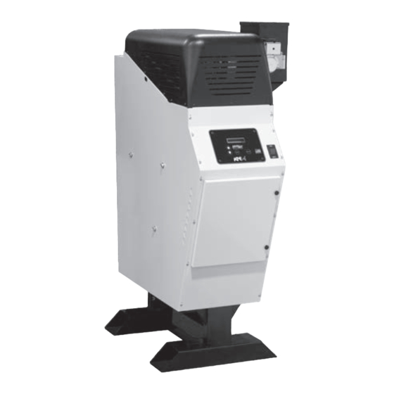
Cast Iron Condensing Boilers
Models K N-2 and K N-4
Boiler Manual
Installation and Operation
Instructions
Also read and follow:
K N Control Manual
K N Vent/Air Manual
Construction dust and particulate, particularly drywall dust, will cause contamination of
K N-2 only
12/18 Copyright 2010 Advanced Thermal Hydronics
KN-2/4-IOM2-1218
42-9450
Advertisement
Table of Contents

Related Manuals for ATH KN-2


Summary of Contents for ATH KN-2
- Page 1 KN-2/4-IOM2-1218 42-9450 Cast Iron Condensing Boilers Models K N-2 and K N-4 Boiler Manual Installation and Operation Instructions Also read and follow: K N Control Manual K N Vent/Air Manual K N-2 only This manual is intended only for use by a qualified heating installer/technician. Read and follow this manual, all supplements and related instructional information provided with the boiler.
- Page 2 Page 2 KN INSTALLATION AND OPERATION INSTRUCTIONS The K N condensing cast iron boiler Operation Overview The K N is a cast iron boiler designed and constructed to allow full condensing operation. The illustration at left shows how the boiler is heated with a down-fired premix gas burner mounted above the heat exchanger.
- Page 3 KN INSTALLATION AND OPERATION INSTRUCTIONS Page 3 The K N condensing cast iron boiler Components Gas valve Pressure/temperature gauge Jacket Cast iron section assembly K N-2 Inlet air filter access panel Blower K N HeatNet® control with keypad and display Venturi assembly Pressure switches (blocked flue and blocked air inlet)
-
Page 4: Table Of Contents
Page 4 KN INSTALLATION AND OPERATION INSTRUCTIONS Contents Read before beginning the installation ..5 Hazard icons Boiler ratings and specifications ..6 You will find the following icons Installation site preparation . -
Page 5: Read Before Beginning The Installation
• When antifreeze is used in the system, install Boiler water an approved pressure back-flow preventer. Per DOE mandate, the KN-2 operator • • You must thoroughly flush the system, with the boiler isolated from the system, to remove control incorporates an automatic means sediment. -
Page 6: Boiler Ratings And Specifications
Page 6 KN INSTALLATION AND OPERATION INSTRUCTIONS Boiler ratings and specifications K N-2 K N-4 Boiler model Units Notes AFUE (DOE seasonal efficiency) Btuh 199,999 399,999 CSA Input (Max) 116.8 Btuh 40,000 80,000 CSA Input (Min) 11.7 23.4 PSIG Maximum allowable working pressure Water supply and return connections Inches, NPT 1¼... -
Page 7: Installation Site Preparation
KN INSTALLATION AND OPERATION INSTRUCTIONS Page 7 Installation site preparation Boiler location requirements • Buildings will require the installation of a fresh air duct or other means of providing make-up air if the intake air option isn’t used. Any building utilizing other gas burning Do not install the boiler unless the location appliances, a fireplace, wood stove or any type of exhaust meets all of the requirements in this box. - Page 8 Page 8 KN INSTALLATION AND OPERATION INSTRUCTIONS Installation site preparation (continued) Clearance requirements Clearance to combustibles references Figure 1 Clearances to combustible surfaces All installations must provide the minimum clearances to combustible materials and surfaces given in Table 1. Failure to comply could result in a fire hazard, causing severe personal injury, death or substantial property damage.
- Page 9 KN INSTALLATION AND OPERATION INSTRUCTIONS Page 9 Installation site preparation (continued) Air opening options for combustion air Figure 3 Combustion air requirements drawn from boiler room Air ducted to boiler air intake If other appliances are located in the same room as the boiler, increase the size of air openings If air is ducted from outside to the boiler air intake, follow instructions in the to provide the free area required for the other...
-
Page 10: Prepare The Boiler
Page 10 KN INSTALLATION AND OPERATION INSTRUCTIONS Prepare the boiler Piping guidelines: Remove the boiler from the crate • All installations must be installed by a qualified technician Cold weather handling — The boiler jacket in accordance with the latest revision of the ANSI/ASME includes plastic parts. -
Page 11: Water Piping
KN INSTALLATION AND OPERATION INSTRUCTIONS Page 11 Water piping Boiler piping connections The K N boiler requires a continuous minimum water flow for proper operation. The circulator for the boiler must be sized to overcome the The boiler supply and return connections are shown in Figure 4. head loss of the boiler and the heating system in order to achieve the Both connections are 1-1/4 inch NPT. - Page 12 Page 12 KN INSTALLATION AND OPERATION INSTRUCTIONS Water piping (continued) Expansion tank and air separation Diaphragm or bladder-type expansion tank Figure 6 suggested piping The system must include an expansion tank to control thermal expansion. Install the tank as close as possible to the boiler, and locate on the suction side of the system circulator.
- Page 13 KN INSTALLATION AND OPERATION INSTRUCTIONS Page 13 Water piping (continued) DHW operation, when required Zoning with zone valves The piping shown throughout this manual allows for domestic water Flow balancing and control heating without flow through the heating loop(s). This is important for summertime operation of DHW tanks.
- Page 14 Page 14 KN INSTALLATION AND OPERATION INSTRUCTIONS Water piping (continued) DHW operation, when required Zoning with circulators The piping shown throughout this manual allows for domestic water Sizing and flow control heating without flow through the heating loop(s). This is important for summertime operation of DHW tanks.
- Page 15 KN INSTALLATION AND OPERATION INSTRUCTIONS Page 15 Water piping (continued) DHW operation, when required Multiple boilers, primary/secondary The piping shown throughout this manual allows for domestic water Sizing and flow control heating without flow through the heating loop(s). This is important for summertime operation of DHW tanks.
- Page 16 Page 16 KN INSTALLATION AND OPERATION INSTRUCTIONS Water piping (continued) DHW operation, when required Multiple boilers, parallel flow When heating system boilers are piped in parallel as in Figure 12, connect Sizing and flow control the DHW tank as a zone off of the main header or install boilers dedicated to the DHW application.
- Page 17 KN INSTALLATION AND OPERATION INSTRUCTIONS Page 17 Water piping (continued) Chilled water systems The boiler loop can be any of the designs in this manual, or per standard engineering practices. Use the balancing valve to adjust the boiler loop flow. General Expansion tank/air control Provide the piping components shown in Figure 13 when...
-
Page 18: Gas Piping
Page 18 KN INSTALLATION AND OPERATION INSTRUCTIONS Gas piping Check the gas type Item 3 — For all gas supply piping, use only clean, burr-free black iron pipe, supported independently from the boiler gas connection. The K N comes from the factory ready to be piped to the gas supply. - Page 19 KN INSTALLATION AND OPERATION INSTRUCTIONS Page 19 Gas piping (continued) Gas piping joints Gas flow capacity for black iron pipe Table 3 Always use a pipe sealant that is suitable for use Iron Pipe length, equivalent feet (length plus allowance for fittings) pipe with LP gas.
-
Page 20: Wiring A Single Boiler
Page 20 KN INSTALLATION AND OPERATION INSTRUCTIONS Wiring a single boiler Electrical connection board (see item 10, Figure 15 page 3 for location — Also see the wiring Electrical shock hazard — summary illustrations on the next pages) Disconnect all electrical power sources to the boiler before making any electrical connections. - Page 21 Wiring the boiler circulator using a circulator Figure 17 relay (required for motors over 1/4 hp) Wiring the boiler circulator using a relay or Figure 18 starter (required for motors over 1/4 hp) (KN-2 only)
- Page 22 Page 22 KN INSTALLATION AND OPERATION INSTRUCTIONS Wiring single boiler (continued) Sensor wiring Indoor Air Reset wiring to IAR terminals with Figure 20 4-wire zone valves and no zone controller No sensor wiring is necessary unless (see Figure 21a for terminal block 6 location). •...
- Page 23 KN INSTALLATION AND OPERATION INSTRUCTIONS Page 23 Wiring and control setup (continued) wiring summary (see Boiler manual and Control manual text for additional information) Figure 21a Also see page 20 Wire Harness 70-2043 Factory Wiring — Do Not Change J9 Control Inputs 120V 50VA 24VAC...
- Page 24 Page 24 KN INSTALLATION AND OPERATION INSTRUCTIONS Wiring and control setup (continued) wiring summary (see Figure 21 for locations) (see Boiler manual and Control manual text for additional information) Figure 21b Also see page 21 Also see page 22 (KN-2 only)
-
Page 25: Control Setup
KN INSTALLATION AND OPERATION INSTRUCTIONS Page 25 Control setup Before control setup HeatNet display during Standby (no call Figure 22 for heat) — pressing the DOWN key on the Before beginning the HeatNet control setup, remove the wires keypad changes the display as shown connected to the HEAT DEMAND and DHW DEMAND terminals on the electrical connection board (see Figure 21). - Page 26 Page 26 KN INSTALLATION AND OPERATION INSTRUCTIONS Control setup (continued) Recommended settings 1. The following recommendations should cover most single-boiler applications. 2. The settings covered in this manual are SETPOINTS, INDOOR AIR, OUT- DOOR AIR and SYSTEM CLOCK. 3. With the cursor on DHW SETPT, press the SELECT key to change the value, using the same procedure as with the 3.
- Page 27 KN INSTALLATION AND OPERATION INSTRUCTIONS Page 27 Control setup (continued) 2. The default setting is ON. 3. To change the setting, press SELECT and use the arrow keys to change from ON to OFF. 4. Press SELECT, then BACK. 5. The factory default setting is ON, or IAR enabled. If the boiler is wired for IAR, 5.
-
Page 28: Vent Piping (And Air Piping When Used)
Page 28 KN INSTALLATION AND OPERATION INSTRUCTIONS Vent piping (and air piping when used) All K N boilers must be vented using only the materials listed in the K N Vent/Air manual. The vent installation must meet requirements for direct vent (when air is ducted to the boiler air intake) or ANSI Category IV venting (when air is taken from the boiler room). -
Page 29: Condensate Drain Line
Figure 23. Securing/protecting the condensate line Figure 23 Condensate drain line connections (KN-2 shown — J-trap config- uration is the same for KN-4, but mounted directly to a clamping — Secure the condensate line to the floor... -
Page 30: Fill And Test The System
Page 30 KN INSTALLATION AND OPERATION INSTRUCTIONS Fill and test the system • After flushing the system thoroughly, use trisodium phosphate or other chemical sold for cleaning hydronic systems to remove sediment and sludge. Failure to adhere to the following could result in boiler section failure, resulting in potential for severe personal injury, death or substantial property Use caution when working with chemicals,... - Page 31 KN INSTALLATION AND OPERATION INSTRUCTIONS Page 31 Fill and test the system (continued) ❑ Antifreeze ❑ System pressure • Once the system is cleaned, filled, purged and treated as • Antifreeze for hydronic systems contains propylene glycol and an inhibitor. required, set the make-up water pressure reducing valve Without the inhibitor the glycol is actually corrosive.
-
Page 32: Starting The Boiler
Page 32 KN INSTALLATION AND OPERATION INSTRUCTIONS Starting the boiler Should overheating occur or Failure to adhere to the following could result in severe personal injury, death or substantial property damage. gas supply fail to shut off: Do not interrupt water flow to the boiler. Accessibility Instead, shut off gas supply to the boiler with the manual valve in the gas supply... - Page 33 KN INSTALLATION AND OPERATION INSTRUCTIONS Page 33 Starting the boiler (continued) ❑ Prepare the condensate system • Measure the air piping length and note the number of fittings. Make sure the air piping complies with the • Verify the condensate line is connected to the boiler, cor- K N Vent/air manual.
- Page 34 Page 34 KN INSTALLATION AND OPERATION INSTRUCTIONS Starting the boiler (continued) To reset the HeatNet control from lockout: Turn the boiler on/off switch OFF, then back ON. Figure 24a HeatNet control display during operation Figure 24b Boiler sequence of operation, fault states and HeatNet control display information Normal condition Blower status Time...
- Page 35 KN INSTALLATION AND OPERATION INSTRUCTIONS Page 35 Starting the boiler (continued) Operating instructions (for starting boiler only — follow manual instructions to check boiler operation and adjust as needed) Figure 25 FOR Y OUR SAFETY READ BEFORE OPERA TING If yo u d o not f ollow these instruc tions e xac tly , a r e o r e xplosion ma y r esult, causing WARNIN G proper ty damage , personal injur y o r loss of lif e.
- Page 36 Page 36 KN INSTALLATION AND OPERATION INSTRUCTIONS Starting the boiler (continued) En francaise . . . Illustration 26...
- Page 37 KN INSTALLATION AND OPERATION INSTRUCTIONS Page 37 Starting the boiler (continued) Turn the boiler OFF Flue gas sampling hole Figure 27 1. Turn the boiler on/off switch and allow the boiler to cycle off. 2. CLOSE the manual gas valve. 3.
- Page 38 Page 38 KN INSTALLATION AND OPERATION INSTRUCTIONS Starting the boiler (continued) Adjust gas valve throttle setting Throttle adjustment and flame window Figure 29 Allow combustion to stabilize • Allow the boiler to operate 15 minutes, or as needed to obtain a steady reading on the analyzer.
- Page 39 KN INSTALLATION AND OPERATION INSTRUCTIONS Page 39 Starting the boiler (continued) When is low fire adjustment required? Removing boiler jacket top Figure 30 Adjust the gas valve low-fire setting if the flame is unacceptable, ONLY the CO2, O2 or CO are out of acceptable range or you are changing fuels.
- Page 40 Page 40 KN INSTALLATION AND OPERATION INSTRUCTIONS Starting the boiler (continued) Measure flame current Throttle adjustment and flame window Figure 32 Electrical shock hazard — The electrical box contains line-voltage wiring and contacts. Use caution when working in the electrical box to avoid contact with line-voltage elements.
-
Page 41: Annual Start-Up
KN INSTALLATION AND OPERATION INSTRUCTIONS Page 41 Annual start-up The boiler and system must be inspected, started obstructed heat exchanger could result in severe and serviced at least annually by a qualified service personal injury, death or substantial property technician. Follow all procedures specified in damage. -
Page 42: Maintenance
Page 42 KN INSTALLATION AND OPERATION INSTRUCTIONS Maintenance Read before proceeding Handling ceramic fiber and fiberglass materials Failure to adhere to the following could result in severe personal injury, death or substantial property The K N boiler contains some ceramic damage. - Page 43 KN INSTALLATION AND OPERATION INSTRUCTIONS Page 43 Maintenance (continued) Cleaning the air filter Accessing the air filter Figure 33 1. Turn the boiler on/off switch 2. Remove the three thumb screws that secure the filter access plate (see Figure 33). 3.
- Page 44 Page 44 KN INSTALLATION AND OPERATION INSTRUCTIONS Maintenance (continued) Accessing the burner Preparing to remove upper section cover Figure 35 If the filter enclosure and blower inlet show signs of drywall dust, construction debris or other deposits, you may need to inspect the burner.
- Page 45 KN INSTALLATION AND OPERATION INSTRUCTIONS Page 45 Maintenance (continued) Notes...
-
Page 46: Replacement Parts
Page 46 KN INSTALLATION AND OPERATION INSTRUCTIONS K N-2 Replacement parts ITEM PART No. DESCRIPTION ITEM PART No. DESCRIPTION T&P Gauge 3" Flue Adapter 20-1022 56-3346 Jacket Panel Assembly 50V Transformer 70-1552 26-3211 Illuminated Rocker Switch Breakout Board w/Wire Connectors 58-1555 02-4288 Front Section... - Page 47 KN INSTALLATION AND OPERATION INSTRUCTIONS Page 47 K N-2 Replacement parts (continued)
- Page 48 Page 48 KN INSTALLATION AND OPERATION INSTRUCTIONS K N-4 Replacement parts...
- Page 49 KN INSTALLATION AND OPERATION INSTRUCTIONS Page 49 K N-4 Replacement parts (continued)
- Page 50 Page 50 KN INSTALLATION AND OPERATION INSTRUCTIONS K N-4 Replacement parts (continued) ITEM PART No. DESCRIPTION ITEM PART No. DESCRIPTION Upper Cover Burner (Only) 60-5646 70-1209 Jacket Assembly Blower 70-1554 58-1837 Display Mount Plate Wire Harness (Blower to Inline) 03-1809 40-00268 Control Overlay Blower to Swirlplate Gasket...
-
Page 51: Appendix A - Suggested Wiring
KN INSTALLATION AND OPERATION INSTRUCTIONS Page 51 Appendix A — suggested wiring IAR (Indoor Air Reset) wiring, when used Indoor Air Reset wiring to IAR terminals with Figure A1 3-wire zone valves and no zone controller Wiring for 3-wire zone valves without a zone (see Figure 21a for terminal block 6 location) controller •... - Page 52 Page 52 KN INSTALLATION AND OPERATION INSTRUCTIONS Appendix A — suggested wiring (continued) IAR (Indoor Air Reset) wiring, when used Indoor Air Reset wiring to IAR terminals with Figure A2 3-wire zone valves and no zone controller Wiring for circulator relays (relays must have (see Figure 21a for terminal block 6 location) 24VAC common terminals) Relays must have a 24VAC common terminal:...
- Page 53 KN INSTALLATION AND OPERATION INSTRUCTIONS Page 53 Appendix A — suggested wiring (continued) IAR (Indoor Air Reset) wiring, when used Wiring for typical zone controller • Heat Demand terminal connections — The end switch leads from the controller must connect to the Heat Demand terminals on the electrical connection board as shown in Figure A3.
- Page 54 Page 54 KN INSTALLATION AND OPERATION INSTRUCTIONS Appendix A — suggested wiring (continued) Indoor Air Reset wiring to IAR terminals, Heat Demand and DHW Demand using typical zone controller for Figure A3 either circulators or zone valves (see Figure 21a for terminal block 2 and 6 locations)
- Page 55 KN INSTALLATION AND OPERATION INSTRUCTIONS Page 55 Start-up & service history Installation and start-up (complete before leaving installation site) Start-up date Boiler model Serial number Installer/start-up company name and address: _____________________________________________________ Fuel (natural or LP) High fire CO High fire CO _____________________________________________________ _____________________________________________________ Low fire CO...
- Page 56 IN UNITED STATES: 260 NORTH ELM ST. • WESTFIELD, MA 01085 • (413) 564-5515 • FAX (413) 568-9613 IN CANADA: 7555 TRANMERE DRIVE • MISSISSAUGA, ONT. L5S 1L4 • (905) 670-5888 • FAX (905) 670-5782 www.knseries.com...
Need help?
Do you have a question about the KN-2 and is the answer not in the manual?
Questions and answers