Table of Contents
Advertisement
Quick Links
Advertisement
Table of Contents

Subscribe to Our Youtube Channel
Related Manuals for Crestron Cresnet Network

Summary of Contents for Crestron Cresnet Network
- Page 1 Cresnet® Network Design Guide Crestron Electronics, Inc.
- Page 2 Crestron disclaims any proprietary interest in the marks and names of others. Crestron is not responsible for errors in typography or photography.
-
Page 3: Table Of Contents
Contents Overview Cresnet Device Definitions Control Systems Cresnet Servers Cresnet Clients Network Architecture Maximum Network Size Network Topologies Home-Run Topology Daisy-Chain Topology Star-Network Topology Cresnet ID Assignment Client Device Distribution Cresnet Distribution Blocks Cresnet Distribution Block Multitype Cresnet Distribution Block DIN Rail Cresnet Distribution Block Cresnet Hubs Cresnet Hub... - Page 4 Wire Gauge Overview Resistance Equation Formula Example Scenarios External Power Supplies Appendix A: Troubleshoot Cresnet IDs Insufficient Power Incorrect Wire Gauge Incorrect Wiring Poor Wiring Excessive Cresnet Clients iv • Contents Design Guide — Doc. 9292A...
-
Page 5: Overview
Overview The Cresnet™ communications protocol is designed for Crestron devices that do not require the higher speeds of Ethernet. Cresnet provides a dependable and flexible wiring solution, allowing multiple devices to be wired together in parallel using various network topologies. A single Cresnet server can provide power and data to up to 25 client devices. -
Page 6: Cresnet Device Definitions
Cresnet hubs via its NET (Cresnet) port. Ethernet-to-Cresnet bridges can be added to a Crestron control system to expand the size of the Cresnet network, creating isolated Cresnet subnets that each behave as a Cresnet server with its own unique address space. -
Page 7: Network Architecture
A single Cresnet server supports up to 25 client devices with a maximum aggregate cable length of 1,500 ft (457 m). A Cresnet network can be expanded to contain up to 90 client devices using Cresnet hubs. Cresnet hubs also allow for longer cable runs. For more information, refer to Cresnet Hubs page 9). -
Page 8: Star-Network Topology
Cresnet IDs (NET IDs) are unique identifiers given to Cresnet devices on a network (similar to IP IDs) that allow for network communication between Cresnet clients and servers. NET IDs should be assigned using the Network Device Tree View tool in Crestron Toolbox™ software. For more information, refer to the Crestron Toolbox help file. - Page 9 Crestron recommends grouping NET IDs so that similar products on a Cresnet network are grouped together within a NET ID range. The following example shows how various product types could be grouped using NET IDs: NOTE: Grouping Cresnet IDs helps organizations to group Cresnet devices to align with various organizational standards.
-
Page 10: Client Device Distribution
Client Device Distribution A Cresnet network system with a single Cresnet server can provide power and data to up to 25 client devices with a maximum cumulative wiring run of 1,500 ft (457 m). Cresnet networks can be expanded via Cresnet distribution blocks and Cresnet hubs. Each device type and supported models are described in the following sections. -
Page 11: Multitype Cresnet Distribution Block
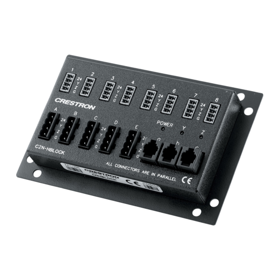
Multitype Cresnet Distribution Block C2N-HBLOCK is a parallel distribution block for the termination of multiple Cresnet cables. Three different types of connectors are provided to accommodate all types of Cresnet wiring, including standard 4-wire Cresnet cable, Cresnet High-Power (HP) cable, and RJ-11 modular cables (legacy installations only). -
Page 12: Din Rail Cresnet Distribution Block
DIN rail-mounted Cresnet distribution block designed to facilitate the termination of Cresnet wiring at a head end or distribution point. DIN rail mounting enables modular installation alongside Crestron DIN Rail lighting and automation control modules and other third-party DIN rail mountable devices. -
Page 13: Cresnet Hubs
25 client devices and 1,500 ft (457 m) of wire runs. Multiple Cresnet hubs can be added to a Cresnet network system to allow for up to 90 powered client devices. Cresnet hubs are used primarily within star-network network topologies where a single Cresnet server must power client devices across multiple rooms or locations in a facility. -
Page 14: Din Rail Cresnet Hub
Din Rail Cresnet Hub DIN-HUB is a DIN rail-mounted Cresnet hub designed for configuring large Cresnet networks. DIN rail mounting enables modular installation alongside Crestron DIN Rail lighting and automation control modules and other third-party DIN rail mountable devices. DIN-HUB DIN Rail Cresnet Hub Diagnostic LEDs indicate the presence of network activity for connected devices. -
Page 15: Ethernet-To-Cresnet Bridging
One or more bridges can be deployed on a single Cresnet client, and they can be addressed by more than one control system. The following Ethernet-to-Cresnet bridge devices are supported for expanding the size of a Cresnet network over Ethernet. Ethernet-to-Cresnet Bridge with PoE DIN-CENCN-2-POE works with any Cresnet server to maximize the reliability of a Cresnet network. -
Page 16: Ethernet-To-Cresnet Bridge For Caen Automation Enclosures
CAEN-BLOCK-CENCN-2-POE works with any Cresnet server to maximize the reliability of a Cresnet network. The bridge can be mounted at the bottom of a CAEN, CAEN-MLO, or CAENIB enclosure to provide a high-speed Ethernet interface between the enclosure and one or more outboard Cresnet servers. - Page 17 Provides a TEST button on the front panel that can be pressed to generate error codes on the LED indicators. Complete details for each error code can be viewed in a web browser or via Crestron Toolbox™ software. Design Guide — Doc. 9292A...
-
Page 18: Wiring And Connectors
Wiring and Connectors The following sections provide information about Cresnet wiring and connectors within a Cresnet network system. NOTE: To view and download drawing packages that show common Cresnet wiring scenarios, refer to Crestron Online Help article 1001565. Overview Observe the following about Cresnet wiring and connectors: All wire is calculated in American Wire Gauge (AWG) sizes... -
Page 19: Supported Cresnet Cables
Supported Cresnet Cables The following Crestron cable types are supported for Cresnet wiring runs. Cables types should be selected based on the Cresnet network installation requirements. NOTE: For more information on determining the correct wire gauge to use for Cresnet installations, refer to Calculate Power Requirements for Wire Runs (on page 21). -
Page 20: Plenum-Rated Cables
Plenum-Rated Cables CRESNET-P series cables are recommended for wiring runs within plenum spaces (such as air ducts) or applications that require plenum-rated materials. CRESNET-P series cables contain one 18 AWG pair for 24VDC and ground and one 22 AWG shielded twisted pair for control data within a plenum-rated polymer jacket. -
Page 21: Data-Only Cables
The drain wire is only used on the source or power supply end. It is trimmed and can be removed from the Cresnet network device end. When the drain wire is used, it must be added to the black (ground) wire prior to termination. -
Page 22: Best Practices
0.5 N-m). Best Practices The following best practices should be followed when wiring a Cresnet network system. CAUTION: While Cresnet devices can help to diagnose some wiring issues, certain miswirings can cause damage to the Cresnet primary device or remote network devices. Ensure all wiring best practices are followed as described below. - Page 23 NOTE: If Crestron certified wire and cable is not used and technical onsite support is required to troubleshoot an issue caused by improper wiring, a support charge may be incurred. To maintain data integrity, Cresnet cable lengths should not exceed 1,500 ft (457 m) per run.
-
Page 24: Power Requirements
Power Requirements A Cresnet network system must be designed to handle the total power that will be required by all Cresnet clients on the network. Power requirements vary based on the number of Cresnet clients in a system, the power draw for each Cresnet client, wire run lengths from a power source, and the wire gauge used. -
Page 25: Calculate Power Requirements For Wire Runs
2. Under Power Suppliers, enter the quantity of the desired Cresnet servers and power supplies within their applicable table rows. 3. Under Power Consumers, enter the quantity of the desired Cresnet clients within their applicable table rows. The Estimated Usage column on the right of the screen updates dynamically to show the current power surplus or deficit value based on the selected device quantities. -
Page 26: Example Scenarios
The R (resistance) value correlates with a wire gauge as shown in the following table. Therefore, using the equation above, the selected wire gauge must correlate with a resistance value that is less than the value derived from 40,000 / (L x PF). Resistance Value to Wire Gauge Comparison Table Resistance (R) Value Wire Gauge... -
Page 27: External Power Supplies
Cresnet server and power supply is not included in this calculation. For more information, refer to Resistance Equation Formula (on page 21). If a Cresnet network needs to be expanded beyond 1,500 ft (457 m), a Cresnet hub or Ethernet-to-Cresnet bridge is required. Design Guide — Doc. 9292A Cresnet® Network • 23... -
Page 28: Appendix A: Troubleshoot Cresnet Ids
Cresnet Power Calculator (on page 20) to determine the total power requirements for all client devices on a given leg of the Cresnet network. The total power requirements must not exceed the power supplied by Crestron servers or external power supplies on that leg. -
Page 29: Poor Wiring
No more than 25 Cresnet clients can be powered by a single Cresnet server. If more than 25 Cresnet clients are required, use a Cresnet hub or Ethernet-to-Cresnet bridge to add additional devices to the Cresnet network. Design Guide — Doc. 9292A... - Page 30 Design Guide — Doc. 9292A Crestron Electronics, Inc. 15 Volvo Drive, Rockleigh, NJ 07647 06/16/22 Tel: 888.CRESTRON Specifications subject to Fax: 201.767.7656 change without notice. www.crestron.com...
Need help?
Do you have a question about the Cresnet Network and is the answer not in the manual?
Questions and answers